
Subscribe to Our Youtube Channel
Related Manuals for Edgetech 2000-TVD


Summary of Contents for Edgetech 2000-TVD
- Page 1 2000-TVD COMBINED SONAR U S E R H A R D W A R E M A N U A L 0017424_REV_B 2/3/2018 EdgeTech 4 Little Brook Road West Wareham, MA 02576 Tel: (508) 291-0057 Fax: (508) 291-2491 www.EdgeTech.com...
- Page 2 The information, figures, and specifications in this manual are proprietary and are issued in strict confidence on condition that they not be copied, reprinted, or disclosed to a third party, either wholly or in part, without the prior, written consent of EdgeTech. Any reproduction of EdgeTech supplied software or file sharing is strictly prohibited.
-
Page 3: Attention - Read This First
ATTENTION – READ THIS FIRST! All personnel involved with the installation, operation, or maintenance of the equipment described in this manual should read and understand the warnings and cautions provided below. CAUTION! This equipment contains devices that are extremely sensitive to static electricity. -
Page 4: Hardware Variations And Compatibility
EdgeTech will make every effort to see that replacement components are interchangeable and use the same software drivers (if applicable). At times, however, direct replacements may not exist. When this happens, EdgeTech will provide the necessary drivers with the replacement part, if applicable. -
Page 5: About This Document
Purpose of this Manual The purpose of this manual is to provide the user with information on the setup and use of EdgeTech’s 2000-TVD Combined Sonar. Although this manual encompasses the latest operational features of the 2000-TV, some features may be periodically upgraded. Therefore, the information in this manual is subject to change and should be used for reference only. -
Page 6: Warranty Statement
All equipment manufactured by EdgeTech is warranted against defective components and workmanship for a period of one year after shipment. Warranty repair will be done by EdgeTech free of charge. Shipping costs are to be borne by the customer. Malfunction due to improper use is not covered in the warranty, and EdgeTech disclaims any liability for consequential damage resulting from defects in the performance of the equipment. -
Page 7: Software Service Overview
Software Updates and Enhancements EdgeTech customers can download new software releases with all modifications and enhancements from the EdgeTech ftp site. Major software issues, should they occur, will be reported directly to the customer. New software releases consist of the following: •... -
Page 8: Returned Material Authorization
RETURNED MATERIAL AUTHORIZATION Prior to returning any equipment to EdgeTech, a Returned Material Authorization (RMA) number must be obtained. The RMA will help us identify your equipment when it arrives at our receiving dock and track the equipment while it is at our facility. The material should be shipped to the address provided in the section. - Page 9 4. Small items can be shipped prepaid directly to EdgeTech by FedEx, DHL, UPS, Airborne, etc. 5. If the equipment is the property of EdgeTech (formerly EG&G Marine Instruments Division), please insure for full value. 6. Fax one invoice, packing list, and a copy of the airway bill to EdgeTech upon shipment.
-
Page 10: Customer Service
CUSTOMER SERVICE Customer service personnel at EdgeTech are always eager to hear from users of our products. Your feedback is welcome, and is a valuable source of information which we use to continually improve these products. Therefore, we encourage you to contact EdgeTech Customer Service to offer any suggestions... -
Page 11: Company Background
USBL positioning systems, and bathymetric systems—that have become standards in the industry. EdgeTech has also consistently anticipated and responded to future needs through an active research and development program. Current efforts are focused on the application of cutting-edge CHIRP and acoustic... -
Page 12: Table Of Contents
Applications ..........................1-1 Main System Components ......................1-1 1.2.1 Topside Computer ........................ 1-2 1.2.2 STARMUX III .......................... 1-2 1.2.3 2000-TVD Towfish ......................... 1-3 1.2.4 Tow Cables ..........................1-6 Optional Equipment ........................1-6 1.3.1 Magnetometer ........................1-6 1.3.2 Pressure Sensor ........................1-7 1.3.3... - Page 13 Gaussian Shaped Amplitude Spectrum Outgoing Pulse ............1-9 SPECIFICATIONS ........................2-1 Topside Computer ........................2-1 STARMUX III Digital Telemetry Link Specifications ..............2-3 2000-TVD Specifications ......................2-4 Cable Specifications ......................... 2-15 SETUP AND ACTIVATION ......................3-1 Unpacking and Inspection ......................3-1 Power Requirements ......................... 3-2 3.2.1...
- Page 14 4.1.2 STARMUX III Digital Telemetry Link ..................4-3 4.1.2.1 Selecting Negative Edge Triggering for the Optional Responder ......... 4-4 2000-TVD Towfish Description ....................4-8 MAINTENANCE ........................5-1 Periodic Maintenance ........................ 5-1 5.1.1 Inspecting and Cleaning the Towfish and Tow Cable after Use ........... 5-1 5.1.2...
- Page 15 Open Wire........................6-11 6.3.8.3 Insulation Resistance Breakdown ................6-12 6.3.8.4 Damaged Tow Cable Connector ................. 6-12 Part Numbers for Major Topside Components ............... 6-13 Part Numbers for Major 2000-TVD Towfish Components ............6-13 SYSTEM RESTORE ........................ A-1 PRINTERS ..........................B-1...
-
Page 16: List Of Figures
LIST OF FIGURES Figure 1-1: Rackmount Topside and Components ..................1-3 Figure 1-2: 2000-TVD Towfish Parts......................1-5 Figure 1-3: Kevlar Reinforced Tow Cable ....................1-6 Figure 2-1: Overall Towfish ICD Diagram ....................2-8 Figure 2-2: Fiberglass Shell of Towfish ....................... 2-9 Figure 2-3: Tow Bridle Drawing 1 ...................... - Page 17 Figure 4-6: Towfish—Electronics Chassis ....................4-11 Figure 4-7: 2000-TVD Towfish—Block Diagram ..................4-12 Figure 5-1: 2000-TVD Towfish with Top Shell Removed ................5-3 Figure 5-2: EndCap of Electronics Bottle (Connected) ................5-3 Figure 5-3: Electronics Bottle Connector End Cap ..................5-4 Figure 5-4: Remote Desktop Icon ......................
- Page 18 Table 6-3: Main Voltage Test Points on Tow Fish Power Distribution Board ..........6-9 Table 6-4: Other Voltages on SSB Board ....................6-9 Table 6-5: Major Topside Components and Part Numbers ..............6-13 Table 6-6: Major 2000-TVD Towfish Components and Part Numbers ............ 6-14 2000-TVD COMBINED SONAR 0017424_REV_B...
-
Page 19: 1.0 Overview
Marine construction surveys Main System Components The 2000-TVD system is composed of two main components: a 2000 rack mount topside and a 2000-TVD towfish. The rack mount topside includes a computer and a STARMUX III digital telemetry link installed in a 19-inch rack enclosure, along with a keyboard, a trackball, and two LCD monitors. -
Page 20: Topside Computer
The computer can also interface with a user-provided printer (see PRINTERS). The topside computer interfaces with the STARMUX III over a 10/100/1000BaseT Ethernet connection, and includes EdgeTech’s DISCOVER 2000-C Dual Frequency Side Scan Sonar software and DISCOVER Sub Bottom software preinstalled, along with the Windows 7 operating system. -
Page 21: 2000-Tvd Towfish
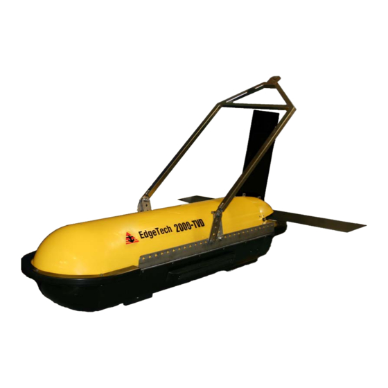
1.2.3 2000-TVD Towfish The 2000-TVD Towfish contains the side scan transducer arrays, the sub bottom transducer, and the sub- bottom hydrophone arrays, along with the electronics required to transmit and to receive the sonar signals, to receive the downlink commands from the topside computer and to provide the uplink side scan... - Page 22 (ADSL) modems in both the towfish and the processor. The 2000-TVD towfish sub-bottom sonar operates over a frequency range of 0.5–12 kHz, has a 300-meter depth rating and is designed primarily for coastal applications requiring greater bottom penetration. It is hydro-dynamically stabilized and includes the sub-bottom transducer and four sub bottom hydrophone arrays mounted under an acoustic baffle.
-
Page 23: Figure 1-2: 2000-Tvd Towfish Parts
TOW BRIDLE TAIL FINS (3) UPPER FIBERGLASS SHELL TRANSDUCERS (1 PORT, 1 STARBOARD) LOWER FIBERGLASS SHELL Figure 1-2: 2000-TVD Towfish Parts... -
Page 24: Tow Cables
Figure 1-3: Kevlar Reinforced Tow Cable Optional Equipment Optional equipment that can be installed and used with a 2000-TVD system include the following: • Magnetometer •... -
Page 25: Pressure Sensor
Full Spectrum Chirp Technology Overview EdgeTech's Full Spectrum Chirp technology has several distinct advantages over conventional side scan and sub-bottom profiling systems. These benefits include the use of separate sub-bottom acoustic projectors and receivers to enable simultaneous transmission and reception of acoustic signals, high... -
Page 26: High Signal-To-Noise Ratio
The effective spatial beam width obtained after processing a full spectrum 2–10 kHz sub bottom signal, for example is 20 degrees measured at the -3db points. 2000-TVD COMBINED SONAR 0017424_REV_B... -
Page 27: Additional Processing Gain
1.4.6 Additional Processing Gain In addition to the resolution improvement, correlation processing achieves a signal processing gain over the background noise by using a broad bandwidth transmission pulse that sweeps out over a range of frequencies instead of trying to operate with one very sharp acoustic peak pulse as is done with CW side scan and sub-bottom sonar systems. -
Page 29: 2.0 Specifications
2.0 SPECIFICATIONS The specifications for the EdgeTech 2000-TVD Combined Side Scan and Sub-Bottom Profiling System include electrical, mechanical, and environmental characteristics for the following components: • Topside computer • STARMUX III Digital Telemetry Link • 2000-TVD Towfish NOTE: All specifications are subject to change without notice. -
Page 30: Table 2-1: Topside Computer Specifications
Total shipping weight of the 2000 Topside computer and the STARMUX III mounted inside a 19-inch rack enclosure with the keyboard, the trackball and one monitor. Shipped in a sealed high impact polyurethane case. Rack enclosure weight is 41 kg (90 lb). 2000-TVD COMBINED SONAR 0017424_REV_B... -
Page 31: Starmux Iii Digital Telemetry Link Specifications
STARMUX III Digital Telemetry Link Specifications Specifications for the 2000-TVD's STARMUX III Digital Telemetry Link are as follows: SPECIFICATION VALUE 8.3 cm (3.25 in) high Size: 48.5 cm (19.0 in) wide 43.2 cm (17.0 in) deep Weight: 6.4 kg (14 lb.) -
Page 32: 2000-Tvd Specifications
2.0: SPECIFICATIONS 2000-TVD Specifications Specifications for the 2000-TVD towfish are as follows: SPECIFICATION VALUE P H Y S I C A L 226 cm (89 in.) - Length Size: 81 cm (32 in.) - Width 55 cm (22 in.) - Height Weight in air: 250 kg (550 lbs.) - Page 33 SPECIFICATION VALUE 500 m (100 kHz) 230 m (300 kHz) Operating ranges (per side): 150 m (400 kHz) 120 m (600 kHz) 4 j (100 kHz) 3 j (300 kHz) Output pulse energy: 2 j (400 kHz) 1 j (600 kHz) Up to 20 ms (100 kHz) Up to 12 ms (300 kHz) Pulse length:...
-
Page 34: Table 2-3: 2000-Tvd Towfish Specifications
<7°, 2–12 kHz Transmitters: Table 2-3: 2000-TVD Towfish Specifications Vertical resolution is the smallest distinguishable distance between the peaks of two reflections that can be displayed on the screen as separate reflectors. Sound energy is reflected to the sonar system when the transmitted pulse encounters a change in density. - Page 35 vehicle close to the sea floor reduces the acoustic footprint thereby reducing scattering (interfering reflections) from the sea floor and within the sediments. At the -3 dB points, depending on the center frequency. Specification and assembly drawings are provided on the following pages:...
-
Page 36: Figure 2-1: Overall Towfish Icd Diagram
Figure 2-1: Overall Towfish ICD Diagram... -
Page 37: Figure 2-2: Fiberglass Shell Of Towfish
Figure 2-2: Fiberglass Shell of Towfish... - Page 38 Figure 2-3: Tow Bridle Drawing 1...
- Page 39 Figure 2-4: Tow Bridle Drawing 2...
- Page 40 Figure 2-5: Towfish Assembly Drawing 2...
- Page 41 Figure 2-6: Towfish Assembly Drawing 3...
- Page 42 Figure 2-7: Towfish Assembly Drawing 4...
-
Page 43: Cable Specifications
2-15 Cable Specifications The 2000 rack mount topside can connect to the 2000-TVD towfish using a test cable (for pre-deployment testing), a 300 or 100 meter Kevlar tow cable, and a deck cable for re-terminating and connecting to a winch/armored tow cable setup 2-8). -
Page 44: Figure 2-9: 300 Meter Tow Cable Specification Drawing
Figure 2-9: 300 Meter Tow Cable Specification Drawing... -
Page 45: Figure 2-10: 100 Meter Tow Cable Specification Drawing
Figure 2-10: 100 Meter Tow Cable Specification Drawing... -
Page 46: Figure 2-11: 15M Test Cable
Figure 2-11: 15M Test Cable... -
Page 47: Figure 2-12: Deck Cable
Figure 2-12: Deck Cable... -
Page 48: Figure 2-13: Armored Tow Cable With Pmi Grip
Figure 2-13: Armored Tow Cable with PMI Grip... -
Page 49: 3.0 Setup And Activation
Also check the packing list and verify that all the items on the list are included. Again, if any damage is found, report it to the carrier and to EdgeTech. If any items are missing, immediately contact EdgeTech. Do not install or operate any equipment that appears to be damaged. -
Page 50: Power Requirements
The 2000 topside computer is auto-sensing, and therefore requires no special power configuration. Navigation Interface The 2000-TVD system accepts many standard National Marine Electronics Association (NEMA) 0183 message sentence formats from a connected global positioning system (GPS) or integrated navigation system. -
Page 51: Topside Location-Best Practices
IGURE MONITOR 1: DVI female connector. Connects to either one the two LCD monitors. For display of EdgeTech Sonar Interface and DISCOVER 2000-C Dual Frequency Side Scan screens. MONITOR 2: Two DisplayPort connectors. Connects to either one the two LCD monitors using a DisplayPort connection or with the DisplayPort to DVI adapter supplied with the system. -
Page 52: Topside Computer Controls And Indicators
SYSTEM POWER (indicator): Green indicator. Illuminated when the Topside Computer is on. RESET: Momentary push button switch. Resets the Topside Computer. HDD: Yellow indicator. Flashes when a hard drive on the Topside Computer is being accessed. 2000-TVD COMBINED SONAR 0017424_REV_B... -
Page 53: Figure 3-1: Rack Mount Topside Front Panel
Figure 3-1: Rack Mount Topside Front Panel... -
Page 55: Figure 3-2: Rack Mount Topside Back Panel
Figure 3-2: Rack Mount Topside Back Panel... -
Page 56: Starmux Iii Digital Telemetry Link Connections
The power will also be turned off if an over current or under current condition exists. To reactivate the power, turn the POWER switch off and then on again. 2000-TVD COMBINED SONAR 0017424_REV_B... -
Page 57: Tcp/Ip Address Settings
TCP/IP Address Settings The 2000 Series Combined Side Scan Sonar and Sub-Bottom Profiling System includes several Ethernet devices connected on a common local area network (LAN), and each of these devices has a factory set TCP/IP address which under normal circumstances does not require changing. However, should any of these devices be replaced, or if upgrades are later installed, it may be required that the TCP/IP addresses be reconfigured. -
Page 58: Connecting And Attaching The Tow Cable To The Towfish
Connecting and Attaching the Tow Cable to the Towfish While a Kevlar cable supplied by EdgeTech can support the weight of the towfish, to increase the life of the tow cable it is recommended to tow the tow fish using a suitable rope or cable to support the weight of the tow fish. -
Page 59: System Activation And Test
3-11 2. Verify that the tow cable is properly connected and attached to the towfish, and then connect the tow cable adapter to the tow cable and to the SEA CABLE connector of the STARMUX III Digital Telemetry Link. 3. If an external source will used to trigger the sonar, connect the trigger output of this source to the SYNC connector. -
Page 60: Figure 3-4: Discover 2000-C Dual Frequency Side Scan And Discover Sub-Bottom Windows
4. Turn on the LINE switch on the back panel of the STARMUX III Digital Telemetry Link. This switch can be left in the on position always if desired. DISCOVER 2000-C Dual Frequency Side Scan Main window DISCOVER Sub-Bottom Main window Figure 3-4: DISCOVER 2000-C Dual Frequency Side Scan and DISCOVER Sub-Bottom Windows 2000-TVD COMBINED SONAR 0017424_REV_B... -
Page 61: Performing The Pre-Deployment Checks
3-13 5. Turn on the POWER switch on the front panel. The FISH POWER indicator should illuminate; the LAN indicator should flash continuously; and the LINK indicator should flash while a reliable communications link with the towfish is being established and then illuminate continuously when the link is found. In addition, the NET indicator on the Status bar at the bottom of the Main window should indicate as follows: 3.8.2 Performing the Pre-deployment Checks... -
Page 62: Figure 3-6: Options Dialog Box, Sonar Control Tab-Discover Sub-Bottom
Click the Display tab. The Display tab shown in opens. IGURE g. On the Display tab, set the Gain to either 0 or -3 dB, and then click Norm. h. Close the Options dialog box. 2000-TVD COMBINED SONAR 0017424_REV_B... -
Page 63: Figure 3-7: Options Dialog Box, Display Tab-Discover Sub-Bottom
3-15 Figure 3-7: Options Dialog Box, Display Tab—DISCOVER Sub-Bottom CAUTION! Do not allow the sub-bottom transducer on the towfish to continuously transmit in air for an extended period as damage to the transducer could occur. From the Sonar menu, choose Sonar On. When the sonar is on, a check mark appears next to the menu item. -
Page 64: Towfish Deployment
Doing so can degrade the sonar imagery. Verify that the towfish is as level as possible when towing it. NOTE: For detailed information about the EdgeTech DISCOVER software, including how to record data, refer to the “DISCOVER 2000-C Dual Frequency Side Scan Software User’s Manual” or to the “DISCOVER Sub- Bottom Software User’s Manual.”... -
Page 65: Towfish Recovery
3-17 4. Click the Bottom Track tab. This tab is shown in 3-8. IGURE Figure 3-8: Lower Control Panel, Bottom Track Tab—DISCOVER 2000-C 5. On the Bottom Track tab make the required settings to track the bottom and note the towfish altitude in the Altitude display. - Page 66 3-18 3.0: SETUP AND ACTIVATION 8. Refer to the MAINTENANCE section for instructions on how to clean and inspect the towfish, the tow cable and the underwater connectors after use. 2000-TVD COMBINED SONAR 0017424_REV_B...
-
Page 67: 4.0 Technical Description
This section provides an overall general description of the hardware elements comprising the 2000 topside computer and the 2000-TVD towfish of the system. This information, which includes block diagrams, board descriptions, chassis photos, component callouts, and wiring diagrams, can be useful for troubleshooting purposes and installing optional equipment. -
Page 68: Figure 4-1: Topside Computer Internal Components
Figure 4-1: Topside Computer Internal Components... -
Page 69: Starmux Iii Digital Telemetry Link
4.1.2 STARMUX III Digital Telemetry Link A block diagram of the STARMUX III Digital Telemetry Link electronics is shown in 4-4. The wiring IGURE diagram is shown in 4-5, and the electronics chassis is shown in 4-4. The main hardware IGURE IGURE elements in the STARMUX III include the following components and circuit boards:... -
Page 70: Selecting Negative Edge Triggering For The Optional Responder
Selecting Negative Edge Triggering for the Optional Responder The 2000-TVD can be configured with an optional responder in the towfish. If ordered from the factory with a responder installed, the STARMUX III will have a jumper installed in the location shown in IGURE 4-2, and the customer does not need to take any further steps. -
Page 71: Figure 4-3: Starmux Iii-Internal Components
Figure 4-3: STARMUX III—Internal Components... -
Page 72: Figure 4-4: Starmux Iii-Block Diagram
COMPUTER NETWORK LAN ADSL MODEM ETHERNET ETHERNET 192.9.0.99 192.9.0.22 ADSL SEA CABLE FSIU PCB ADSL INTERFACE ADSL TOW VEHICLE (FSIC) SEA CABLE (ADSL) ADSL MODEM 192.9.0.23 TOPSIDE SONAR PROCESSOR 192.9.0.101 Figure 4-4: STARMUX III—Block Diagram... -
Page 73: Figure 4-5: Starmux Iii-Wiring Diagram
Figure 4-5: STARMUX III—Wiring Diagram... -
Page 74: 2000-Tvd Towfish Description
4.0: TECHNICAL DESCRIPTION 2000-TVD Towfish Description A wiring diagram of the 2000-TVD towfish electronics is shown in 4-7, and the electronics chassis IGURE is shown in 4-6. The electronics chassis contains all the towfish circuit boards along with the IGURE optional pressure sensor. - Page 75 T/R SWITCH: The T/R Switch board provides the transmit/receive function for the side scan transducer arrays, allowing them to be used both acoustic transmitters acoustic receivers simultaneously. Transmit signals are input from the Power Amplifier board as follows: Port low frequency transmit Port high frequency transmit Starboard high frequency transmit Starboard low frequency transmit...
- Page 76 Used to convert USB port signals to serial port signals used to ADAPTER: connect optional serial port peripheral components to the J4 bulkhead connector. Port 0 and Port 1 from the USB to serial adaptor are connected to the J4 bulkhead connector. 2000-TVD COMBINED SONAR 0017424_REV_B...
-
Page 77: Figure 4-6: Towfish-Electronics Chassis
Figure 4-6: Towfish—Electronics Chassis... -
Page 78: Figure 4-7: 2000-Tvd Towfish-Block Diagram
Figure 4-7: 2000-TVD Towfish—Block Diagram... -
Page 79: 5.0 Maintenance
5.0 MAINTENANCE The 2000 Series Combined Side Scan Sonar and Sub-Bottom Profiling System is ruggedly designed and built and therefore requires little maintenance. However, to ensure long lasting and reliable service, some periodic maintenance is recommended. This section provides some maintenance recommendations and includes instructions on how to disassemble and reassemble the 2000-CSS towfish should it be required to access and remove the electronics chassis in the electronics bottle. -
Page 80: Storage
Turn off both the Topside Computer and the STARMUX III and disconnect the tow cable before disassembling the towfish. To disassemble the tow vehicle: 1. Place the tow vehicle on a clean, dry, flat surface. 2000-TVD COMBINED SONAR 0017424_REV_B... -
Page 81: Figure 5-1: 2000-Tvd Towfish With Top Shell Removed
2. Remove the top fiberglass cover 5-1). IGURE Figure 5-1: 2000-TVD Towfish with Top Shell Removed 3. Disconnect all the cables from the connector end cap of the electronics bottle and remove the bottle from the tow vehicle 5-2). Screws for the connector end cap are shown in... -
Page 82: 5.3.1 Reassembling The Tow Vehicle
O-ring and install a new one. When installing a new O-ring, first clean the O-ring surfaces on both the housing and the end cap with the paper towel, and then apply a light coating of silicone lubricant to the 2000-TVD COMBINED SONAR 0017424_REV_B... -
Page 83: Calibrating The Compass
Calibrating the Compass The compass is calibrated at the EdgeTech manufacturing facility. Should the compass in the towfish lose its calibration for any reason in the field, it may be necessary to recalibrate it. This is accomplished by accessing the embedded Windows installation in the towfish itself via a remote desktop application on the Rack Mount Topside. -
Page 84: Figure 5-5: Remote Desktop Splash Screen
5.0: MAINTENANCE Figure 5-5: Remote Desktop Splash Screen 3. If a warning pops up as shown in 5-6, click Yes before proceeding. IGURE Figure 5-6: Remote Desktop Warning Screen 2000-TVD COMBINED SONAR 0017424_REV_B... -
Page 85: Figure 5-7: Closing Sonar.exe
4. In the remote desktop program, the embedded Windows installation in the towfish will become accessible. Shut down the Sonar.exe application running (see below): IGURE Figure 5-7: Closing Sonar.exe 5. On this desktop, click on the Tera Term command console icon 5-8). -
Page 86: Figure 5-9: Tera Term Splash Screen
5.0: MAINTENANCE Figure 5-9: Tera Term Splash Screen 2000-TVD COMBINED SONAR 0017424_REV_B... -
Page 87: Figure 5-10. Terra Term Port Set-Up
6. Establish communications with the SSAHRS and verify via a serial console. Figure 5-10. Terra Term Port Set-up Figure 5-11. Motion Sensor Serial Output... -
Page 88: Figure 5-12. Motion Sensor Calibration Result
(see 5-12). IGURE Figure 5-12. Motion Sensor Calibration Result If for some reason they are not; reset SSAHRS with the following command and then cycle power. setLevel2CompassCalibration,factory2015,0,100.0,50.0,0,0,0, 1,0,0,0,1,0,0,0,1 <CR> 2000-TVD COMBINED SONAR 0017424_REV_B... -
Page 89: Figure 5-13. Motion Sensor Serial Output
5-11 9. Restart the SSAHRS by issuing the following command, to start compass data: start <cr> Heading, Pitch, Roll, and Temperature should begin to scroll. Figure 5-13. Motion Sensor Serial Output 10. Slowly move the electronics bottle around in such a fashion as to position the compass in as many possible orientations as possible for pitch, roll and heading directions. -
Page 90: Changing The Angle Of Declination
Changing the Angle of Declination The compass' angle of declination is set to true north at the EdgeTech facility. However, to provide a more accurate target location, it is necessary to enter the known magnetic declination for the survey location into the compass as follows: 1. - Page 91 5-13 Figure 5-15 2. Verify current Declination Angle of Deviation using the following command: getDeclination <CR> Figure 5-16 3. Enter the set declination command to get help for command:...
-
Page 92: Figure 5-17: Magnetic Declination Estimated Value Screen
Here is an example of how using this website can help you to determine your angle of deviation: • Zipcode 02360 was inserted, then "Get & Add Lat/Lon" was selected: Figure 5-17: Magnetic Declination Estimated Value Screen 2000-TVD COMBINED SONAR 0017424_REV_B... -
Page 93: Figure 5-18: Angle Of Declination Calculated
5-15 • "Calculate" is then selected: Figure 5-18: Angle of Declination Calculated • The Declination Angle received was 14.47 degrees. This is the angle that will be entered into the TeraTerm command screen. 4. Enter the Declination Angle using the command: setDeclination, 14.47 <CR>... - Page 94 5-16 5.0: MAINTENANCE Verify entry of declination Angle using the command: getDeclination <CR> Figure 5-19 2000-TVD COMBINED SONAR 0017424_REV_B...
-
Page 95: 6.0 Troubleshooting
6.0 TROUBLESHOOTING Should some operational or performance problems occur with the 2000 Series Combined Side Scan Sonar and Sub-Bottom Profiling System, it may be possible to correct them using the troubleshooting guides in the following pages. For the Topside Computer and the STARMUX III Digital Telemetry Link, tabular 6-2, respectively. - Page 96 Improper settings in DISCOVER. In DISCOVER Sub-Bottom, choose Control Panel from the Sonar menu and select the Network tab from the Options dialog box. Verify that the TCP/IP Address is 127.0.0.1 and the TCP/IP Socket is 1600. 2000-TVD COMBINED SONAR 0017424_REV_B...
-
Page 97: Starmux Iii Digital Telemetry Link Troubleshooting Guide
SYMPTOM PROBABLE CAUSE CORRECTIVE ACTION Verify towfish on a different 2000 Topside computer. Verify The towfish is faulty. 2000 Topside computer with a different towfish. Table 6-1: 2000 Topside computer—Troubleshooting Guide STARMUX III Digital Telemetry Link Troubleshooting Guide SYMPTOM PROBABLE CAUSE CORRECTIVE ACTION The POWER switch in the front Verify that both POWER... -
Page 98: Towfish Troubleshooting Guide
Check all connections to the Modem disconnected internally modem are correct per the The DISCOVER survey software on digital link. wiring diagram, EdgeTech PN (if used on external topside) 0009221 reports “Cannot ping towfish” Check that under “Configuration” pull down Improper settings in DISCOVER “Network”... -
Page 99: Equipment Required
some specific areas to check which are easily identifiable and certain clues as to what to look for in making an educated guess as to the source of the problem. This is only down to the module or PCB level. The towfish is a software controlled computer system. -
Page 100: Transmission Verification
3 kHz means that self-test has failed. These tones are generated in software in the towfish and replicated on the surface when an EdgeTech topside computer is used to access the Towfish computer subsystem using the Remote Desktop application. The Self-Test PASS tones repeat until data linkup has occurred between the topside DISCOVER software, and towfish. -
Page 101: Command And Data Link
Data throughput rates on the uplink (vehicle to topside) can be critical in getting smooth data from the towfish. The data throughput rate can be checked using EdgeTech supplied utilities at each end of the link The SockBlast application is used to test network throughput between the towfish and the topside computer. -
Page 102: Towfish
Connect to towfish using REMOTE DESKTOP 192.9.0.101 login: administrator, password: admin. Sonar application should be running and there should not be any errors posted to the window. Errors reported 2000-TVD COMBINED SONAR 0017424_REV_B... -
Page 103: Power Supplies
could be: “No Sonar Device Found”, this will indicate that the CPU does not connect to the sonar processor card. “IF_DIAG” the sonar processor has detected an error and will not run. Cycle power on towfish recheck error, if the error is still present check the cables running to and from the sonar interface card. “HM_Sensors”... -
Page 104: Ddc Test Points
A TTL signal that synchronizes the topside and sub-sea units with other topside equipment. Follows the SYNC signal input on the topside unit. It is not used in all system configurations. 6.3.7.7 Other Checks Periodically check the integrity of the sea ground capacitor attached to the rear bulkhead. 2000-TVD COMBINED SONAR 0017424_REV_B... -
Page 105: Tow Cables
6-11 6.3.8 Tow Cables Historically, most system problems occur in the tow cable and their connectors. Before proceeding, verify cable continuity from the shipboard end of the cable to the towfish. The presence of a shorted or open wire in a tow cable can be determined by using a multi-meter. An open or shorted wire can be located using the techniques described in the following subsections. -
Page 106: Insulation Resistance Breakdown
If the power is not immediately removed, and the cable is not immediately retrieved and the connector flushed out with fresh water, there may be permanent damage to the connector. This will require cable re-termination. 2000-TVD COMBINED SONAR 0017424_REV_B... -
Page 107: Part Numbers For Major Topside Components
INDUCTOR, 0003081 POWER SUPPLY, 300VDC, 0006370 POWER ENTRY MODULE 0009117 Table 6-5: Major Topside Components and Part Numbers Part Numbers for Major 2000-TVD Towfish Components DESCRIPTION, PART NUMBER 100/400 300/600 COMPASS MODULE, 0008518 MEM, FLSH, 1GB, 0005181 TAIL FINS, 0017833 (or 0017847)*... -
Page 108: Table 6-6: Major 2000-Tvd Towfish Components And Part Numbers
100/400 RX XDUCER, 003028 300/600 RX XDUCER, 0008770 Table 6-6: Major 2000-TVD Towfish Components and Part Numbers 0017833 are fins used on most legacy 2000-TVD systems. For added structural integrity, 0017847 fins may be used on newer or retrofitted systems. 2000-TVD COMBINED SONAR... -
Page 109: A.0 System Restore
A.0 SYSTEM RESTORE The following section outlines the procedures for backing up and restoring the system drive. CAUTION! All data will be lost upon restoring the system to factory settings. Be sure to backup all data before preforming the procedure below. -
Page 111: B.0 Printers
Ultra 120 • Ultra 120-HD • Ultra 200 HD • EPC 1086 • EPC 1086 Old • Geoprinter 975 • TDU 850 NOTE: EdgeTech Topsides support the ETHERNET-only Printers listed above. Consult manufacturer’s operating manual printer requirements and set up.
Need help?
Do you have a question about the 2000-TVD and is the answer not in the manual?
Questions and answers