Sign In
Upload
Manuals
Brands
Edgetech Manuals
Sonar
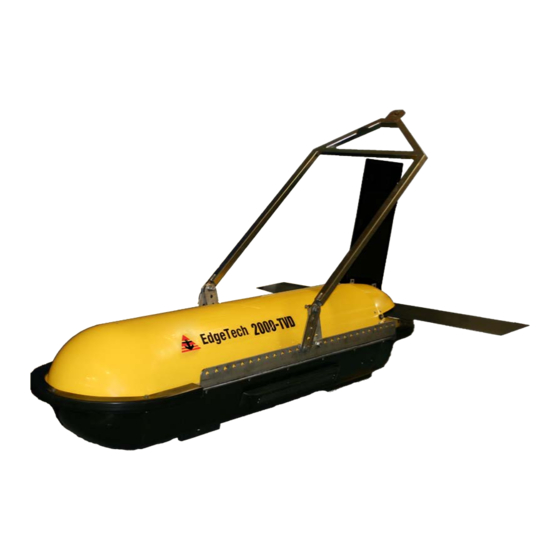
2000-TVD
Edgetech 2000-TVD Manuals
Manuals and User Guides for Edgetech 2000-TVD. We have
1
Edgetech 2000-TVD manual available for free PDF download: User Hardware Manual
Edgetech 2000-TVD User Hardware Manual (111 pages)
COMBINED SONAR
Brand:
Edgetech
| Category:
Sonar
| Size: 5 MB
Table of Contents
Attention - Read this First
3
Hardware Variations and Compatibility
4
About this Document
5
Liability
5
Warnings, Cautions, and Notes
5
Revision History
5
Warranty Statement
6
Software Service Overview
7
Software Updates and Enhancements
7
Returned Material Authorization
8
Customer Service
10
Company Background
11
Table of Contents
12
List of Figures
16
1.0 Overview
19
Applications
19
Main System Components
19
Topside Computer
20
Starmux III
20
2000-TVD Towfish
21
Figure 1-1: Rackmount Topside and Components
21
Figure 1-2: 2000-TVD Towfish Parts
23
Tow Cables
24
Optional Equipment
24
Magnetometer
24
Figure 1-3: Kevlar Reinforced Tow Cable
24
Pressure Sensor
25
Power Loss Pinger
25
Responder
25
Full Spectrum Chirp Technology Overview
25
Separate Sub-Bottom Acoustic Projectors and Receivers
25
High Signal-To-Noise Ratio
26
High Repeatability
26
High Resolution
26
Reduction of Side Lobes
26
Additional Processing Gain
27
Gaussian Shaped Amplitude Spectrum Outgoing Pulse
27
2.0 Specifications
29
Topside Computer
29
Table 2-1: Topside Computer Specifications
30
STARMUX III Digital Telemetry Link Specifications
31
Table 2-2: STARMUX III Digital Telemetry Link Specifications
31
2000-TVD Specifications
32
Table 2-3: 2000-TVD Towfish Specifications
34
Figure 2-1: Overall Towfish ICD Diagram
36
Figure 2-2: Fiberglass Shell of Towfish
37
Cable Specifications
43
Figure 2-8: Test and Deck Cable Setups
43
Figure 2-9: 300 Meter Tow Cable Specification Drawing
44
Figure 2-10: 100 Meter Tow Cable Specification Drawing
45
Figure 2-11: 15M Test Cable
46
Figure 2-12: Deck Cable
47
Figure 2-13: Armored Tow Cable with PMI Grip
48
3.0 Setup and Activation
49
Unpacking and Inspection
49
Power Requirements
50
Use of an Uninterruptable Power Supply
50
Changing to a Non-US Power Plug
50
Navigation Interface
50
Table 3-1: AC Power Cord Wiring
50
Topside Location-Best Practices
51
Topside Connections, Controls, and Indicators
51
Topside Computer Connections
51
Topside Computer Controls and Indicators
52
Figure 3-1: Rack Mount Topside Front Panel
53
Figure 3-2: Rack Mount Topside Back Panel
55
STARMUX III Digital Telemetry Link Connections
56
STARMUX III Digital Telemetry Link Controls and Indicators
56
TCP/IP Address Settings
57
Connecting the System Components
57
Table 3-2: STARMUX III Devices TCP/IP Addresses
57
Table 3-3: Towfish Ethernet Devices IP Addresses
57
Connecting and Attaching the Tow Cable to the Towfish
58
Connecting the 2000 Topside Computer
58
Figure 3-3: System Cables
58
System Activation and Test
59
Activating the System
59
Figure 3-4: DISCOVER 2000-C Dual Frequency Side Scan and DISCOVER Sub-Bottom Windows
60
Performing the Pre-Deployment Checks
61
Figure 3-5: Lower Control Panel, Transmit Tab-DISCOVER 2000-C Dual Frequency Side Scan
61
Figure 3-6: Options Dialog Box, Sonar Control Tab-DISCOVER Sub-Bottom
62
Figure 3-7: Options Dialog Box, Display Tab-DISCOVER Sub-Bottom
63
Towfish Deployment
64
Towfish Recovery
65
Figure 3-8: Lower Control Panel, Bottom Track Tab-DISCOVER 2000-C
65
4.0 Technical Description
67
2000 Topside Computer
67
Figure 4-1: Topside Computer Internal Components
68
STARMUX III Digital Telemetry Link
69
Selecting Negative Edge Triggering for the Optional Responder
70
Figure 4-3: STARMUX III-Internal Components
71
Figure 4-4: STARMUX III-Block Diagram
72
Figure 4-5: STARMUX III-Wiring Diagram
73
2000-TVD Towfish Description
74
Figure 4-6: Towfish-Electronics Chassis
77
Figure 4-7: 2000-TVD Towfish-Block Diagram
78
5.0 Maintenance
79
Periodic Maintenance
79
Inspecting and Cleaning the Towfish and Tow Cable after Use
79
Inspecting and Cleaning the Underwater Connectors
79
Storage
80
Recommended Spares
80
Restoring the Operating System to the Hard Drive
80
Disassembling and Reassembling the Towfish
80
Figure 5-1: 2000-TVD Towfish with Top Shell Removed
81
Figure 5-2: Endcap of Electronics Bottle (Connected)
81
5.3.1 Reassembling the Tow Vehicle
82
Figure 5-3: Electronics Bottle Connector End Cap
82
Calibrating the Compass
83
Figure 5-4: Remote Desktop Icon
83
Figure 5-5: Remote Desktop Splash Screen
84
Figure 5-6: Remote Desktop Warning Screen
84
Figure 5-7: Closing Sonar.exe
85
Figure 5-8: Tera Term Icon
85
Figure 5-9: Tera Term Splash Screen
86
Figure 5-10. Terra Term Port Set-Up
87
Figure 5-11. Motion Sensor Serial Output
87
Figure 5-12. Motion Sensor Calibration Result
88
Figure 5-13. Motion Sensor Serial Output
89
Changing the Angle of Declination
90
Figure 5-14: Compass Calibration Table
90
Figure 5-17: Magnetic Declination Estimated Value Screen
92
Figure 5-18: Angle of Declination Calculated
93
6.0 Troubleshooting
95
2000 Topside Computer Troubleshooting Guide
95
STARMUX III Digital Telemetry Link Troubleshooting Guide
97
Table 6-1: 2000 Topside Computer-Troubleshooting Guide
97
Towfish Troubleshooting Guide
98
Table 6-2: STARMUX III Digital Telemetry Link-Troubleshooting Guide
98
Equipment Required
99
Transmission Verification
100
Sonar Processor and Data Link
100
Topside Power Unit
100
Command and Data Link
101
Data Link
101
Figure 6-1: Sockblast Window
101
Towfish
102
Preliminary
102
No Sonar Data
102
Power Supplies
103
Test Lights
103
Table 6-3: Main Voltage Test Points on Tow Fish Power Distribution Board
103
Table 6-4: Other Voltages on SSB Board
103
DDC Test Points
104
Modem Board Test Points
104
Other Checks
104
Tow Cables
105
Shorted Wire
105
Open Wire
105
Insulation Resistance Breakdown
106
Damaged Tow Cable Connector
106
Part Numbers for Major Topside Components
107
Part Numbers for Major 2000-TVD Towfish Components
107
Figure 5-16
107
Table 6-5: Major Topside Components and Part Numbers
107
Table 6-6: Major 2000-TVD Towfish Components and Part Numbers
108
A.0 System Restore
109
B.0 Printers
111
Advertisement
Advertisement
Related Products
EdgeTech 2000-CSS
Edgetech 2000-DSS
Edgetech 2300
Edgetech 2205
Edgetech 2300B
Edgetech 2000 Series
Edgetech 2050-DSS
EDGE Tech 4125 Series
EdgeTech 4125 SIDE SCAN
Edgetech 4125I
Edgetech Categories
Marine Equipment
Sonar
Measuring Instruments
Fishing Equipment
Transceiver
More Edgetech Manuals
Login
Sign In
OR
Sign in with Facebook
Sign in with Google
Upload manual
Upload from disk
Upload from URL