Table of Contents
Advertisement
Quick Links
Advertisement
Table of Contents

Related Manuals for Nauticam NA-XT2


Summary of Contents for Nauticam NA-XT2
- Page 2 ORWARD Thank you for your purchase of a NAUTICAM housing. At NAUTICAM, we pride ourselves in the ability to recognise the requirements of professional as well as amateur underwater photographers and fulfill them through the innovative designs of our products. We strive to achieve a high level of user-friendliness by allowing stress-free installation and easy operation of all important functions of the camera.
-
Page 3: Table Of Contents
ABLE OF ONTENTS Warranty ……………………………………………………………………………………………………………. Precautions ………………………………………………………………………………………………………… Package Contents ………………………………………………………………………………………………. Specifications …………………………………………………………………………………………………….. Identification of Parts ………………………………………………………………………………………… Opening and Locking the Housing ……………………………………………………………………… Preparation of the Housing ………………………………………………………………………………… Installing the Camera …………………………………………………………………………………………. Mounting the Port ……………………………………………………………………………………………… Changing the Viewfinder ……………………………………………………………………………………. Care and Maintenance ………………………………………………………………………………………. Optional Accessories ………………………………………………………………………………………….. -
Page 4: Warranty
NAUTICAM does not hold responsibility for damage, of any nature, to any equipment used with and/or placed within our products. NAUTICAM accepts no liability for any loss of captured images or the inability to capture images even if it is due to the malfunctioning of our products. -
Page 5: Precautions
O-ring(s). • Do not use lubricants from other brands with the silicone rubber O-ring on this housing, only use the lubricant provided by NAUTICAM. • Discontinue use immediately should you notice any leakage. - Page 6 • Do not open the product in a wet or sandy environment. Protect the interior from moisture and debris in order to prevent malfunction or leakage. • Do not store the product in an environment of high humidity. • Do not leave the housing and the monitor in direct sunlight for prolonged periods. •...
-
Page 7: Package Contents
ACKAGE ONTENTS • NA-XT2 housing • Spare silicone rubber O-ring for housing • O-ring remover • CR2450 battery • Lubricant • Set of Allen keys • Instruction manual... -
Page 8: Specifications
PECIFICATIONS Housing body: Aluminium alloy Construction Surface treatment: Hard anodised Display window: Abrasion resistant polycarbonate Width: 316mm Dimensions Height: 177mm Depth: 110mm Weight Approx. 2.08kg Buoyancy Slightly negative Depth rating 100 metres Port mount Compatible Fujifilm X-T2 camera cameras... -
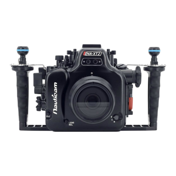
Page 9: Identification Of Parts
DENTIFICATION OF ARTS Optical fibre mount Ball mount x2 Fn2 button Focus mode selector Port alignment index Lens release button... - Page 10 Accessory coldshoe Dial lock release button Drive mode selector Sensitivity dial M16 accessory port Zoom/focus knob Port lock safety button Port lock lever *Handles are not displayed...
- Page 11 Fn1 button Dial lock release button Shutter speed dial Metering selector Exposure compensation dial On/off switch Rear command dial M14 accessory port AF-L lever Housing lock Shutter release lever safety button Front command dial Housing lock *Handles are not displayed...
- Page 12 0.66x viewfinder View mode lever AE-L button Delete button Rear command Playback button dial button Quick menu button Focus stick button Up button Left button Right button Menu/OK button Down button Display/Back button Moisture alarm window *Handles are not displayed...
- Page 13 Sacrificial zinc anode 1/4”-20UNC tripod socket x3* *The maximum length of screws that can be used with the tripod sockets is 4mm.
-
Page 14: Opening And Locking The Housing
PENING AND OCKING THE OUSING To open the housing: Press the housing lock safety Turn the housing lock anti- button. clockwise for 270°, until the lock reaches the “Open” position as shown... - Page 15 To lock the housing: Close the housing while the 2. Turn the housing lock clockwise housing is in the “Open” position. for 270°, until the lock reaches the “lock” position as shown. Confirm that the white indicator line on the safety button is visible.
-
Page 16: Preparation Of The Housing
Prepar REPARATION OF THE OUSING 1. After verifying that the main O-ring is in 4. Setting up the moisture alarm: good condition, lightly coat it with the lubricant provided. 2. Make sure the O-ring groove located in the front part of the housing is free from any foreign material;... - Page 17 Battery Installation: Press Insert the battery as shown above. Make To remove the battery, insert a small flat sure the two +ve terminals are on top of screwdriver as indicated above and gently lever it out. the battery. Then press down the battery.
- Page 18 2. Switch the alarm on. The LED 3. Test the alarm by connecting the light will flash blue once and turn two wires near the bottom of the blue for five seconds indicating housing with a damp cotton bud; the battery is normal. Then it the alarm should start giving out goes into flashing blue light a repeating “beep”...
- Page 19 Optional vacuum valve: Vacuum valve can be attached to the housing via one of the accessory port for conducting a vacuum seal test. Please refer to the manual of the vacuum valve for details of the operation. LED status identification: On start up LED indicator Status...
- Page 20 After start up LED indicator Status Standby mode. The moisture alarm is active, Flashing "Blue" light and the system is ready for vacuum indication whenever a vacuum is detected. Flashing "Red" light Moisture is detected. with beeping sound Some vacuum is detected, target vacuum level Flashing "Yellow"...
- Page 21 It is required to reset the vacuum system when the vacuum level is dropped from target level to totally lost. i.e. when opening the housing or changing port. To reset when changing port/lens: Release vacuum. Remove the port and lens from the housing and camera.
-
Page 22: Installing The Camera
NSTALLING THE AMERA To install the camera into to the housing: 2. Tilt the LCD monitor of the 1. Turn the locking lever on the tray of the housing to the “open” camera upwards, then attach position as shown. Then remove the saddle to the camera by the camera saddle from the tightening the screw to the... - Page 23 3. Lift the Drive mode selector and 4. Set the camera Drive mode to Metering selector upwards. “Panorama” and Metering to “Spot”. Then turn both selectors inwards as shown above.
- Page 24 6. Then install the camera by 8. Lock the camera into place by sliding the attached saddle turning the locking lever to the along the rail in the housing “lock” position as shown. until it cannot go in any further. 7.
- Page 25 9. Gently push the Drive mode selector and Metering selector downwards ensuring actuator correctly engages with the camera. 10. Confirm that all the controls of the housing are correctly engaged.
-
Page 26: Mounting The Port
Connect OUNTING THE Please refer to the NAUTICAM system port chart for a range of compatible ports: 1. Remove the O-ring from the port, inspect for any damage and lightly coat it with the provided lubricant before placing it back into its groove. - Page 27 Connect 4. Turn the port locking lever to 5. Lift housing cap. the release position as shown.
- Page 28 Connect 6. Align the Port mounting indices 8. Lock the port into place by of the port and the housing. turning the port locking lever to the inward position. To ensure 7. Gently push the port into the that the port is securely port opening of the housing, mounted, confirm that the...
-
Page 29: Changing The Viewfinder
Connect HANGING THE IEWFINDER In order that user can change to a preferred viewfinder easily, the 0.66x viewfinder which comes with the housing is designed so that it can be removed and re-installed by the following simple steps described below. To remove the viewfinder: Push 1. - Page 30 Connect To re-install the viewfinder: Lightly coat the O-rings on the outer periphery of the viewfinder body with lubricant. 2. Push the viewfinder from the 1. Align the viewfinder with the outside of the housing until it sleeve in the display window. cannot go in any further.
-
Page 31: Care And Maintenance
O-ring with the provided lubricant before reinstalling it in the groove. A damaged O-ring should be discarded immediately and replaced only with one that is provided by NAUTICAM. • Replace the main O-ring annually. It is recommended that you ship the housing to our... -
Page 32: Optional Accessories
Strobe Triggering A larger capacity battery provides 2x the Rapid fire manual strobe triggering is power of a single Fujifilm NP-W126s available with the Nauticam Mini Flash battery, and slides conveniently into the Trigger. underwater housing below the camera mounting plate. - Page 33 P.N. 25624 P.N. 32204 P.N. 32205 M14 Vacuum Valve II Nauticam 180˚ straight Nauticam 45˚ viewfinder for (Pushbutton Release) viewfinder for MIL housings MIL housings P.N. 25076 HDMI (D-D) Cable in 200mm Length for NA-XT2...
Need help?
Do you have a question about the NA-XT2 and is the answer not in the manual?
Questions and answers