Table of Contents
Advertisement
Quick Links
POOL & SPA HEAT PUMP
INSTALLATION/OPERATION
MANUAL
Models : AT75 • AT100 • AT115 • AT140
MODEL ____________________________________________________
SERIAL ____________________________________________________
PURCHASE DATE ___________________________________________
INSTALLING CONTRACTOR ___________________________________
Advertisement
Table of Contents

Related Manuals for aquatherm AT100


Summary of Contents for aquatherm AT100
- Page 1 POOL & SPA HEAT PUMP INSTALLATION/OPERATION MANUAL Models : AT75 • AT100 • AT115 • AT140 MODEL ____________________________________________________ SERIAL ____________________________________________________ PURCHASE DATE ___________________________________________ INSTALLING CONTRACTOR ___________________________________...
-
Page 2: Table Of Contents
Seasonal Use & Shut Down .............12 Maintenance & Operation ..........13-14 Proper Water Flow Water Chemistry Standards Irrigation and Storm Run-Off Proper Clearances Heating Tips ................15 Operational & Maintenance Recommendations ......16 Recommended Maintenance ............17 Troubleshooting ...............18 Safety Information ..............19 Aquatherm Contact Information .......Back Cover... -
Page 3: Heat Pump Options
HEAT PUMP OPTIONS The heart of your heat pump is the patented titanium heat exchanger. One of the primary causes of premature heat pump demise is the failure of the heat exchanger. Ordinary heat exchangers are made from a cupronickel alloy. This cupronickel material is susceptible to attack from the sanitizers used in pools and spas and from other related water chemistry conditions. -
Page 4: Heating Quick Start & Stop
HEATING QUICK START AND STOP 1. Verify Electrical Power is Present at Heater: A. Ensure that the unit has electrical power connected; the heater controller display should be illuminated. B. If the display is blank, be certain the electrical breaker, and heater disconnect, are switched to “ON.”... - Page 5 temperature and maintained per the setting determined previously in: “Set the Heater Controls.” In operation, whenever the actual (displayed) water temperature falls below the desired set point, after an initial time delay of 4-minutes, the unit will begin heating. THE HEATER CONTROLLER HAS AN ANTI-SHORT CYCLE TIME DELAY.
-
Page 6: Heater Controls
HEATER CONTROLS Appearance may vary by model POOL / SPA SELECTOR – Selects either pool or spa thermostat. UP ARROW – Increases temperature setting. (Maximum setting is DOWN ARROW – Decreases temperature setting. (Minimum setting is 45 HEATING INDICATOR LIGHT – Indicates unit is heating. MODE SELECTOR –... -
Page 7: Operational & Programming Codes
Service adjustments are available to authorized installation and service personnel, only. Failure to heed the following may CAUTION ! result in equipment damage and voiding of manufacturer’s warranty. owner should contact installing dealer or Aquatherm Customer Support at 239-482-0606. -
Page 8: User Lock Codes
USER LOCK CODE OPTION [ULC]: Heat pumps are shipped from the factory with the [ULC] option disabled. En- abling the [ULC] function permits the heat pump owner to restrict access to the unit’s controls. With the [ULC] function enabled, unless the correct ULC code number is entered, changes to Level-1 programming are not possible. - Page 9 2) When reset to the factory default settings the user lock code [ULC] is deacti- vated and the user lock code number [ELC] is reset to “0.” 3) In addition, all other settings are returned to the factory defaults. If an exter- nal controller is in use, contact Aquatherm Heat Pumps (888-297-3826); ask troller.
-
Page 10: Plumbing & Water Connections
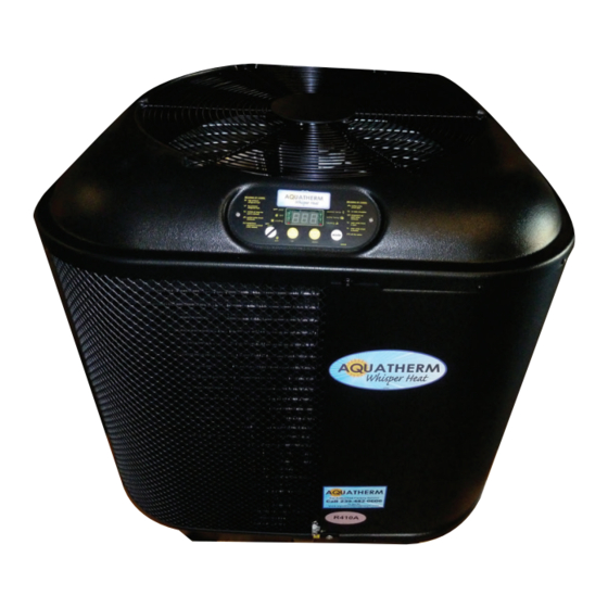
UNIT DESCRIPTION AIR DISCHARGE FAN WARNING: ROTATING BLADE KEEP HANDS & HAIR CLEAR CONTROLS WITH LED READ OUT DATA PLATE WATER IN 2” THREADED ELECTRICAL UNION INSTALLATION (INCLUDED) WATER OUT PORTS 2” THREADED UNION (INCLUDED) PLUMBING & WATER CONNECTIONS 1. BASIC PLUMBING. For a pool only or spa only, install the plumb- ing piping as shown. -
Page 11: Electrical Connections & Auto Control Instructions
4. POOL/SPA COMBINATION W/SPILL-OVER Use this diagram for a connected pool and spa, where the spa has a spill-over type waterfall into the pool. Where one pump and one heater are used for both the pool and spa. If the water pump exceeds 1.5 H.P. - Page 12 • Determine sealtight length and slip plastic POWER SUPPLY adaptor over conduit. Run conduit and proper size wire from power supply to the unit’s main contactor located on the right side of high voltage compartment. The ground wire connection is located on the base of the box to the left of the contactor.
- Page 13 B. Using the [UP] and [DOWN] arrow keys, scroll the displayed number to “50” (“50” is the default service entry pass code). C. Once the correct service code is displayed, press the [POOL/SPA] key - once again-will allow access to the service menu. make).
-
Page 14: Seasonal Use & Shut Down
AT START UP: CONTINUOUS CIRCULATION PUMP OPERATION REQUIRED ously, until the desired water temperature is attained. This may take several hours, to several days, depending upon the size of the pool or spa and weather conditions. If a time clock or similar device controls the operating times of the water circula- tion pump, temporarily override the water pump controller, allowing for 24-hour, continuous water pump operation. -
Page 15: Maintenance & Operation
(i.e.: “HP” or “HP5”) shut the heater off. valve positions. If the problem persists, please call Aquatherm at: 239-482-0606 MAINTAIN PROPER WATER CHEMISTRY • IMPORTANT! Your heat pump is engineered for exceptional durability and reliability. -
Page 16: Proper Clearances
CAUTION- POOL/SPA REFINISHING OPERATIONS again in balance and the water is clear in appearance. Failure to follow these in- structions may void heater warranty. CONTROL IRRIGATION AND STORM RUN OFF • Control Irrigation: Irrigation water spray can damage heater components. Regardless of water quality, it is important that irrigation be directed away from the heat pump. -
Page 17: Heating Tips
HEATING TIPS Heating in Cooler Weather... Late night and early morning, generally being the coolest times of the day, are least timed to operate during the warmest, daylight portions of the day. Please set water pump and heat pump controls accordingly. Pool/Spa Blankets stalling dealer to see if your heat pump was sized to be used in conjunction with a blanket. -
Page 18: Operational & Maintenance Recommendations
For service plan information, please see: Planned Maintenance Program, later in this section, or contact Aquatherm Customer Support at: 239-482-0606... -
Page 19: Recommended Maintenance
Check air temperature differential Check water temperature differential Check pool chemical levels Calibrate thermostat Annual maintenance should be performed starting one year after the installation of the heater. Call Aquatherm Customer Service at 239-482-0606 for recommendation of service company in your area. -
Page 20: Troubleshooting
(4) minutes, the “Heating” light should illuminate. If the heat pump still fails to start, and the unit is not in defrost (heat-only unit defrost display code is: “FS”), contact Aquatherm Customer Support: 239-482-0606. -
Page 21: Safety Information
Using a water test kit, or a test strip, check a sample of the water for chlorine or bromine. If the sample tests positive for sanitizer, call Aquatherm for service at: 239-482-0606. If the test is negative, the water is probably harmless condensation. - Page 22 POOL & SPA HEAT PUMPS 2213 Andrea Lane Fort Myers, FL 33912 (239) 482-0606 FAX: (239) 482-7737 (888) 297-3826 www.aquathermheatpumps.com...
Need help?
Do you have a question about the AT100 and is the answer not in the manual?
Questions and answers