aquatherm Digital Logic AT800 Installation Manual
For swimming pool & spa
Hide thumbs
Also See for Digital Logic AT800:
- Owner operational manual (12 pages) ,
- Installation manual (16 pages) ,
- Installation manual (8 pages)
Advertisement
Quick Links
SWIMMING POOL & SPA
SWIMMING POOL & SPA
HEAT PUMPS
HEAT PUMPS
INSTALLATION MANUAL
DIGITAL LOGIC™
DIGITAL LOGIC™
DIGITAL LOGIC™
DIGITAL LOGIC™
DIGITAL LOGIC™
Model AT800 AT600 & AT400
"BLACK CABINET" with
NOTICE: UNIT REQUIRES TWO,
2 INCH FEMALE ADAPTORS
FOR PLUMBING CONNECTIONS !
ELEC.
PANEL
WATER
OUT
WATER
IN
WARNING:
Specifications may change without notice. Intended for licensed factory
authorized installers only! Users should review separate owners operational manual.
WARNING: Specifications may change without notice.
V3.2-AT-D © 2001 Aquatherm Heat Pumps a division of Calorex USA L.L.C.
DIGITAL CONTROL
DIGITAL CONTROLS S S S S ONLY
DIGITAL CONTROL
DIGITAL CONTROL
DIGITAL CONTROL
SPA
POOL
MEMBER
Pool
Heat
Pump
NATIONAL
Manufacturers
POOL & SPA
Association
INSTITUTE
ONLY
ONLY
ONLY
ONLY
Advertisement

Related Manuals for aquatherm Digital Logic AT800


Summary of Contents for aquatherm Digital Logic AT800
-
Page 1: Installation Manual
Specifications may change without notice. Intended for licensed factory authorized installers only! Users should review separate owners operational manual. MEMBER Pool Heat Pump NATIONAL Manufacturers POOL & SPA Association INSTITUTE WARNING: Specifications may change without notice. V3.2-AT-D © 2001 Aquatherm Heat Pumps a division of Calorex USA L.L.C. - Page 2 Table of Contents Page 4 A. Unit Placement ..................1. Placement Requirements 2. Air Flow Clearances & Service Access 3. Gutters, Overhangs & Sprinklers Pages 5 - 7 B. Plumbing- Water Connections ..............1. Basic Plumbing 2. Chlorinator & Chemical Feeder Requirements 3.
-
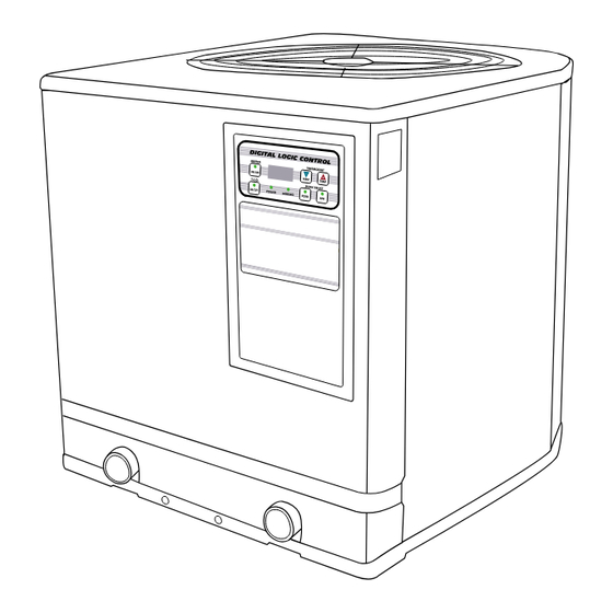
Page 3: Unit Description
Unit Description AIR DISCHARGE FAN WARNING: ROTATING BLADE KEEP HANDS & HAIR CLEAR! LED TEMPERATURE THERMOSTAT & STATUS READOUT CONTROLS POOL/SPA SERIAL NUMBER “OPTIONAL” PLATE TIME CLOCK OVERRIDE BUTTON VOLTAGE ACCESSORY PORT ELECTRICAL POOL/SPA SUPPLY WIRING SELECT ACCESS PANEL BUTTONS HIGH VOLTAGE ELECTRICAL INSTALLATION... - Page 4 Heat Pump Placement & Clearances FAN DISCHARGE AIR FLOW OUT AIR COIL AIR FLOW IN ON 3 SIDE 2” THREADED MALE PIPING CONNECTIONS WATER IN-OUT PORT INDICATOR LABEL BASE CONCRETE OR 1. To allow for proper condensation drain- PREFAB age, use a level slab to elevate the heat pump to at least the same height as the pool filter system slab or 2 to 3 inches “minimum”...
- Page 5 Plumbing & Water Connections For a simple pool only or spa only, install the plumbing piping as shown: Connections from factory are 2” threaded male pipe, requiring 2 inch female adaptors, see diagram. Use teflon tape and pipe sealer. Tighten hand tight plus 1/4 to1/2 snug tight with pliers. Water IN on the RIGHT, Water OUT on the LEFT, PLUMB AFTER the FILTER &...
- Page 6 Plumbing & Water Connections for Pool/Spa Combinations Use this diagram for a connected pool and spa, where the spa has a spill over type waterfall into the pool. Where one pump and one heater is used for either the pool or the spa. If the water pump exceeds 1.5 H.P.
- Page 7 Plumbing & Water Connections with Solar Plumbing for a system where a solar pool heater is installed. It is If the water pump exceeds 1.5 H.P. then strongly advised that an auto- install either of the optional bypasses as matic solar control device be shown on page 5.
- Page 8 Electrical Connections & Wiring The AT800, AT600 & AT400 require W A R N I N G a MINIMUM of #8 A.W.G. copper stranded wire, (or larger if needed.) You must increase the wire size DANGER FROM ELECTRICAL under low voltage, high amp draw, SHOCK &...
- Page 9 Electrical Connections & Wiring, Continued The heater has a 3/4” threaded female access port on the left side of the heater. The access port at the top is for low voltage only ! The bottom run a 3/4” conduit from the main power supply to the heater.
- Page 10 Wiring Diagram AT800, AT600 & AT400 “Digital Logic” Digital Control Models Single Phase 220 Volts Showing Optional Time Clock Override Page 10...
- Page 11 Installation for “Optional” Time Clock Override (T.C.O.) “OPTIONAL” WATER PUMP TIME CLOCK OVERRIDE OPERATION Since the heater will only heat while the water pump is running, the Time Clock Override option is available to automatically start the water pump when the nits thermostat is calling for heat. When the T.C.O.
- Page 12 Time Clock Override (T.C.O.) Installation (Cont.) Attach wires as shown, see page 13 also. Shut off main power RED- Time Clock LINE #1 disconnect for heater to T.C.O. Contactor Top Left Line & water pump ! BLACK- Time Clock LINE #2 to T.C.O.
- Page 13 Wiring Diagram for Optional Time Clock Override WARNING DANGER FROM ELECTRICAL SHOCK & ROTATING FAN ! NOTE: CAUTION: MORE THAN ONE Do not change any of the existing water DISCONNECTION MAY BE REQUIRED TO ELIMINATE ALL POWER TO THIS pump timer wiring. You will only add UNIT INCLUDING POWER TO THE wires to the existing circuit ! OPTIONAL TIME CLOCK OVERRIDE !
- Page 14 Optional Remote Key Pad Control Wiring Instructions for ”Digital Logic” Digital Control Models with Time Clock Override Option Only The AT800, AT600, & AT400 with “Digital Logic” digital control models having the External Optional Time Clock Override feature can be retrofitted with our simple, “Remote Key Pad” con- trol.
- Page 15 Optional Remote Key Pad Control Wiring Diagram for ”Digital Logic” Digital Control Models with Time Clock Override Option Only NOTE: All digital models will operate 2 Jandy motor valves without the remote key pad. #1 RED #2 BLK #3 YEL #4 GRN 240 VAC COM.
- Page 16 Interfacing “Digital Logic” Digital Control Models with: Jandy™ AquaLink RS & Compool To interface the “Digital Logic” digital control heat pump models with the Jandy™ AquaLink RS series or Compool, run a 2 wire (16 A.W.G. or larger) insulated cable from the device to the heat pump.
- Page 17 Interfacing “Digital Logic” Digital Control Models with: Aquaswitch or JI2000 If you are using a Jandy AquaSwitch or JI2000 control run a 3 wire cable from the control to the heater. Remove the 6 screws from the heaters front service access panel and open. Look for the heater’s solid state circuit board located inside the top portion of the electrical compartment mounted on the rear wall.
- Page 18 “Digital Logic” Digital Control Panel Information LED READOUT: When the unit has power the green power light will be on and the LED will display the current water temperature. THERMOSTAT BUTTONS: Pressing the + button will raise the set temperature. Pressing the - button will lower the set temperature.
- Page 19 Operational Sequence & Troubleshooting Flow Chart for “Digital Logic” Digital Control Models 220V Power Water Pump To Heater Timer Activates Green Power Light Water Pump Starts Flowing Water Pressure Water Press. SW LF Readout SW Closes Stays Open Displayed on LED No Water Flow Thermostat To Heater or...
- Page 20 Division of Calorex USA L.L.C. POOL & SPA Association INSTITUTE 2213 Andrea Lane Ft. Myers FL 33912 Specifications may change without notice. 888-297-3826 941-482-0606 © 2001 Aquatherm Heat Pumps www.aquathermheatpumps.com a Division of Calorex USA L.L.C. www.calorexusa.com Page 20...
- Page 21 How Does A Heat Pump Warm A Pool ? A swimming pool & spa pump utilizes proven refrigerant technology to capture the heat in the outside air and transfers it to the pool water. Refrigerant is used because of its ability to absorb and transfer heat energy.
- Page 22 Division of Calorex USA L.L.C. 2213 Andrea Lane Ft. Myers FL 33912 888-297-3826 941-482-0606 www.aquathermheatpumps.com www.calorexusa.com MEMBER Pool Heat Pump NATIONAL Manufacturers POOL & SPA Association INSTITUTE Specifications may change without notice. © 2001 Aquatherm Heat Pumps a division of Calorex USA L.L.C.