
Subscribe to Our Youtube Channel
Related Manuals for Hi Sharp HS-ML0840


Summary of Contents for Hi Sharp HS-ML0840
- Page 1 Thank you for purchasing our product. Please read this User’s Manual before using the product. Change without notice 8.4” CCTV RS485 LCD User’s Manual RS485 controller...
-
Page 2: Warning
WARNING: TO REDUCE THE RISK OF FIRE OR ELECTRIC SHOCK, DO NOT EXPOSE THIS PRODUCT TO RAIN OR MOISTURE. DO NOT INSERT ANY METALLIC OBJECT THROUGH VENTILATION GRILLS. CAUTION: CAUTION Explanation of Graphical Symbols The lightning flash with arrowhead symbol, within an equilateral triangle, is intended. -
Page 3: Important Information
Important Information IMPORTANT SAFEGUARDS 1. READ INSTRUCTIONS All the safety and operating instructions should be read before the unit is operated. 2. RETAIN INSTRUCTIONS The safety and operating instructions should be retained for future reference. 3. HEED WARNINGS All warnings on the unit and in the operating instructions should be adhered to. 4. -
Page 4: Safety Precautions
Safety Precautions Federal Communications Commission (FCC) Statement This Equipment has been tested and found to comply with the limits for a Class B digital device, pursuant to Part 15 of the FCC rules. These limits are designed to provide reasonable protection against harmful interference in a residential installation. -
Page 5: Table Of Contents
Table of Contents Warning……………………………………………………………………………………………………. 2 Important Information……………………………………………………………………………………. 3 Safety Precautions……………………………………………………………………………………….. 4 Table of Contents………………………………………………………………………………………… 5 Components………………………………………………………….. …………………………………. 5 Feature……………………………………………………………………………………………………. 6 Exploring Your New Monitor…………………………………………………………………………….. 7 Backside Connections…….………………………………………………………………………….…. 8 Setup your Monitor……………………………………………………………………..………………... 9 Remote controller.......................... 10 Menu Setup Image………………………………………………………………………………….…… 15 Menu Setup PIP…………………………………………………………………………………….…… 16 Menu Setup System……………………………………………………………………………………... -
Page 6: Feature
Features ■ Professional TFT LCD for surveillance in 8.4” with multiple connections ■ Compatible with SVGA (800X600) ■ Picture-In-Picture feature that allow multi-picture display ■ High brightness level and contrast ratio with super wide viewing angle ■ Built-in 3D comb filter and 3D de-interlace for display picture performance ■... -
Page 7: Exploring Your New Monitor
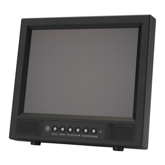
Exploring Your New Monitor You can operate your monitor by using the buttons on the front panel. The side panels provide the inputs to connect other equipment to your monitor. Front Panel Back Side... -
Page 8: Backside Connections
Backside Connections AUDIO IN (R, L) ① Stereo Audio Signal Input, this input is for VIDEO1 , VIDEO2 , S-VIDEO ② VIDEO 1 IN Composite signal Input for VIDEO 1 VIDEO 1 OUT Video looping output for VIDEO 1 VIDEO 2 IN ③... -
Page 9: Setup Your Monitor
Setup your Monitor AUTO: Auto-optimize displaying picture under PC mode. Enter: This “ Auto” Button can be either “Enter” function in OSD Menu) MENU: OSD menu ON / OFF control.(EXIT Item) ADJUST: Increase or decrease the value on OSD menu. Up: Increase value or turn ON / OFF function. -
Page 10: Remote Controller
RS485 LCD and RS485 remote controller optional... - Page 11 Before device control, please set the RS485 setup. Press RS485 set button in to RS485 menu. CAMERA ID DVR ID Protocol Pelco D Baud Rate 9600 Speed Normal Press to change control mode LCD mode User operates the function by control remote. See LCD key define DVR mode User operates the function by control remote.
- Page 12 Call desire LCD / DVR / CAM Device Menu Displays the LCD source information LCD volume setup LCD audio soundless VGA mode auto adjust Quit desire DVR OSD setup or number wrong typing Direct to select the AV1 source input Direct to select the AV2 source input Direct to select the VGA source input Direct to select the DVI source input...
- Page 13 Picture in picture of screen source exchange Picture ratio under / full / over select Channel sequence Quad screen select 9 split screen select 16 channel select Jump to playback mode Manual record Jump to time search of playback mode Jump to backup mode CAM(P/T/Z dome) PTZ dome ID select / Set;Call;Clear preset...
- Page 14 FOCUS PTZ dome’s Lens in manual focus PTZ dome’s Lens in manual focus IRIS PTZ dome’s Lens in manual Iris PTZ dome’s Lens in manual Iris ZOOM Control PTZ dome’s Lens zoom in and out PRESET Set a preset point Call a preset point Clear a preset point...
-
Page 15: Menu Setup Image
Menu Setup - IMAGE Brightness: Picture brightness adjustment Min. ~ Max.:0~100 / Default:55 Picture Contrast adjustment Contrast: Min. ~ Max.:0~100 / Default:50 Color Temp: Selects color temperature of 6500°K or 9300°K. Saturation: Picture Saturation adjustment Min. ~ Max.:0~100 / Default:50 Hue: To adjust the color tint value Min. -
Page 16: Menu Setup Pip
Menu Setup - PIP PIP Mode: This function allows the PIP mode to be selected. PIP Source: The function allows the PIP Sub source to be selected. PIP H.Position: Picture in picture window horizontal position. PIP V.Position: Picture in picture window vertical position. PIP Swap: Enable PIP sources switching. -
Page 17: Menu Setup System
Menu Setup - SYSTEM Remote Set: Remote lock, Remote controller operation denied. If there are two monitor more, user sets remote lock to on to avoid IR remote operate interference. Release lock mode, press button”0”, and then press “ID” and then “ENTER”. Monitor ID, monitor group management. If there are two monitor more, user sets monitor ID to manage group control. -
Page 18: Menu Setup Vga
Menu Setup - VGA H-position : Allows adjustment for horizontal position. V-position: Allows adjustment for vertical position. Phase: Is used to adjust best picture quality. It adjusts the sampling phase across one pixel time. When the phase is not adjusted properly, the picture will be unclear. -
Page 19: Troubleshooting
Troubleshooting Before calling a service technician, please check the following table for a possible cause of the problem and some solution. Symptom Solution Monitor will not turn on ● Makes sure the power cord is plugged in, then press POWER button. No picture, no sound ●... -
Page 20: Specifications
Specification Model 8.4” LCD Button Control Power / OSD Control / Source Display 800 x 600 @ 56/60/72/75 Resolution Active Area 170.4(H) x 127.8(V)mm Dot Pitch 0.213 (H)x 0.213(V)mm Display Ratio Brightness 250cd/m2 (*1) (Central) Contrast Ratio 600 :1 Typ. Viewing Angle Left 75°... - Page 21 RS485 jack Pin jack x 2, +/- Protocol: Pelco P / Pelco D / and customized Protocol protocol Control device Operate PTZ dome and DVR by remote controller Control ID PTZ dome 1 ~ 255 / DVR 1 ~ 255 DC power out Pin jack x 2, 5V / GND S-Video...
-
Page 22: Dimensions
Dimensions 8.4” 85-ML0840-A005G-A...
Need help?
Do you have a question about the HS-ML0840 and is the answer not in the manual?
Questions and answers