
Related Manuals for Ubiquiti UVC-G3-DOME-3


Summary of Contents for Ubiquiti UVC-G3-DOME-3
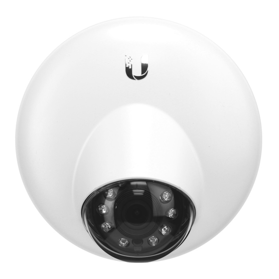
- Page 1 DOME Wide-Angle 1080p Dome IP Camera with Infrared Model: UVC-G3-DOME www.4Gon.co.uk info@4gon.co.uk Tel: (0)0330 088 0295 Fax: +44 (0)1245 808299...
-
Page 2: Package Contents
Introduction Thank you for purchasing the Ubiquiti Networks® UniFi® Video Camera G3 Dome. This Quick Start Guide is designed to guide you through installation and includes warranty terms. Package Contents G3 Dome Camera Mounting Bracket Ceiling Backing Plate Flat Head Screws... -
Page 3: Outdoor Installation Requirements
AC ground of the PoE. We recommend that you protect your networks from harmful outdoor environments and destructive ESD events with industrial-grade, shielded Ethernet cable from Ubiquiti Networks. For more details, visit www.ubnt.com/toughcable www.4Gon.co.uk info@4gon.co.uk Tel: (0)0330 088 0295 Fax: +44 (0)1245 808299... -
Page 4: Hardware Overview
Hardware Overview Bottom View Cable Gland Cable Gland For outdoor installations, ensure the rubber Cable Gland is installed for added protection. Mounting Bracket Security Slot Security Slot If you need to remove the UniFi Video Camera from the Mounting Bracket, insert a paper clip in the Security Slot to release the Lock Tab and turn the UniFi Video Camera counterclockwise. - Page 5 Ports Microphone Ethernet Reset microSD Port Button Slot The LED will light steady blue during bootup. After bootup, the LED will flash until the camera is adopted by the NVR. Upon adoption the LED will light steady blue for 10 minutes and then turn off. Ethernet The Ethernet port is a 10/100 Ethernet port used to connect the power and should be connected to the LAN and...
-
Page 6: Hardware Installation
Hardware Installation The UniFi Video Camera can be mounted on the wall or ceiling. The Ethernet cable can be fed through a hole in the wall/ceiling or can be run along the wall/ceiling. Wall Mount 1. Position the Mounting Bracket at the desired location on the wall with the Arrow pointing up. - Page 7 4. Insert the Screw Anchors into the 6 mm holes. Secure the Mounting Bracket to the wall by inserting the Screws into the anchors. 5. Remove the Cable Gland from the UniFi Video Camera. Note: For indoor installations, use of the Cable Gland is optional.
- Page 8 6. Feed the Ethernet cable through the cable opening on the Cable Gland. Note: The feed hole will stretch to accommodate the RJ45 connector, and then seal around the cable. 7. Connect the Ethernet cable to the Ethernet port. *640-00211-04* 640-00211-04 www.4Gon.co.uk info@4gon.co.uk Tel: (0)0330 088 0295 Fax: +44 (0)1245 808299...
- Page 9 8. Replace the Cable Gland. 9. If the Ethernet cable is fed through the wall, skip to step 10. If the Ethernet cable runs along the mounting surface, route the cable inside the cable channel. www.4Gon.co.uk info@4gon.co.uk Tel: (0)0330 088 0295 Fax: +44 (0)1245 808299...
- Page 10 10. Align the four tabs on the Mounting Bracket with the four slots on the bottom of the camera. Lock Tab 11. Rotate the camera clockwise until the tabs lock into place and the Lock Tab engages. www.4Gon.co.uk info@4gon.co.uk Tel: (0)0330 088 0295 Fax: +44 (0)1245 808299...
-
Page 11: Ceiling Mount
Ceiling Mount 1. Remove the ceiling tile. 2. Center the Mounting Bracket on the front side of the ceiling tile and rotate the bracket to the desired direction of the camera view. Mark the four mounting screw holes and an 18 mm hole for the Ethernet cable feed. - Page 12 4. Insert the Flat Head Screws through the Mounting Bracket, ceiling tile, and Ceiling Backing Plate. Fasten the screws using the Keps Nuts. Then feed the Ethernet cable through the tile and bracket. www.4Gon.co.uk info@4gon.co.uk Tel: (0)0330 088 0295 Fax: +44 (0)1245 808299...
- Page 13 5. Remove the Cable Gland from the UniFi Video Camera. Note: For indoor installations, use of the Cable Gland is optional. 6. Feed the Ethernet cable through the cable opening on the Cable Gland. Note: The feed hole will stretch to accommodate the RJ45 connector, and then seal around the cable.
- Page 14 7. Connect the Ethernet cable to the Ethernet port. 8. Replace the Cable Gland. www.4Gon.co.uk info@4gon.co.uk Tel: (0)0330 088 0295 Fax: +44 (0)1245 808299...
- Page 15 9. Align the four tabs on the Mounting Bracket with the four slots on the bottom of the camera. Lock Tab 10. Rotate the camera clockwise until the tabs lock into place and the Lock Tab engages. 11. Set the ceiling tile back into place. www.4Gon.co.uk info@4gon.co.uk Tel: (0)0330 088 0295 Fax: +44 (0)1245 808299...
-
Page 16: Adjusting The Camera Angle
Adjusting the Camera Angle 1. Press down on the Lens Cover and rotate it 10° counter- clockwise to disengage it. Lens Cover Note: The O-ring creates a tight seal between the Lens Cover and the camera body. Rotate the Lens Cover with your hand to break the seal. - Page 17 3. Rotate the camera body toward the desired view. 4. Tilt and rotate the camera lens assembly to set the desired view angle. www.4Gon.co.uk info@4gon.co.uk Tel: (0)0330 088 0295 Fax: +44 (0)1245 808299...
- Page 18 5. Replace the Lens Cover by aligning the two small rib tabs on the cover with the two slots on the camera body. 6. Ensure the Lens Cover is evenly seated, and then push down and rotate the cover 10° clockwise to lock it in place. www.4Gon.co.uk info@4gon.co.uk Tel: (0)0330 088 0295 Fax: +44 (0)1245 808299...
- Page 19 • Ubiquiti Networks UniFi Switch • 802.3af PoE compliant switch • Ubiquiti Networks PoE Adapter (24V, 0.5A) The single-pack of the UVC-G3-DOME includes one PoE adapter. For multi-pack units, PoE adapters or a UniFi Switch may be purchased separately.
- Page 20 Connecting to a PoE Adapter 1. Connect the Ethernet cable from the UniFi Video Camera to the POE port of the PoE Adapter. 2. Connect an Ethernet cable from your LAN to the LAN port of the PoE Adapter. 3. Connect the Power Cord to the adapter, and then plug the Power Cord into a power outlet.
- Page 21 UniFi Video Ensure that you are running UniFi Video software version 3.2 or newer. The latest version of the UniFi Video software is available at downloads.ubnt.com/unifivideo The UniFi Video auto-management feature should automatically detect your new camera(s). To manage the camera, perform the following steps: 1.
- Page 22 The camera will appear in the Managed cameras list. Note: You may need to update the firmware from the Firmware tab to complete the camera installation. UniFi Video App The UniFi Video mobile app is available for free in the App Store for iOS devices and Google Play for Android-based devices.
-
Page 23: Specifications
Specifications UVC-G3-DOME Ø 132 x 60 mm Dimensions (Ø 5.20 x 2.36") Weight 260 g (9.17 oz) Sensor 1/3" 4-Megapixel HDR Sensor Lens E.F.L 2.8mm / F2.0 Viewing Angle Before Lens Correction 100.4° (H), 59.1° (V), 117.3° (D) After Lens Correction 87.8°... -
Page 24: Safety Notices
Safety Notices Read, follow, and keep these instructions. Heed all warnings. Only use attachments/accessories specified by the manufacturer. WARNING: Hot Surface. Do not touch. WARNING: Do not use this product in location that can be submerged by water. WARNING: Avoid using this product during an electrical storm. -
Page 25: Limited Warranty
(VI) has no original Ubiquiti MAC label, or is missing any other original Ubiquiti label(s); or (VII) has not been received by Ubiquiti within 30 days of issuance of the RMA. -
Page 26: Limitation Of Liability
SUBJECT TO LIMITATIONS, INTERRUPTIONS, DELAYS, CANCELLATIONS AND OTHER PROBLEMS INHERENT IN THE USE OF COMMUNICATIONS FACILITIES. UBIQUITI NETWORKS, ITS AFFILIATES AND ITS AND THEIR THIRD PARTY PROVIDERS ARE NOT RESPONSIBLE FOR ANY INTERRUPTIONS, DELAYS, CANCELLATIONS, DELIVERY FAILURES, DATA LOSS, CONTENT CORRUPTION, PACKET LOSS, OR OTHER DAMAGE RESULTING FROM ANY OF THE FOREGOING. -
Page 27: Industry Canada
Note Some countries, states and provinces do not allow exclusions of implied warranties or conditions, so the above exclusion may not apply to you. You may have other rights that vary from country to country, state to state, or province to province. Some countries, states and provinces do not allow the exclusion or limitation of liability for incidental or consequential damages, so the above limitation may not apply to you. -
Page 28: Rohs/Weee Compliance Statement
CE Marking CE marking on this product represents the product is in compliance with all directives that are applicable to it. RoHS/WEEE Compliance Statement English European Directive 2002/96/EC requires that the equipment bearing this symbol on the product and/or its packaging must not be disposed of with unsorted municipal waste. - Page 29 Español La Directiva 2002/96/CE de la UE exige que los equipos que lleven este símbolo en el propio aparato y/o en su embalaje no deben eliminarse junto con otros residuos urbanos no seleccionados. El símbolo indica que el producto en cuestión debe separarse de los residuos domésticos convencionales con vistas a su eliminación.
-
Page 30: Declaration Of Conformity
[German] Anforderungen und den anderen relevanten Vorschriften der Richtlinie 1999/5/EG befindet. Ελληνική Δια του παρόντος, UBIQUITI NETWORKS, δηλώνει ότι αυτή η συσκευή UBIQUITI NETWORKS, είναι σε συμμόρφωση με τις [Greek] βασικές απαιτήσεις και τις λοιπές σχετικές διατάξεις της οδηγίας 1995/5/ΕΚ. -
Page 31: Online Resources
[Swedish] egenskapskrav och övriga relevanta bestämmelser som framgår av direktiv 1999/5/EG. Español Por medio de la presente UBIQUITI NETWORKS declara que este dispositivo UBIQUITI NETWORKS, cumple con los requisitos [Spanish] esenciales y cualesquiera otras disposiciones aplicables o exigibles de la Directiva 1999/5/CE. - Page 32 . u b n t . c o m ©2015-2016 Ubiquiti Networks, Inc. All rights reserved. Ubiquiti, Ubiquiti Networks, the Ubiquiti U logo, the Ubiquiti beam logo, and UniFi are trademarks or registered trademarks of Ubiquiti Networks, Inc. in the United States and in other countries.
Need help?
Do you have a question about the UVC-G3-DOME-3 and is the answer not in the manual?
Questions and answers