Table of Contents
Advertisement
Quick Links
Advertisement
Table of Contents

Subscribe to Our Youtube Channel
Related Manuals for Ubiquiti G3 Micro


Summary of Contents for Ubiquiti G3 Micro
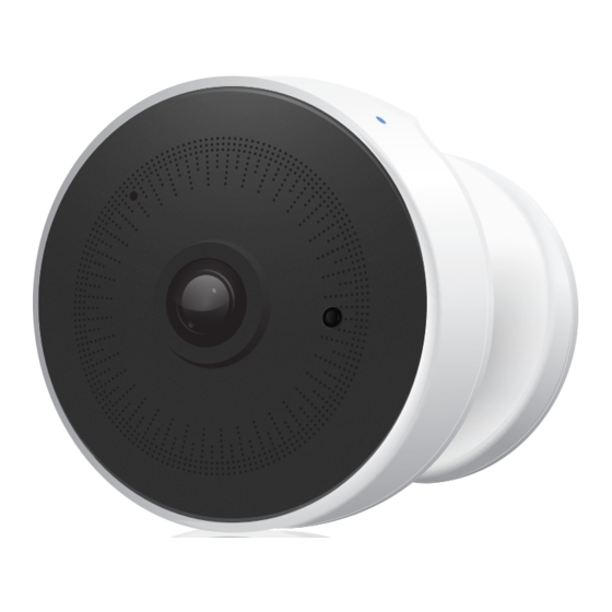
- Page 1 micro 1080p Wireless IP Security Camera with Infrared Model: UVC-G3-MICRO...
-
Page 2: Package Contents
Introduction Thank you for purchasing the Ubiquiti Networks® UniFi® Video Camera G3 Micro. This Quick Start Guide is designed to guide you through installation and also includes warranty terms. Package Contents UVC-G3-MICRO Camera Power Adapter 802.3af Instant Instant PoE Cover... -
Page 3: Before You Begin
Before You Begin The UVC G3 Micro is designed to work with the UniFi® Video (v3.8 or above) controller software. The software may be hosted on either of the following: • The Ubiquiti Networks® UniFi NVR appliance • A Linux/Windows computer... -
Page 4: Hardware Overview
Hardware Overview Reset Magnetic Base The LED will flash blue during bootup. When the camera is ready to connect to the Wi-Fi network, the LED pattern will flash two times accompanied by two beep tones. Once connected to the network, the LED will glow a breathing pattern. -
Page 5: Installation
Installation The UVC G3 Micro can be mounted in four ways: Magnetic • For temporary installation • Adhesive For fast, permanent installation • Screws For secure installation Table • For installing on a flat surface such as a table or shelf Magnetic Mount 1. -
Page 6: Adhesive Mount
3. Attach the camera and Magnetic Base directly to a metal fixture. Go to Connecting the Power. Adhesive Mount 1. If the Power Adapter cord or PoE Adapter Cord feeds through the wall, drill or cut a hole and feed the cord through it. 2. - Page 7 3. Attach the Power Adapter or Instant PoE Adapter to the Magnetic Base. 4. Attach the camera and Magnetic Base to the mount. If the power cord feeds through the Wall Mount, rotate the Magnetic Base to align the cord with the notch on the Wall Mount.
-
Page 8: Screw Mount
Screw Mount 1. If the circular connector on the Power Adapter or Instant PoE Adapter needs to connect through the wall, drill or cut a hole out and feed the power connector through it. Wall Mount Angle Mount 2. Use the Screws and Screw Anchors to fasten the Wall Mount or the Angle Mount. - Page 9 3. Attach the Power Adapter to the Magnetic Base. 4. Attach the camera and Magnetic Base to the mount. If the power cord feeds through the Wall Mount, rotate the Magnetic Base so the cord aligns with the notch on the Wall Mount.
- Page 10 Table Mount 1. Feed the circular power connector (on the Power Adapter or Instant PoE Adapter) through the hole in the Table Stand. 2. Attach the circular power connector to the Magnetic Base of the camera. 3. Attach the Magnetic Base of the camera to the Table Stand by pressing it over the two notches and sliding it down.
-
Page 11: Connecting The Power
Connecting the Power Follow the instructions for your method of powering the camera: Power Adapter or Instant PoE Adapter. Power Adapter Plug the Power Adapter into an outlet. Note: Use the included Cable Clips to hold the power cord in place. Remove the paper backing on each clip to expose the adhesive and affix to a desired location. - Page 12 2. Attach the circular power connector to the Magnetic Base of the camera. 3. Attach the Magnetic Base of the camera to the Instant PoE Mount by pressing it over the two notches and sliding it down. 4. Place the Instant PoE Cover over the Magnetic Base and onto the Instant PoE Wall Mount until it snaps into place.
- Page 13 Remove the paper backing on each clip to expose the adhesive and affix to a desired location. Setting Up the UVC G3 Micro Ensure you are running the latest version of UniFi Video, v3.8 or above on the UniFi NVR or computer-based system.
-
Page 14: Specifications
Specifications UVC-G3-Micro Dimensions Body Ø 51.38 x 41.97 mm (2.02 x 1.65") Base Ø 36.0 x 17.3 mm (1.41 x 0.68”) Weight Body 65 g (2.29 oz) Base 31 g (1.09 oz) Enclosure Characteristics White Body with Black Front Surface Mounting Options Magnetic Base, Wall Mount, or Table Mount Networking Interface... -
Page 15: Safety Notices
Safety Notices Read, follow, and keep these instructions. Heed all warnings. Only use attachments/accessories specified by the manufacturer. WARNING: Do not use this product in location that can be submerged by water. WARNING: Avoid using this product during an electrical storm. -
Page 16: Limited Warranty
Ubiquiti MAC label, or is missing any other original Ubiquiti label(s); or (VII) has not been received by Ubiquiti within 30 days of issuance of the RMA. In addition, the above warranty shall apply only if: the product has been properly installed and used at all times in accordance, and in all material respects, with the applicable Product documentation;... - Page 17 No Products will be accepted for replacement or repair without obtaining a Return Materials Authorization (RMA) number from UBIQUITI NETWORKS during the warranty period, and the Products being received at UBIQUITI NETWORKS’ facility freight prepaid in accordance with the RMA process of UBIQUITI NETWORKS.
-
Page 18: Limitation Of Liability
Limitation of Liability EXCEPT TO THE EXTENT PROHIBITED BY LOCAL LAW, IN NO EVENT WILL UBIQUITI OR ITS SUBSIDIARIES, AFFILIATES OR SUPPLIERS BE LIABLE FOR DIRECT, SPECIAL, INCIDENTAL, CONSEQUENTIAL OR OTHER DAMAGES (INCLUDING LOST PROFIT, LOST DATA, OR DOWNTIME COSTS), ARISING... -
Page 19: Industry Canada
• Reorient or relocate the receiving antenna. • Increase the separation between the equipment and receiver. • Connect the equipment into an outlet on a circuit different from that to which the receiver is connected. • Consult the dealer or an experienced radio/TV technician for help. This radio transmitter FCC ID: SWX-UVCG3M has been approved by FCC. - Page 20 RF Exposure Warning The antennas used for this transmitter must be installed to provide a separation distance of at least 20 cm from all persons and must not be located or operating in conjunction with any other antenna or transmitter. Les antennes utilisées pour ce transmetteur doivent être installé...
- Page 21 RoHS/WEEE Compliance Statement English European Directive 2012/19/EU requires that the equipment bearing this symbol on the product and/or its packaging must not be disposed of with unsorted municipal waste. The symbol indicates that this product should be disposed of separately from regular household waste streams.
- Page 22 Español La Directiva 2012/19/UE exige que los equipos que lleven este símbolo en el propio aparato y/o en su embalaje no deben eliminarse junto con otros residuos urbanos no seleccionados. El símbolo indica que el producto en cuestión debe separarse de los residuos domésticos convencionales con vistas a su eliminación.
-
Page 23: Declaration Of Conformity
Íslenska [Icelandic] Hér með lýsir UBIQUITI NETWORKS yfir því að þetta UVC-G3-MICRO tæki er í samræmi við grunnkröfur og aðrar kröfur, sem gerðar eru í tilskipun 2014/53/EU. Fullur texti ESB samræmisyfirlýsing er að finna á eftirfarandi netfangi: www.ubnt.com/compliance... -
Page 24: Online Resources
©2017 Ubiquiti Networks, Inc. All rights reserved. Ubiquiti, Ubiquiti Networks, the Ubiquiti U logo, the Ubiquiti beam logo and UniFi are trademarks or registered trademarks of Ubiquiti Networks, Inc. in the United States and in other countries. All other trademarks are the property of their respective owners.
Need help?
Do you have a question about the G3 Micro and is the answer not in the manual?
Questions and answers