Table of Contents
Advertisement
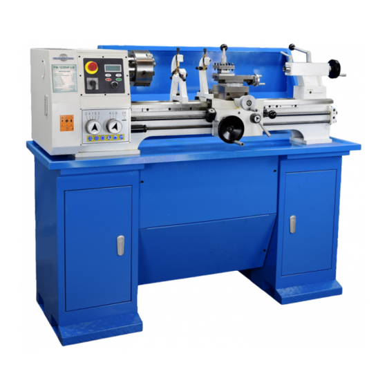
Model PM-1228VF-LB Lathe
110 Vac 2 HP heavy-duty machine
Variable spindle speed from 50 - 2000 rpm
Large 1-1/2 in. bore spindle
D1-4 camlock spindle mount
28 in. between centers, 12 in. swing over bed
Multi-speed gearbox for full-range screw cutting, TPI & mm pitch
Bidirectional power feed for saddle & cross-slide
Weight, excluding stand 490 lb
PM-1228VF-LB shown with 3-jaw chuck, steady rest
and traveling rest. Installed on optional stand.
PM-1228VF v3 2021-05
Copyright © 2021 Quality Machine Tools, LLC
1
Advertisement
Table of Contents

Related Manuals for Precision matthews PM-1127VF-LB


Summary of Contents for Precision matthews PM-1127VF-LB
- Page 1 Model PM-1228VF-LB Lathe 110 Vac 2 HP heavy-duty machine Variable spindle speed from 50 - 2000 rpm Large 1-1/2 in. bore spindle D1-4 camlock spindle mount 28 in. between centers, 12 in. swing over bed Multi-speed gearbox for full-range screw cutting, TPI & mm pitch Bidirectional power feed for saddle &...
- Page 2 Please email us if you have questions about any aspect of the manual or your machine (see our website www.precisionmatthews.com for support addresses). Your feedback is welcomed! This material was originated by Precision Matthews. No portion of the manual may be reproduced or distributed in any form without the written approval of Quality Machine Tools, LLC.
-
Page 3: Section 1 Installation
Section 1 INSTALLATION THESE ARE THE MAIN POINTS TO WATCH OUT FOR! But read the following pages for more information Check oil level in the gearbox before use • Handling the lathe is at least a two-man job. • Lifting gear – sling, hoist or forklift – must be rated for at least 1/2 ton. •... -
Page 4: Power Requirement
amount of leverage, it may be more convenient to replace the threaded stems with hex head screws (M12 x 1.75). Screw length should be 50 mm, but 45 mm (even 40 mm) will do if the floor is reasonably level. Adjust using a 19 mm or 3/4” ratcheting wrench. -
Page 5: Section 2 Features & Specifications
Section 2 FEATURES & SPECIFICATIONS MODEL PM-1228VF-LB Lathe General information The PM-1228VF-LB features a high-torque 2 HP brushless DC motor giving smoothly variable spindle speeds in two ranges, from 50 to 1000 rpm and 100 to 2000 rpm. Power requirement is 110 V, 60Hz. The lathe ships fully assembled, net weight 490 lb. - Page 6 Everyday precautions • This machine is intended for use by experienced users familiar with met- al-working hazards. • Untrained or unsupervised operators risk serious injury. • Wear ANSI-approved full-face or eye protection at all times when using the machine (everyday eyeglasses are not reliable protection against flying parti- cles).
- Page 7 PM-1228VF-LB SPECIFICATIONS Width 59 in. x Height 49 in. x Depth 28 in. Footprint (excluding handles): Width 56 in. x Depth 20 in. Bed length, excluding headstock: 42 in. Dimensions, approximate overall, incl. stand Bed width: 6-1/4 in. Spindle centerline to floor (on stand): 44 in. Weight, approximate:490 lb net, with stand 600 lb net Power requirement 110 Vac, 60 Hz, 1Ø, 20A circuit...
-
Page 8: Section 3 Using The Lathe
Section 3 USING THE LATHE The PM-1228VF-LB is a conventional engine lathe that re- quires little explanation except for details specific to this partic- ular model — speed selection, thread cutting, and the saddle/ cross-slide power feed system. The user is assumed to be familiar with general purpose metal lathes. - Page 9 tion of the stop screw is NOT to clamp the stud in place, but The speed display is unlit when the power switch is OFF (0), or instead to prevent it from being unscrewed when the chuck is if the Emergency Stop (E-Stop) button is pressed. When pow- not installed.
- Page 10 tap the backplate gently with a soft (dead blow) mallet, while holding the chuck body with the other hand. SADDLE For manual turning operations the saddle is traversed left to right along the bed by a handwheel, Figure 3-10.The saddle may be locked in place by an M8 socket head cap screw at right of the cross-slide, Figure 3-11.
- Page 11 pound to be locked at any desired angle. The cross-slide, only, can be locked in place by a socket head M6 cross-slide cap screw that clamps the gib against the mating dovetail, Fig- lock screw ure 3-14. The graduated collars on both cross-slide and compound are not locked to the leadscrews.
- Page 12 THE QUICK CHANGE TOOLPOST USING CUTTING TOOLS A popular fix for most height-setting and other tool handling In most turning operations the cutting tool is solidly mounted issues is replacement of the 4-way turret with a QCTP (Quick on the compound, and is moved relative to the workpiece by Change Tool Post).
- Page 13 TAILSTOCK SETTING UP THE POWER FEED The tailstock leadscrew has a 10 TPI thread, with 4 inch travel. The PM-1228VF gearbox is driven by a train of external gears A graduated collar on the tailstock handwheel reads 0.001” taking power from the spindle gear. It has two power-feed out- per division.
- Page 14 Reverse idler Cover safety switch Spindle pulley Figure 3-21 Shifter assembly This assembly transfers drive from the spindle gear (not shown) to the upper change gear, typi- Shifter assembly cally 30T. To reverse the gearbox input the shifter assembly is pivoted upwards, adding the second Idler assembly 46T idler (B) to the drive train.
- Page 15 SETTING UP THE POWER FEED (continued) EXTERNAL GEAR SWAPPING Key fact ... For all thread cutting, with a single exception, the middle gears are always 86T and 91T, and the lower gear is al- ways 90T. The one exception is 13 threads per inch (TPI). Non-metric applications Most users find that the machine as supplied, with 30T upper gear, meets all typical needs without alteration —...
- Page 16 Figure 3-25 Power feed enabled Move the split-nut lever to the right, but NOT as far as it will go — go to the detent position, no further. Figure 3-27 Saddle feed engaged To select saddle feed, pull the power feed lever toward you, then twist it to bring the LEFT-RIGHT arrows upper- most.
-
Page 17: Thread Cutting
REVERSING THE POWER FEED THREAD CUTTING The direction of feed shaft and leadscrew, relative to spindle Key facts ... rotation, is reversed simply by engaging an extra idler in the TPI threads external drive train. To do this, first stop the spindle, then See Figure 3-33. - Page 18 CUTTING PROCEDURE FOR TPI THREADS [NOTE: Disengagement and re-engagement of the split- This procedure assumes that a single point thread cutting tool nut is not applicable to metric threads — leave the split- will be used, and that the worm wheel on the threading dial nut engaged throughout the entire process] assembly properly engages the leadscrew, Figure 3-32.
- Page 19 UNC/UNF THREADS Sorted by TPI value For 13, 19 & 26 TPI, see the page following Metric Threads 30T upper gear 49T upper gear 60T upper gear Gearbox Gearbox Gearbox Figure 3-34 Threading dial visualization for selected U.S. threads PM-1228VF v3 2021-05 Copyright ©...
-
Page 20: Metric Thread Cutting
METRIC THREAD CUTTING METRIC THREADS Upper gear Gearbox 0.75 1.75 1.25 0.75 Metric threads sorted by pitch Figure 3-35 General setup for Metric threads Upper In this setup the lower gear is driven through the Upper Pitch Gearbox Pitch Gearbox gear translating gear pair, 86T + 91T. - Page 21 STEADY & FOLLOWER RESTS File photo Short, rigid workpieces mounted in a chuck can typically be machined without additional support. Long, slender workpiec- es need support near the cutting tool. There are two options for this: 1. A tailstock center (usually a live center), or; 2. A steady rest, Figure 3-37.
- Page 22 ALIGNING THE LATHE quill. If the centers are aligned, the blade will point squarely front to back. If not, adjust the tailstock offset by a series of very small adjustments. The most important attribute of a properly set up lathe is its If the range of quill motion permits, check the blade align- ability to “machine parallel”, to cut a cylinder of uniform diame- ment at various extensions of the quill.
-
Page 23: Section 4 Servicing The Lathe
Section 4 SERVICING THE LATHE Disconnect power before any maintenance operation! Remove all machining debris and foreign objects before lubricating ANYTHING! Use the recommended lubricants or similar. Any oil is better than no oil – but only as a stop gap. GENERAL Aside from abrasive particles and machining debris, lack of proper lubrication is the main cause of premature wear. - Page 24 LUBRICATION — OILERS Figure 4-6 Shifter assembly oilers The two Zerk fittings are intended for oil, not grease. They may be difficult to get to, in which case one alternative is to remove the fittings altogether and replace them with (say) short socket head cap screws, which can be removed to al- low oil to be squirted directly into the axles.
- Page 25 The cross-slide and compound slide on ground dovetail ways, Their function is only to hold the saddle firmly down on the Figure 4-8. In the gap between inner and outer dovetails is a bed ways, not to prevent front-to-back motion — that restraint thin gib strip, usually cast iron.
- Page 26 ADJUSTMENT — LEADSCREW SPLIT-NUT ADJUSTMENT — SPINDLE BEARINGS Locknut #281 Screw #251 Figure 4-14 Split-nut adjustment M5 socket head cap screws, 8 mm locknuts Upper and lower split nuts run in vertical dovetails in the apron, see part(s) #605 in the Apron parts diagram. The split-nut le- Figure 4-16 Pin wrench for spindle locknut ver at the front of the apron should move smoothly, but with The inside rim of the wrench may need easing with a file or grinder...
- Page 27 Figure C, this can be done with a drill press or mill if the saddle is removed Precision Matthews. The kit comes with two support plates, one for the reading head, the other for the scale. Expect to do a few hours of shop work —...
- Page 28 M4 skt heads. are doing this with the saddle in place, see the separate lathe DRO installation note from Precision Matthews.) For the installation illustrated here the saddle was removed and milled as Figure C for a flat, vertical surface.
- Page 29 were milled to size. up or down. Check again for front-to-back positioning. Fine-tune the scale position if necessary. 17. Indicate the top surface of the scale as in Figure K. Ad- just the scale up/down for an end-to-end difference of not more than 0.010″.
-
Page 30: Setting Up The Display
Figure L Height setting block Figure Q Cover installed SETTING UP THE DISPLAY The following applies only to the Precision Matthews brand lathe DRO display. Switch off the display before connecting cables! • Plug the cross-slide (X axis) cable into the upper port on Figure M Indicating the scale side the display unit. -
Page 31: Section 5 Parts
Section 5 PARTS Ref Description Part MOTOR & CONTROL BOARD Fig 1 Flat washer 8 Z2194 Screw M6 x 16 Z2195 Internal circlip 37 Z2196 Idler wheel Z2197 External circlip 12 Z2198 Bearing 6301 Z2199 Shaft Z2200 Nut M8 Z2201 Spring washer 8 Z2202 Screw M8 x 25... - Page 32 Fig 2 There may be detail differences between this representative drawing and the machine as supplied Ref Description Part Ref Description Part Ref Description Part Backsplash Z2225 Screw M4 x 8 Z2234 Round pin 8 x 16 Z2243 Screw M8 x 12 Z2226 Feed shaft Z2235...
- Page 33 HEADSTOCK Fig 3 There may be detail differences between this representative drawing and the machine as supplied PM-1228VF v3 2021-05 Copyright © 2021 Quality Machine Tools, LLC...
- Page 34 HEADSTOCK Fig 3 Ref Description Part Ref Description Part Spindle cover Z2252 Spindle gear Z2285 Screw M5 x 12 Z2253 Spindle spacer bush Z2286 Lock washer 4 Z2254 Oil seal Z2287 Flat washer 4 Z2255 Bearing 6010-2Z Z2288 Spring washer 4 Z2256 Internal circlip 80 Z2289...
- Page 35 EXTERNAL GEARS Fig 4 There may be detail differences between this representative drawing and the machine as supplied Quadrant slot * Gear size depends on thread to be cut To allow engagement of the special 56T middle gear for 13TPI thread cutting it may be necessary to trim 2 corners off nut #835, inset.
- Page 36 GEARBOX Fig 5 There may be detail differences between this representative drawing and the machine as supplied PM-1228VF v3 2021-05 Copyright © 2021 Quality Machine Tools, LLC...
- Page 37 GEARBOX Fig 5 Ref Description Part Ref Description Part Screw M5 x 12 Z2371 Gear assembly 13T/40T Z2407 Oil seal 22 x 35 x 7 Z2372 O-ring 12.5 x 1.8 Z2408 End cap Z2373 Intermediate shaft Z2409 Decal Z2374 Screw M5 x 8 Z2410 Key 4 x 4 x 16 Z2375...
- Page 38 SADDLE Fig 6 There may be detail differences between this representative drawing and the machine as supplied. One instance: gib screws 535 and lock screw 534 are shown on the opposite side of the cross-slide casting. Not shown in the above diagram Power feed gear (meshes...
- Page 39 SADDLE Fig 6 Ref Description Part Ref Description Part Screw M8 x 20 Z2443 Screw M8 x 45 Z2467 T-nut, compound base Z2444 Screw M8 x 40 Z2468 Cross slide casting Z2445 Flat washer 8 Z2469 Pin 3 x 18 Z2446 Screw M8 x 35 Z2470...
- Page 40 APRON Fig 7 There may be detail differences between this representative drawing and the machine as supplied Feedback selector shaft #619 drives #648 forward (saddle feed) or back (cross-slide) Dimensions in millimeters Ref Description Part Ref Description Part Ref Description Part Screw M5 x 35 Z2491...
- Page 41 COMPOUND Fig 8 There may be detail differences between this representative drawing and the machine as supplied Ref Description Part Ref Description Part Ref Description Part Toolpost lock handle Z2548 Knob M10 Z2558 Screw M6 x 20 Z2568 Toolpost lock nut Z2549 Support flange Z2559...
- Page 42 TAILSTOCK Fig 9 There may be detail differences between this representative drawing and the machine as supplied Ref Description Part Ref Description Part Ref Description Part Quill clamp handle Z2577 Handwheel Z2587 Tailstock body Z2597 Tailstock clamp handle Z2578 Leaf spring Z2588 Screw M8 x 16 Z2598...
Need help?
Do you have a question about the PM-1127VF-LB and is the answer not in the manual?
Questions and answers