Advertisement
Quick Links
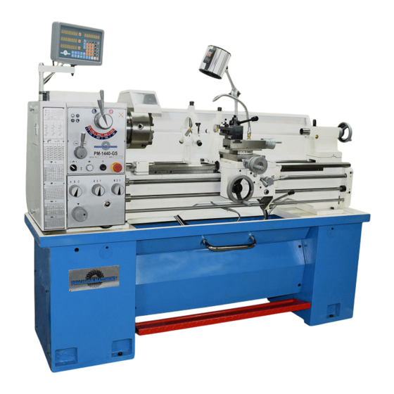
Model PM-1440GS Lathe
High precision 3 HP gap-bed machine, with 2-axis DRO
2 inch spindle bore, with stock-centering spider
D1-5 camlock spindle mount
40 in. between centers, 14 in. swing over bed, 19-3/4 in. over gap
8 spindle speeds from 60 to 1800 rpm
Multi-speed gearbox for full-range screw cutting, TPI & mm pitch
Bidirectional power feed for saddle & cross-slide
Weight, including cast iron stand & coolant system 1800 lb
PM-1440GS standard configuration Includes 2-axis DRO, 3-jaw (reversible) & 4-jaw chucks, faceplate,
coolant system, footbrake, worklight, steadies, wedge-type QC toolpost, assembled on cast iron stand
1
PM-1440GS v3 2020-10
Copyright © 2020 Quality Machine Tools, LLC
Advertisement

Subscribe to Our Youtube Channel
Related Manuals for Precision matthews PM-1440GS


Summary of Contents for Precision matthews PM-1440GS
- Page 1 Bidirectional power feed for saddle & cross-slide Weight, including cast iron stand & coolant system 1800 lb PM-1440GS standard configuration Includes 2-axis DRO, 3-jaw (reversible) & 4-jaw chucks, faceplate, coolant system, footbrake, worklight, steadies, wedge-type QC toolpost, assembled on cast iron stand PM-1440GS v3 2020-10 Copyright ©...
- Page 2 Rotate it, should pop out. This manual contains essential safety advice on the proper setup, operation, maintenance, and service of the PM-1440GS lathe. Failure to read, understand and follow the manual may result in property damage or serious personal injury.
- Page 3 Install six 500 lb-rated leveling mounts in the mounting holes of the two stand cabinets, 4 for the left hand cabinet, 2 for The PM-1440GS is shipped fully assembled in a single pack- the right. Alternatively, level the lathe using metal shims under ing case.
- Page 4 POWER CONNECTION In other words, no warping. As shipped. the PM-1440GS is set for 220 V. If your supply is nominally 240 V, it may be desirable to alter connections to the Make sure all leveling mounts and/or shims are properly 24V transformer in the electrical box.
- Page 5 21. Shift the motor control lever UP. The spindle should Reverse, clockwise rotation, viewed at the chuck (nose) end. The control system can be rewired for UP = For- ward, see the electrical diagram, Section 5. PM-1440GS v3 2020-10 Copyright © 2020 Quality Machine Tools, LLC...
- Page 6 [Vertical alignment is nowhere near as critical, rarely causing taper unless the lathe is damaged or badly worn.] For more information see the final pages of Section 4, Servicing the Lathe. PM-1440GS v3 2020-10 Copyright © 2020 Quality Machine Tools, LLC...
- Page 7 40in., swing over the bed 14 in. With an all-up weight of 1800 lb, plus 8 spindle speeds from 60 to 1800 rpm, the PM-1440GS is a robust heavy-duty machine. The spindle nose is D1-5 Camlock. A quick-change carriage feed gearbox provides a full range of leadscrew ratios for U.S.
- Page 8 3-jaw chuck, 8 in., self-centering (scroll) Reversible jaws 4-jaw chuck, 8 in., independent Faceplate Center rest (steady rest) capacity Up to 3 in. diameter Follower rest capacity Up to 1 in. diameter PM-1440GS v3 2020-10 Copyright © 2020 Quality Machine Tools, LLC...
- Page 9 • Clean the machine routinely – remove chips by brush or vacuum, not com- pressed air (which can force debris into the ways). No list of precautions can cover everything. You cannot be too careful! PM-1440GS v3 2020-10 Copyright © 2020 Quality Machine Tools, LLC...
- Page 10 What is not in this section ... Check that the following interlocks function correctly: • E-Stop button The PM-1440GS is a conventional engine lathe that requires • Chuck guard little explanation except for details specific to this particular • Belt cover (to the left of the headstock) model —...
- Page 11 The cams on the spindle are turned with a square-tip wrench similar to the chuck key (may be same tool in some cases). The spindle nose on the PM-1440GS accepts D1-5 Camlock chucks, faceplates and other work holding devices. Recommended procedure: A D1-5 chuck or faceplate is held by six threaded studs, each 1.
- Page 12 Figure 3-10 Cross slide and compound dials • If the cam marker in question can’t get to the first Vee (3 o’clock), back the stud OUT one full turn, then replace the stop screw. PM-1440GS v3 2020-10 Copyright © 2020 Quality Machine Tools, LLC...
- Page 13 (W and Y) or feed shaft (X). Select W to cut U.S. threads (TPI), Y for metric threads A distinctive feature of the PM-1440GS is its ability to cut a wide range of U.S. and metric threads with only two external gear sets, Figures 3-13 and 3-17.
- Page 14 (say ± 0.002”, assuming a constant depth of cut and feed rate). PM-1440GS v3 2020-10 Copyright © 2020 Quality Machine Tools, LLC...
- Page 15 G = F x 4 (coarse thread) H = F x 3.14 = F x � [Gear set H is the "pi factor" that enables the PM-1440GS to convert from the circular pitch of a worm wheel to the linear pitch of a matching worm.]...
- Page 16 HATW 0.125 0.15 HASW 0.225 0.25 0.275 0.2875 0.325 0.35 HBTW 0.375 HARW 0.45 0.55 0.575 0.65 HBSW 0.5625 0.625 0.6875 0.75 0.8125 0.875 HBRW 1.125 1.25 1.375 1.625 1.75 PM-1440GS v3 2020-10 Copyright © 2020 Quality Machine Tools, LLC...
- Page 17 30 scale mark in line with the new reference mark. For 29 ing the split-nut at the end of each cutting pass, reversing the rotate the compound 1 degree more. PM-1440GS v3 2020-10 Copyright © 2020 Quality Machine Tools, LLC...
- Page 18 Assuming that the compound is set over at between 29 and Figure 3-20 Threading dial visualization for selected U.S. threads Minimize wear by swinging the dial indicator assembly away from the leadscrew when not in use PM-1440GS v3 2020-10 Copyright © 2020 Quality Machine Tools, LLC...
- Page 19 The follower rest, Figure 3-24, is secured to the saddle with two 8 mm socket head screws. Adjust the follower fingers as described for the steady rest. Figure 3-22 Compound & saddle locks PM-1440GS v3 2020-10 Copyright © 2020 Quality Machine Tools, LLC...
- Page 20 When satisfied with the setup, fully tighten the locknuts on the spider screws, then re-check. Figure 3-25 Spider attachment PM-1440GS v3 2020-10 Copyright © 2020 Quality Machine Tools, LLC...
- Page 21 The residue may then be handled like any other waste oil. Figure 3-25 Coolant pump assembly, RH stand cabinet PM-1440GS v3 2020-10 Copyright © 2020 Quality Machine Tools, LLC...
- Page 22 Figure 4-2 Headstock drain plug & sight glass 1. Remove the belt cover, left of the headstock. 2. Remove the fill plug on the top surface of the headstock, Figure 4-1. PM-1440GS v3 2020-10 Copyright © 2020 Quality Machine Tools, LLC...
- Page 23 Replace the drain plug. Add oil to the halfway mark on the sight glass (about 1 qt). Figure 4-6 Saddle, cross slide and compound oilers PM-1440GS v3 2020-10 Copyright © 2020 Quality Machine Tools, LLC...
- Page 24 Figure 4-11 Split nut gib screws It comprises a support bar, attached to the carriage, and two separate gib strips each with two adjusting screws. PM-1440GS v3 2020-10 Copyright © 2020 Quality Machine Tools, LLC...
- Page 25 2. Wear in the leadscrew nut. Factor #1 is correctable in both the cross-slide and compound. Leadscrew handwheels on the PM-1440GS — cross-slide, Figure 4-13B Handwheel attachment compound and tailstock — are attached in a similar way, Fig- ure 4-13.
- Page 26 Tighten the nut as necessary. PM-1440GS v3 2020-10 Copyright © 2020 Quality Machine Tools, LLC...
- Page 27 0.001” in 3 inches. If the headstock is (say) 10 inches long, this would be Figure B Quick alignment check PM-1440GS v3 2020-10 Copyright © 2020 Quality Machine Tools, LLC...
- Page 28 1. Adjust the chuck for minimum runout at position (1). 2. Check the runout at (2). Pointer movement when traversing if the chuck is worn). Figure E Perfect alignment: zero indicator change be- tween locations 1 and 2 PM-1440GS v3 2020-10 Copyright © 2020 Quality Machine Tools, LLC...
- Page 29 Runout should be less than 0.0005" TIR. Figure A2 Headstock attachment screws, RH Figure F Morse taper test bar PM-1440GS HEADSTOCK ALIGNMENT Figure A1 is an exaggerated top-down view of what happens if the spindle is not precisely aligned with the lathe bed. This...
- Page 30 PM-1440GS HEADSTOCK ALIGNMENT Figure A1 is an exaggerated view of what happens if the spindle is not precisely aligned with the lathe bed. This is correctable by slightly loosening the attachment screws, Figures A2 and A3, then adjusting the screws set into a tab rail below the headstock, Figure A4.
- Page 31 Section 5 PARTS PM-1440GS ELECTRICAL SCHEMATIC PM-1440GS v3 2020-10 Copyright © 2020 Quality Machine Tools, LLC...
- Page 32 PM-1440GS v3 2020-10 Copyright © 2020 Quality Machine Tools, LLC...
- Page 33 Motor control switches Motor control cam PM-1440GS v3 2020-10 Copyright © 2020 Quality Machine Tools, LLC...
- Page 34 STAND COMPONENTS Fig 1a There may be detail differences between this representative drawing and the machine as supplied PM-1440GS v3 2020-10 Copyright © 2020 Quality Machine Tools, LLC...
- Page 35 LATHE BED COMPONENTS Fig 1b There may be detail differences between this representative drawing and the machine as supplied PM-1440GS v3 2020-10 Copyright © 2020 Quality Machine Tools, LLC...
- Page 36 Cover plate Z4170 Spring Z4201 Bearing cover Z4139 Pull rod Z4171 Steel ball 6 Z4202 Lock screw Z4140 LH stand Z4172 Shear pin Z4203 Set screw M6×20 Z4141 Dimensions in millimeters PM-1440GS v3 2020-10 Copyright © 2020 Quality Machine Tools, LLC...
- Page 37 HEADSTOCK (1) Fig 2 RANGE SPEED (RPM) FEED DIRECTION There may be detail differences between this representative drawing and the machine as supplied PM-1440GS v3 2020-10 Copyright © 2020 Quality Machine Tools, LLC...
- Page 38 Z4223 Handle (Feed direction) Z4247 Flange Z4224 Taper Pin 6×60 Z4248 Screw M6×35 Z4225 Screw M6×50 Z4249 Set screw M6×16 Z4226 Front casting Z4250 Shift tongue Z4227 Dimensions in millimeters PM-1440GS v3 2020-10 Copyright © 2020 Quality Machine Tools, LLC...
- Page 39 HEADSTOCK (2) Fig 3 There may be detail differences between this representative drawing and the machine as supplied PM-1440GS v3 2020-10 Copyright © 2020 Quality Machine Tools, LLC...
- Page 40 Circlip 35 Z4269 Gear 26 (2) Z4291 'C' Shaft Z4270 Gear 34 (2) Z4292 Key 5×50 Z4271 Gear 53 (2.25) Z4293 Gear 29 (2) Z4272 Plug Z4294 Dimensions in millimeters PM-1440GS v3 2020-10 Copyright © 2020 Quality Machine Tools, LLC...
- Page 41 HEADSTOCK (3) Fig 4 There may be detail differences between this representative drawing and the machine as supplied Not shown: spider assembly (LH end of spindle 105) PM-1440GS v3 2020-10 Copyright © 2020 Quality Machine Tools, LLC...
- Page 42 Z4312 Spacer Z4335 Gasket Z4313 Screw M5×16 Z4336 Ball bearing Z4314 Spacer Z4337 Screw M6×18 Z4315 Circlip 20 Z4338 Spring Z4316 Gear 37 Z4339 Camlock stud Z4317 Dimensions in millimeters PM-1440GS v3 2020-10 Copyright © 2020 Quality Machine Tools, LLC...
- Page 43 Z4366 Bushing Z4351 Washer Z4367 Key 5×20 Z4352 Gear 66T Z4368 Bushing Z4353 Gear 42T Z4369 Gear quadrant Z4354 Screw M8×30 Z4370 T-nut Z4355 Key 5×20 Z4371 Dimensions in millimeters PM-1440GS v3 2020-10 Copyright © 2020 Quality Machine Tools, LLC...
- Page 44 SADDLE FEED QC GEARBOX Fig 6 PM-1440GS v3 2020-10 Copyright © 2020 Quality Machine Tools, LLC...
- Page 45 Taper pin 6×50 Z4461 Gear 24T Z4400 Gear 26T Z4431 Screw M8×65 Z4462 Gear 28T Z4401 O-ring 25×1.8 Z4432 Screw M5×12 Z4463 Gear 26T Z4402 Plug Z4433 Dimensions in millimeters PM-1440GS v3 2020-10 Copyright © 2020 Quality Machine Tools, LLC...
- Page 46 SADDLE FEED QC GEARBOX Fig 7 PM-1440GS v3 2020-10 Copyright © 2020 Quality Machine Tools, LLC...
- Page 47 Z4517 Key A3×14 Z4489 Spring 1×5×20 Z4518 Arrow disc Z4490 Screw M8×12 Z4519 Screw M8×12 Z4491 Sight glass Z4520 Spring 1×5×20 Z4492 Gear case front plate Z4521 Dimensions in millimeters PM-1440GS v3 2020-10 Copyright © 2020 Quality Machine Tools, LLC...
- Page 48 SADDLE - CROSS SLIDE - COMPOUND Fig 8 PM-1440GS v3 2020-10 Copyright © 2020 Quality Machine Tools, LLC...
- Page 49 Lever Z4602 Support disc Z4547 Gib screw Z4575 Knob Z4603 Thrust bearing Z4548 Set screw M6 Z4576 Screw Z4604 Support flange Z4549 M8 screw (or nut) Z4577 Dimensions in millimeters PM-1440GS v3 2020-10 Copyright © 2020 Quality Machine Tools, LLC...
- Page 50 APRON Fig 9 PM-1440GS v3 2020-10 Copyright © 2020 Quality Machine Tools, LLC...
- Page 51 Key 5×5×20 Z4680 Nut M8 Z4641 Pinion shaft Z4681 Drain plug 1/8” Z4642 Screw M8×30 Z4682 Split nut indicator Z4643 Taper pin 8×40 Z4683 Sight glass Z4644 Dimensions in millimeters PM-1440GS v3 2020-10 Copyright © 2020 Quality Machine Tools, LLC...
- Page 52 TAILSTOCK Fig 10 Tailstock locking lever not shown There may be detail differences between this representative drawing and the machine as supplied PM-1440GS v3 2020-10 Copyright © 2020 Quality Machine Tools, LLC...
- Page 53 Set screw M8×35 Z4707 Nut M8 Z4708 Tailstock casting Z4709 Quill clamp block Z4710 Washer Z4711 Nut M12 Z4712 Lock screw assembly Z4713 Base casting Z4714 Clamp block Z4715 Dimensions in millimeters PM-1440GS v3 2020-10 Copyright © 2020 Quality Machine Tools, LLC...
- Page 54 Z4731 Roll pin 3×18 Z4717 Screw M6×6 Z4732 Collar Z4718 Clamp block Z4733 Jack screw Z4719 T-screw M12 Z4734 Collar Z4720 Follow Rest Z4735 Contact head Z4721 Screw M8×45 Z4736 PM-1440GS v3 2020-10 Copyright © 2020 Quality Machine Tools, LLC...
Need help?
Do you have a question about the PM-1440GS and is the answer not in the manual?
Questions and answers