Summary of Contents for Precision matthews PM-1022V
Page 1
Weight, excluding stand approx. 395 (360) Models PM-1022V & PM-1030V This manual was written for the Model PM-1030V. The PM-1022V is identical in all respects other than overall weight and bed dimensions. Items specific to the PM-1022V are noted in this color, italic.
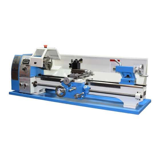
Page 2
(see our website www.preci- sionmatthews.com for support addresses). Your feedback is welcomed! This material was originated by Precision Matthews. No portion of the manual may be reproduced or distributed in any form without the written approval of Quality Machine Tools, LLC.
Section 1 INSTALLATION THESE ARE THE MAIN POINTS TO WATCH OUT FOR! But read the following pages for more information Check oil level in the gearbox and apron before use • Handling the lathe is at least a two-man job. •...
SETTING UP THE LATHE if available. If not, use the most reliable level on hand. Check and adjust level front-to-back across the bed using a matched The PM-1030V is shipped in two packing cases, one for the pair of spacer blocks to clear the Vee tenons on the bed ways. lathe, one for the optional stand.
Page 5
spindle for a few minutes, forward and reverse, at a selec- tion of speeds in both speed ranges (transfer the Vee belt from inner to outer pulley grooves to change speed range). 2. The gearbox should also be run at this time, but first make certain that the leadscrew and feed shaft oilers at the tailstock end have been lubricated.
100 to 2000 rpm. Power requirement is 110 V, 60Hz. The lathes ship fully assembled, approximate net weight 395 lb PM-1030V, 365 lb PM-1022V. A sheet metal stand with two cabinets is available as an option. The spindle has a 1 inch bore, and is unusually short — just 11 inches, ideal for through-spindle work. Long service life is assured by high precision taper-roller spindle bearings, together with hardened and ground bed ways.
Page 7
Everyday precautions • This machine is intended for use by experienced users familiar with met- al-working hazards. • Untrained or unsupervised operators risk serious injury. • Wear ANSI-approved full-face or eye protection at all times when using the machine (everyday eyeglasses are not reliable protection against flying parti- cles).
Page 8
PM-1030V SPECIFICATIONS Width 52 in. x Height 19 in. x Depth 25 in. (full range cross- slide motion) Footprint (excluding handles): Width 52 in. x Depth 19 in. Dimensions, approximate overall, incl. stand Bed length, excluding headstock: 41-1/2 33-3/4 (1030V numbers in black, 1022V this color) Bed width: 5-1/4 in.
The button pops out when twisted clockwise a few degrees. This restores power, but does not activate motor. The PM-1022V and PM-1030V are conventional engine lathes that require little explanation except for specific details — MOTOR CONTROL speed control, thread cutting, and the saddle/cross-slide pow- er feed system.
CHUCK REMOVAL & REPLACEMENT Speed sensor Chucks and faceplates are secured to the PM-1030V spin- Input to the tachometer is from a sensor mounted on the left hand surface of the headstock, Figure 3-4. dle by three threaded studs and nuts, Figures 3-7 and 3-8. A knurled shutter ring allows the chuck to be removed or re-in- stalled with the nuts in place —...
Page 11
Shutter ring open Turned counter-clockwise Knurled shutter ring Figure 3-9 Saddle handwheel CROSS SLIDE & COMPOUND The cross slide and compound, Figure 3-10, both have 10 TPI leadscrews, with 100-division graduated collars. Each division represents a true motion of 0.001”. On the cross-slide dial, only, this shows as 0.002”...
Page 12
Center Locknut post Wave washer Lock handle Thumb Toolpost Tool holder Figure 3-12 Compound at zero degrees Compound clamp ring (1); Compound lock screw (2) Figure 3-14 QCTP with toolholder This style of toolholder is used for rectangular-shank tools up to 1/2" x 1/2".
Page 13
To offset the tailstock for taper turning, loosen the tailstock clamp lever, Figure 3-15, then loosen the clamp screw (M5 set screw) at the tail end of the tailstock. The tailstock can now be moved forward or backward by adjusting the M8 socket head cap screws on either side.
Page 14
ENGAGING THE POWER FEED POWER FEED RATES (Turning & Facing operations) First check for obstructions — Locks OFF? Do not engage at high leadscrew speeds! Figure 3-17 Saddle feed Lever RIGHT and UP Fine feed setup Coarse feed setup 0.0025 0.0035 0.005 0.007...
Page 15
THREAD CUTTING SETUPS — U.S. threads in TPI (threads per inch) Z3 varies, see table below B 12 Z3 40T 50T 55T 65T A 18 A 24 C 36 C 48 Lower gear 9-1/2 11-1/2 Less common threads (not illustrated) B 14 A 28 C 56...
THREAD CUTTING as Figure 3-23. Single-point threads are cut in as many as 10 successive passes, sometimes more, each shaving a little A key fact to remember ... more material off the workpiece. For metric threads the half-nut in the apron must To make the first thread-cutting pass the leadscrew is run at remain engaged throughout the entire process.
Page 18
Figure 3-26 Threading dial visualization for selected U.S. threads GENERAL RULES FOR THE THREADING DIAL Special cases: if the ÷ 2 result is an even whole number, ex- ample 12/2 = 6, there are even more re-engagement choices, If the TPI value gives a whole number when divided by two, see the visualization chart above.
Page 19
STEADY & FOLLOWER RESTS viding support directly ahead of the cutting tool, Figure 3-29. It is secured to the saddle with two 8 mm socket head screws. Short, rigid workpieces mounted in a chuck can typically be machined without additional support. Long, slender workpiec- es need support near the cutting tool.
Section 4 SERVICING THE LATHE Disconnect power before any maintenance operation! Remove all machining debris and foreign objects before lubricating ANYTHING! Use the recommended lubricants or similar. Any oil is better than no oil – but only as a stop gap. GENERAL cess to the drain plug, Figure 4-1.
Page 21
LUBRICATION — APRON DRAIN & REFILL 1. Remove the apron fill plug, Figure 4-3. 2. Locate the drain plug on the underside of the apron casting. 3. Place a drain pan below the drain plug, then remove the plug. 4. Allow the oil to drain completely, then replace the drain plug.
Page 22
ADJUSTMENT — GIB SCREWS ADJUSTMENT — CROSS-SLIDE BACKLASH When alternating between clockwise and counter clockwise rotation, the cross-slide handwheel may move freely a few de- grees but the cross-slide table stays put. Cross-slide lost motion is due to two factors: 1. Too-loose at- tachment of the handwheel attached to the leadscrew, and;...
Page 23
ALIGNING THE LATHE quill. If the centers are aligned, the blade will point squarely front to back. If not, adjust the tailstock offset by a series of very small adjustments. The most important attribute of a properly set up lathe is its If the range of quill motion permits, check the blade align- ability to “machine parallel”, to cut a cylinder of uniform diame- ment at various extensions of the quill.
Section 5 PARTS HEADSTOCK Fig 1 There may be detail differences between this representative drawing and the machine as supplied Dimensions in millimeters Ref Description Part Ref Description Part Spindle Z1046 Locknut Z1060 Key 8 x 45 Z1047 Screw M5 x 10 Z1061 Outer spacer Z1048...
Page 25
EXTERNAL CHANGE GEARS Fig 2 There may be detail differences between this representative drawing and the machine as supplied Ref Description Part Dimensions in millimeters Oiler Φ6 Z1074 Gear axle Z1075 Special C-washer Z1076 Ext. keyed bushing Z1077 Thin spacer washer, special Z1078 T-nut Z1079...
Page 31
COMPOUND Fig 5B Ref Description Part Screw M5 x 40 Z1240 There may be detail differences between this representative drawing Leadscrew nut Z1241 and the machine as supplied Compound clamp ring Z1242 T-bolt M8 x 22 Z1243 Pin 4 x 6 Z1244 Screw M6 x 14 Z1245...
Page 33
BED & TAILSTOCK Fig 6 Ref Description Part Ref Description Part Tailstock quill Z1009 Tailstock base Z1309 Leadscrew nut Z1008 Offset label Z1310 Leadscrew Z1007 Screw M8 x 30 Z1311 Key 4 x 4 x 15 Z1283 Screw M5 x 8 Z1312 Quill slide key Z1010...
Page 34
ELECTRICAL BOX Fig 7 There may be detail differences between this representative drawing and the machine as supplied Ref Description Part Ref Description Part Speed control knob Z1338 Electrical box Z1349 Screw M3 x 6 Z1339 Filter unit Z1350 Nut M4 Z1340 Screw M4 x 14 Z1351...
Page 35
NOTES HOW THE CONTACTOR WORKS ... This is a brushed dc motor. If, and only if, the Direction Switch (F-O-R) is set to either F or RUN MOTOR (green) and STOP MOTOR (red) switches R, the neutral (N) line is connected to the normally open RUN are momentary-type push buttons that return to their MOTOR contact.
Need help?
Do you have a question about the PM-1022V and is the answer not in the manual?
Questions and answers