Table of Contents
Advertisement
Quick Links
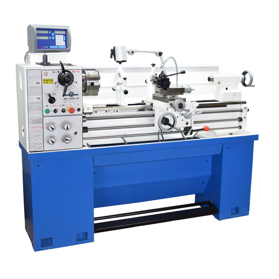
Model PM-1440E-LB Lathe
High precision 3 HP gap-bed machine
2 inch spindle bore
D1-5 camlock spindle mount
40 in. between centers, 14 in. swing over bed, 19-3/4 in. over gap
8 spindle speeds from 70 to 2000 rpm
Full range of Inch and Metric thread cutting
Bidirectional power feed for saddle & cross-slide
Weight, including cast iron stand & coolant system 1800 lb
PM-1440E-LB Shown here with 2-axis DRO (option), 3-jaw chuck, coolant sys-
tem, footbrake, worklight, steadies, wedge-type QC toolpost, cast iron stand
PM-1440E-LB 11-13-17 V1
1
Copyright © October 2017 Quality Machine Tools, LLC
Advertisement
Table of Contents

Related Manuals for Precision matthews PM-1440E-LB


Summary of Contents for Precision matthews PM-1440E-LB
- Page 1 Bidirectional power feed for saddle & cross-slide Weight, including cast iron stand & coolant system 1800 lb PM-1440E-LB Shown here with 2-axis DRO (option), 3-jaw chuck, coolant sys- tem, footbrake, worklight, steadies, wedge-type QC toolpost, cast iron stand PM-1440E-LB 11-13-17 V1...
- Page 2 Section 4. This manual contains essential safety advice on the proper setup, operation, maintenance, and service of the PM-1440E-LB lathe. Failure to read, understand and follow the manual may result in property damage or serious personal injury.
-
Page 3: Section 1 Installation
4. The headstock gear selectors are set for the lowest spindle speed. SETTING UP THE LATHE The PM-1440E-LB is shipped fully assembled in a single Inspect the coolant tank and pump assembly in the RH cabi- packing case. The machine can be lifted in one piece by an net, Figure 1-3. -
Page 4: Safety Interlocks
POWER & OTHER CONNECTIONS or paper. Carefully remove these using a plastic paint scraper, As shipped, the PM-1440E-LB is set for 220 V. If your supply is disposable rags and a light-oil such as WD-40. nominally 240 V, it may be desirable to alter connections to the 24V transformer in the electrical box. -
Page 5: Test Run Procedure
14. Check that the chuck guard switch stops the motor when the guard is swung up. 15. Check that the belt cover interlock stops the motor when the belt cover is removed. PM-1440E-LB 11-13-17 V1 Copyright © October 2017 Quality Machine Tools, LLC... -
Page 6: Section 2 Features & Specifications
40in., swing over the bed 14 in., spindle bore 2 in., internal taper MT6. With a 3 HP motor and an all-up weight of 1800 lb, the PM-1440E-LB is a robust heavy-duty machine. The geared headstock provides 8 spindle speeds from 70 to 2000 rpm. - Page 7 Work holding (typical) 3-jaw chuck, 8 in. 4-jaw chuck, 8 in. Faceplate Center rest (steady rest) capacity Up to 3 in. diameter Follower rest capacity Up to 1 in. diameter PM-1440E-LB 11-13-17 V1 Copyright © October 2017 Quality Machine Tools, LLC...
- Page 8 • Clean the machine routinely – remove chips by brush or vacuum, not com- pressed air (which can force debris into the ways). No list of precautions can cover everything. You cannot be too careful! PM-1440E-LB 11-13-17 V1 Copyright © October 2017 Quality Machine Tools, LLC...
-
Page 9: Section 3 Using The Lathe
(7) Emergency E-Stop button — must be OUT for the lathe to function (8) Jog push-button (9) When set to N as shown, this knob disengages the leadscrew, engages the feed-shaft drive. PM-1440E-LB 11-13-17 V1 Copyright © October 2017 Quality Machine Tools, LLC... -
Page 10: Spindle Speeds
SPINDLE SPEEDS ENGAGING THE POWER FEED The PM-1440E-LB has an eight-speed headstock gearbox (For normal turning and facing operations) with two shift levers, LH and Speed Selection, Figure 3-1. To activate the feed shaft: 1. Set the Direction lever, Figure 3-1... - Page 11 6. For power feeding or U.S. (TPI) thread cutting, bring the saddle at a precise location set by the saddle stop, Figure the larger transposing gear (127T) into mesh with the low- 3-8. PM-1440E-LB 11-13-17 V1 Copyright © October 2017 Quality Machine Tools, LLC...
-
Page 12: Thread Cutting
Figure 3-8 Saddle stop PM-1440E-LB 11-13-17 V1 Copyright © October 2017 Quality Machine Tools, LLC... - Page 13 (using the cross-slide), and the spindle is reversed to bring the saddle back to the starting point. The cross-slide is returned to its former Figure 3-12 Threads per Inch (TPI) PM-1440E-LB 11-13-17 V1 Copyright © October 2017 Quality Machine Tools, LLC...
- Page 14 Lower gear 2.25 The threading dial 1.75 1.25 cannot be used 0.75 0.45 for metric thread cutting — leave the split nut engaged! Figure 3-14 Metric thread pitches (mm) PM-1440E-LB 11-13-17 V1 Copyright © October 2017 Quality Machine Tools, LLC...
- Page 15 TIR in a 4-jaw chuck, not in a 3-jaw unless known to be predictably accurate). The prepared bar can then be installed between centers and indicated along its length. Figure 3-18 Compound lock screw (representative) PM-1440E-LB 11-13-17 V1 Copyright © October 2017 Quality Machine Tools, LLC...
- Page 16 The follower rest is secured to the saddle with two 8 mm socket head screws. Adjust the follower fingers as described for the steady rest. Figure 3-20 Steady rest (representative) Figure 3-21 Follower rest (representative) PM-1440E-LB 11-13-17 V1 Copyright © October 2017 Quality Machine Tools, LLC...
- Page 17 CHUCKS & FACEPLATE The spindle nose on the PM-1440E-LB accepts D1-5 Camlock chucks, faceplates and other work holding devices. A D1-5 chuck or faceplate is held by six threaded studs, each with a D-shape crosscut to engage a corresponding cam in the spindle nose.
- Page 18 Jack out the two taper pins using a hex key. Before re-installing the insert, be certain that all mating surfac- es are scrupulously clean. Set the insert in place, lightly tap in PM-1440E-LB 11-13-17 V1 Copyright © October 2017 Quality Machine Tools, LLC...
-
Page 19: Coolant System
The residue may then be handled like any other waste oil. Figure 3-30 Coolant pump, RH stand cabinet (representative) PM-1440E-LB 11-13-17 V1 Copyright © October 2017 Quality Machine Tools, LLC... -
Page 20: Section 4 Servicing The Lathe
1. Run the lathe for a few minutes to warm the oil if neces- sary. 2. Remove the fill plug on the top surface of the headstock, Figure 4-2 Headstock sight glass & drain plug Figure 4-1. PM-1440E-LB 11-13-17 V1 Copyright © October 2017 Quality Machine Tools, LLC... - Page 21 Replace the drain plug. (representative) Add oil to the halfway mark on the sight glass (about 1 qt). The threading dial may not have the oiler shown here. PM-1440E-LB 11-13-17 V1 Copyright © October 2017 Quality Machine Tools, LLC...
-
Page 22: Gib Adjustment
— appreciable side to side movement — this may be Figure 4-11 Split nut gib screws (representative) corrected by adjusting the gib at the right side of the apron. PM-1440E-LB 11-13-17 V1 Copyright © October 2017 Quality Machine Tools, LLC... - Page 23 2. Wear in the leadscrew nut. Factor #1 is correctable in both the cross-slide and compound. Leadscrew handwheels on the PM-1440E-LB — cross-slide, Figure 4-13B Handwheel attachment compound and tailstock — are attached in a similar way, Fig- ure 4-13.
-
Page 24: Brake Assembly
Tighten the nut as necessary. PM-1440E-LB 11-13-17 V1 Copyright © October 2017 Quality Machine Tools, LLC... - Page 25 0.001” in 3 inches. If the headstock is (say) 10 inches long, this would be Figure B Quick alignment check PM-1440E-LB 11-13-17 V1 Copyright © October 2017 Quality Machine Tools, LLC...
- Page 26 What follows is a general outline. Specific collet, while levering the outer end of the rod (gentle tap- instructions for the PM-1440E-LB follow this section. ping with a non-marring hammer can also be helpful). HEADSTOCK ALIGNMENT METHODS...
- Page 27 Runout should be less than 0.0005" TIR. Figure A2 Headstock attachment screws, RH Figure F Morse taper test bar PM-1440E-LB HEADSTOCK ALIGNMENT Figure A1 is an exaggerated top-down view of what happens if the spindle is not precisely aligned with the lathe bed. This...
-
Page 28: Section 5 Parts
Section 5 PARTS PM-1440E-LB ELECTRICAL SCHEMATIC When pushed ... the E-STOP button remains in, disconnect- ing power, until reset by twisting action. Reverse) switches SQ1/SQ2 must be in the neutral (OFF) state shown here. For electrical continuity the Chuck Guard and Belt Cover must be closed at all times. - Page 29 PM-1440E-LB Electrical box PM-1440E-LB 11-13-17 V1 Copyright © October 2017 Quality Machine Tools, LLC...
- Page 30 Motor control switches Motor control cam PM-1440E-LB 11-13-17 V1 Copyright © October 2017 Quality Machine Tools, LLC...
- Page 31 Stand components There may be detail differences between this representative drawing and the ma- chine as supplied. PM-1440E-LB 11-13-17 V1 Copyright © October 2017 Quality Machine Tools, LLC...
- Page 32 The following schedule refers to the drawings on this page and the preceding page GB1171-74 Belt A813 GB5783-86 Bolt M8×25 GB77-85 Screw M6×12 90S-4 Motor GB1096-79 33-6032 Clamp knob GB97.1-86 Washer 8 32-01107 Pulley PM-1440E-LB 11-13-17 V1 Copyright © October 2017 Quality Machine Tools, LLC...
- Page 33 Motor control lever CL6132-01-38 Spring GB4141.11-84 Knob GB308-84 Steel ball 6 GB70-85 Screw M6×16 6220-2085 Shear pin 33-6045 Bracket GB2089-80 Compression spring 1×6×20 33-6047 Washer GB818-85 Screw M5×6 32-12206A Cover plate PM-1440E-LB 11-13-17 V1 Copyright © October 2017 Quality Machine Tools, LLC...
- Page 34 Headstock (1) RANGE SPEED (RPM) FEED DIRECTION There may be detail differences between this representative drawing and the machine as supplied PM-1440E-LB 11-13-17 V1 Copyright © October 2017 Quality Machine Tools, LLC...
- Page 35 Screw M4×8 32C-04116 Handle (H-L) GB78-85 Set screw M8×8 GB894.1-86 Circlip 30 GB2089-80 Spring 0.6×4.4×16 GB2089-80 Spring 1×6×20 GB78-85 Set screw M8×10 32C-04110 Handle (Feed direction) All dimensions in millimeters PM-1440E-LB 11-13-17 V1 Copyright © October 2017 Quality Machine Tools, LLC...
- Page 36 There may be detail differences between this repre- sentative drawing and the machine as supplied A Spindle D Internal shaft B Internal shaft E Output to C Power input change gears PM-1440E-LB 11-13-17 V1 Copyright © October 2017 Quality Machine Tools, LLC...
- Page 37 Geared shaft (2.25) 32-04210 Gear 51T (2) 32-04209 Gear 43T (2) 32-04221 Spacer 32-04222 Gear 26T (2) 32-04223 Gear 34T (2) 32-04224 Gear 53T (2.25) 32-04225 Plug All dimensions in millimeters PM-1440E-LB 11-13-17 V1 Copyright © October 2017 Quality Machine Tools, LLC...
- Page 38 Not shown: spider assembly (LH end of spindle 105) A Spindle B Internal shaft C Power input D Internal shaft E Output to change gears PM-1440E-LB 11-13-17 V1 Copyright © October 2017 Quality Machine Tools, LLC...
- Page 39 Gasket GB6172-86 Nut M12 32-04205 Gear 32-04507 Oil Seal 32-04239 'E' Shaft 32-04203 Spacer GB70-85 Screw M5×16 32-04202 Spacer GB894.1 Circlip 20 32-04201 Gear 37T All dimensions in millimeters PM-1440E-LB 11-13-17 V1 Copyright © October 2017 Quality Machine Tools, LLC...
- Page 40 0220-2051 Change gear M1.25x56T 33-6025 Sleeve 6220-2057 Change gear M1.25x54T 32C-051 12 Swing Frame 32-05242 Change gear M1.25x30T 32-05228 Setting Bolt CL6132A-15-03 Change gear M1.25x40T All dimensions in millimeters PM-1440E-LB 11-13-17 V1 Copyright © October 2017 Quality Machine Tools, LLC...
- Page 41 Set screw M8x12 GB879-86 Spring pin 5x40 6220-2050 Knob GB2089-80 Spring 1x5x20 GB308-89 Steel ball 6 GB818-85 Cross-head screw M4x8 GB70-85 Screw M5x25 GB879-86 Spring pin 4x3O All dimensions in millimeters PM-1440E-LB 11-13-17 V1 Copyright © October 2017 Quality Machine Tools, LLC...
- Page 42 Gearbox There may be detail differences between this representative drawing and the machine as supplied PM-1440E-LB 11-13-17 V1 Copyright © October 2017 Quality Machine Tools, LLC...
- Page 43 6220-201 5 Spacer 6220-2016 Gear 6220-2017 Gear CM6220-2018 Gear 6220-2019 Sleeve 6220-2020 Gear 6220-2024 Gear GB896-86 Retaining ring 15 6220-2022 Gear 6220-2040B Shift fork 6220-2037B Rack 6220-2039B Shift fork PM-1440E-LB 11-13-17 V1 Copyright © October 2017 Quality Machine Tools, LLC...
- Page 44 There may be detail differences between this repre- sentative drawing and the machine as supplied There may be detail differences between this repre- sentative drawing and the machine as supplied PM-1440E-LB 11-13-17 V1 Copyright © October 2017 Quality Machine Tools, LLC...
- Page 45 Handle T-plate Compression spring Set screw M8 Saddle casting Screw Compound leadscrew Support flange Flange Screw Thrust bearing Cover plate Graduated collar Screw M8 Handle All dimensions in millimeters PM-1440E-LB 11-13-17 V1 Copyright © October 2017 Quality Machine Tools, LLC...
- Page 46 Apron There may be detail differences between this representative drawing and the machine as supplied PM-1440E-LB 11-13-17 V1 Copyright © October 2017 Quality Machine Tools, LLC...
- Page 47 Screw M8×30 GB41-86 Nut M8 GB117-85 Taper pin 8×40 Q/ZG285.3 Drain plug 1/8” 33-4050 Split nut indicator GB1160-89 Sight glass GB879-86 Roll pin 5×35 GB2089-80 Spring All dimensions in millimeters PM-1440E-LB 11-13-17 V1 Copyright © October 2017 Quality Machine Tools, LLC...
- Page 48 Tailstock There may be detail differences between this representative drawing and the machine as supplied Tailstock locking lever not shown PM-1440E-LB 11-13-17 V1 Copyright © October 2017 Quality Machine Tools, LLC...
- Page 49 GB6172-86 Nut M8 32-08101 Tailstock casting 32-08403 Quill clamp block GB97.1-86 Washer GB6170-86 Nut M12 32-08212 Lock screw assembly 32-08105 Base casting 32-08104 Clamp block All dimensions in millimeters PM-1440E-LB 11-13-17 V1 Copyright © October 2017 Quality Machine Tools, LLC...
- Page 50 Screw M6×6 in millimeters GB119-86 Roll pin 3×18 32-10103 Clamp block 32-10203 Collar GB37-85 T-screw M12 32-10204 Jack screw 32-10104 Follow Rest 32-10201 Collar GB70-85 Screw M8×45 32-10401 Contact head PM-1440E-LB 11-13-17 V1 Copyright © October 2017 Quality Machine Tools, LLC...
Need help?
Do you have a question about the PM-1440E-LB and is the answer not in the manual?
Questions and answers