Table of Contents
Advertisement
Quick Links
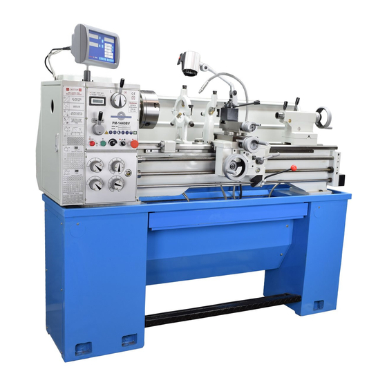
Model PM-1440BV Lathe
Heavy duty VFD gap-bed machine
Continuously variable spindle speed from 40 to 400 & 220 to 1800 rpm
Large bore spindle: 2 inch clearance
D1-5 camlock spindle mount
40 in. between centers, 14 in. swing over bed, 18-3/4 in. over gap
Multi-speed gearbox for full-range screw cutting, TPI & mm pitch
Bidirectional power feed for saddle & cross-slide
Weight, including cast iron stand 1800 lb
PM-1440BV Includes foot brake, coolant system & work light.
Options shown here: 2-axis DRO and quick-change toolpost
(wedge-type).
PM-1440BV v3 2020-10
1
Copyright © 2020 Quality Machine Tools, LLC
Advertisement
Table of Contents

Related Manuals for Precision matthews PM-1440BV


Summary of Contents for Precision matthews PM-1440BV
- Page 1 Multi-speed gearbox for full-range screw cutting, TPI & mm pitch Bidirectional power feed for saddle & cross-slide Weight, including cast iron stand 1800 lb PM-1440BV Includes foot brake, coolant system & work light. Options shown here: 2-axis DRO and quick-change toolpost (wedge-type).
- Page 2 This manual describes PM-1440BV machines as shipped from April 2017. There may be detail differences between your specific machine and the information given here (with little or no impact on functionality). Please email us if you have questions about any aspect of the manual or your machine (see our website www.precisionmatthews.com for support...
-
Page 3: Section 1 Installation
With the lathe in its permanent location, level it using metal shims under the cabinets, or (preferred), install six 500 lb-rated The PM-1440BV is shipped fully assembled in a single pack- leveling mounts in the mounting holes of the two stand cabi- ing case. -
Page 4: Coolant Tank
Use ca- ble ties if necessary. Figure 1-5 Footbrake switch ELECTRICAL CONNECTIONS As shipped, the PM-1440BV is set for 220 Vac single phase Figure 1-3 Chip tray power. Read Initial Checks, below, before connecting power Remove the upper rear cover from the LH cabinet. -
Page 5: Initial Checks
15. Check that the footbrake stops the motor. 16. Return the motor control lever to OFF, mid-travel. Precision Matthews recommends draining and refilling all 17. Shift the motor control lever UP. The spindle should Reverse, clockwise rotation, viewed at the chuck (nose) three gearboxes (Headstock, Saddle Feed and Apron) af- end. -
Page 6: Section 2 Features & Specifications
MODEL PM-1440BV Lathe General information The PM-1440BV is a robust, heavy duty gap-bed lathe designed for day-in, day-out use in production and in the larger model shop. It features a 2 HP motor with variable frequency single-phase/three-phase converter (VFD) giving smoothly variable spindle speeds from 40 to 400 rpm and 220 to 1800 rpm. Power requirement is 220 Vac 1Ø.The lathe ships fully assembled, with foot brake, on cast iron stands (all-up weight 1800 lb). - Page 7 Work holding (typical) 3-jaw chuck, 8 in. 4-jaw chuck, 8 in. Faceplate Center rest (steady rest) capacity Up to 3 in. diameter Follower rest capacity Up to 1 in. diameter PM-1440BV v3 2020-10 Copyright © 2020 Quality Machine Tools, LLC...
- Page 8 • Clean the machine routinely – remove chips by brush or vacuum, not com- pressed air (which can force debris into the ways). No list of precautions can cover everything. You cannot be too careful! PM-1440BV v3 2020-10 Copyright © 2020 Quality Machine Tools, LLC...
-
Page 9: Section 3 Using The Lathe
Section 1 What is not in this section ... The PM-1440BV is a conventional engine lathe that requires STOP the motor before changing speed little explanation except for details specific to this particular RANGE, H to L, L to H model —... - Page 10 Small change gears can be installed with the hub facing out, dle motion is approximately 3 times cross-slide motion. as Figure 3-8, lower gear. For the upper change gear, only, this does not apply to gears larger than 42 teeth. PM-1440BV v3 2020-10 Copyright © 2020 Quality Machine Tools, LLC...
-
Page 11: Thread Cutting
For the removed portion substi- tute a separate plain collar. This will allow the transposing gear to be installed either way with no additional effort. Figure 3-7 Feedshaft clutch PM-1440BV v3 2020-10 Copyright © 2020 Quality Machine Tools, LLC... - Page 12 Figure 3-11. Single-point threads are cut in 10 or more successive passes, each shaving 0.75 0.45 a little more material off the workpiece. Figure 3-10 Metric thread pitches (mm) PM-1440BV v3 2020-10 Copyright © 2020 Quality Machine Tools, LLC...
- Page 13 = 5, 14/2 = 7, re-engage at any line on the dial, but NOT mid-way between the lines. If in doubt, re-engage on the start line! PM-1440BV v3 2020-10 Copyright © 2020 Quality Machine Tools, LLC...
- Page 14 Conversely, to install a taper tool make certain that the quill is out far enough to allow firm seating. PM-1440BV v3 2020-10 Copyright © 2020 Quality Machine Tools, LLC...
- Page 15 (snug, but not fully tightened). Jack the insert to the right with the pusher Figure 3-17 Steady rest (representative) screws to close the gap, if any, between the ground surfaces PM-1440BV v3 2020-10 Copyright © 2020 Quality Machine Tools, LLC...
-
Page 16: Coolant System
The residue may then be handled like any other waste oil. Representative insert Figure 3-19 Gap insert Figure 3-20 Coolant pump assembly, RH stand cabinet PM-1440BV v3 2020-10 Copyright © 2020 Quality Machine Tools, LLC... - Page 17 CHUCKS & FACEPLATE The spindle nose on the PM-1440BV accepts D1-5 Camlock chucks, faceplates and other work holding devices. A D1-5 chuck or faceplate is held by six threaded studs, each with a D-shape crosscut to engage a corresponding cam in the spindle nose, Figures 3-21, 3-22.
- Page 18 12 o’clock, Figure 3-24, then remove the chuck. If the chuck does not come free, try tapping the backplate gently with a soft (dead blow) mallet. PM-1440BV v3 2020-10 Copyright © 2020 Quality Machine Tools, LLC...
-
Page 19: Section 4 Servicing The Lathe
1. Run the lathe a few minutes to warm the oil if necessary. 2. Open the drive train cover left of the headstock. 3. Remove the fill plug on the top surface of the headstock, Figure 4-3 Headstock sight glass PM-1440BV v3 2020-10 Copyright © 2020 Quality Machine Tools, LLC... - Page 20 (about 1 qt). Figure 4-7 Saddle, cross slide and compound oilers A 9th oiler, not shown, is above the saddle handwheel Figure 4-5 Apron gearbox fill plug Figure 4-8 Tailstock oilers PM-1440BV v3 2020-10 Copyright © 2020 Quality Machine Tools, LLC...
-
Page 21: Gib Adjustment
Factor #1 is correctable in both the cross-slide and compound. Figure 4-9 Cross slide & compound front gib screws Leadscrew handwheels on the PM-1440BV — cross-slide, compound and tailstock — are attached in a similar way, Fig- ure 4-13. The handwheel is locked to the leadscrew shaft by a key (not shown). -
Page 22: Foot Brake
Section 5 electrical schematic. Figure 4-13B Handwheel attachment Figure 4-16 Foot brake switch Figure 4-14 Cross slide leadscrew nut (representative) PM-1440BV v3 2020-10 Copyright © 2020 Quality Machine Tools, LLC... -
Page 23: Drive Belt Adjustment
Figure 4-17 Test belt tension Figure 4-18 Motor frame bolts Two of three; the third bolt is at the pulley end of the motor (open the external gear cover for access). PM-1440BV v3 2020-10 Copyright © 2020 Quality Machine Tools, LLC... - Page 24 0.001” in 3 inches. If the headstock is (say) 10 inches long, this would be corrected by tapping one end of the headstock forward or back Figure B Quick alignment check PM-1440BV v3 2020-10 Copyright © 2020 Quality Machine Tools, LLC...
- Page 25 4. If there is a significant difference in TIR* from (1) to (2), try instructions for the PM-1440BV follow this section. to correct this by loosening, then re-tightening the chuck/ collet, while levering the outer end of the rod (gentle tap- ping with a non-marring hammer can also be helpful).
- Page 26 Runout should be less than 0.0005" TIR. Figure A2 Headstock attachment screws, RH Figure F Morse taper test bar PM-1440BV HEADSTOCK ALIGNMENT Figure A1 is an exaggerated top-down view of what happens if the spindle is not precisely aligned with the lathe bed. This...
-
Page 27: Section 5 Parts
— motor control lever down, spindle goes backward (cw, viewed from tailstock) Upper electrical box KM3, KA2, KA1 and KA0 are all low voltage, 24Vac relays (contactors) PM-1440BV v3 2020-10 Copyright © 2020 Quality Machine Tools, LLC... - Page 28 Brake resistor Lower electrical box (VFD) PM-1440BV v3 2020-10 Copyright © 2020 Quality Machine Tools, LLC...
- Page 29 PM-1440BV v3 2020-10 Copyright © 2020 Quality Machine Tools, LLC...
- Page 30 STAND COMPONENTS Fig 1 There may be detail differences between this representative drawing and the machine as supplied PM-1440BV v3 2020-10 Copyright © 2020 Quality Machine Tools, LLC...
- Page 31 Z3046 Shaft Z3069 Coolant container Z3047 RH stand casting Z3070 Socket head screw M10×30 Z3048 Lift hole cover Z3071 Hexagon nut M10 Z3049 Coolant return chute Z3072 Dimensions in millimeters PM-1440BV v3 2020-10 Copyright © 2020 Quality Machine Tools, LLC...
- Page 32 BED COMPONENTS Fig 2 There may be detail differences between this representative drawing and the machine as supplied PM-1440BV v3 2020-10 Copyright © 2020 Quality Machine Tools, LLC...
- Page 33 Z3104 Spring 6×1×25 Z3141 Key 4×50 Z3105 Screw M8×8 Z3142 Bushing Z3106 Screw M6×10 Z3143 Screw M8×8 Z3107 Sleeve Z3144 Spring 6×1×15 Z3108 Ball bearing 51104 Z3145 Dimensions in millimeters PM-1440BV v3 2020-10 Copyright © 2020 Quality Machine Tools, LLC...
- Page 34 Thrust bearing 6003-Z Z3150 Key 5×14 Z3159 Shouldered bushing Z3151 Socket head screw Z3160 Gear quadrant Z3152 Washer Z3161 Nut M12 Z3153 Change gear (lower) Z3162 T-bolt Z3154 Dimensions in millimeters PM-1440BV v3 2020-10 Copyright © 2020 Quality Machine Tools, LLC...
- Page 35 Stud Z3193 Sight glass A12 Z3194 Skt head screw M6×25 Z3195 Top plate Z3196 Fill/drain plugs M16×1.5 Z3197 Copper washer 16 Z3198 Plug Z3199 Dimensions in millimeters PM-1440BV v3 2020-10 Copyright © 2020 Quality Machine Tools, LLC...
- Page 36 HEADSTOCK COMPONENTS Fig 5 There may be detail differences between this representative drawing and the machine as supplied PM-1440BV v3 2020-10 Copyright © 2020 Quality Machine Tools, LLC...
- Page 37 Cover plate Z3228 Washer Z3262 Gasket Z3229 Socket head screw M5×16 Z3263 Ball bearing 6204 Z3230 Collar Z3264 Washer Z3231 Gasket Z3265 Gear Z3232 Gear Z3266 Gear Z3233 Dimensions in millimeters PM-1440BV v3 2020-10 Copyright © 2020 Quality Machine Tools, LLC...
- Page 38 Steel ball 6 Z3273 Front plate Z3284 Spring 6×1×25 Z3274 Gasket Z3285 Screw M8×8 Z3275 Screw M4×6 Z3286 Washer 6 Z3276 RH cover Z3287 Socket head screw M6×12 Z3277 LH cover Z3288 PM-1440BV v3 2020-10 Copyright © 2020 Quality Machine Tools, LLC...
- Page 39 FEED GEARBOX CONTROLS Fig 6 There may be detail differences between this representative drawing and the machine as supplied PM-1440BV v3 2020-10 Copyright © 2020 Quality Machine Tools, LLC...
- Page 40 Z3355 Key 4×18 Z3320 Shift fork D Z3356 Gasket Z3321 Rack D Z3357 End cover Z3322 Screw M5×8 Z3358 Cover plate Z3323 O-ring 12×1.9 Z3359 Gasket Z3324 Dimensions in millimeters PM-1440BV v3 2020-10 Copyright © 2020 Quality Machine Tools, LLC...
- Page 41 APRON Fig 8 PM-1440BV v3 2020-10 Copyright © 2020 Quality Machine Tools, LLC...
- Page 42 Spacer Z3435 Rivet 2×5 Z3396 Key 5×5×20 Z3436 Drain plug Z3397 Shaft Z3437 Split nut indicator Z3398 Socket head screw M8×30 Z3438 Sight glass A20 Z3399 Taper pin 8×40 Z3439 PM-1440BV v3 2020-10 Copyright © 2020 Quality Machine Tools, LLC...
- Page 43 CROSS SLIDE & SADDLE Fig 9 There may be detail differences between this representative drawing and the machine as supplied PM-1440BV v3 2020-10 Copyright © 2020 Quality Machine Tools, LLC...
- Page 44 Wiper clamp plate Z3484 Rubber wiper, LH Z3461 Rubber wiper Z3485 Socket head screw M10×45 Z3462 Screw M8×16 Z3486 Saddle casting Z3463 Screw M6×12 Z3487 Gib screw Z3464 Dimensions in millimeters PM-1440BV v3 2020-10 Copyright © 2020 Quality Machine Tools, LLC...
- Page 45 Handwheel Z3512 Handle, short Z3513 Shoulder bolt Z3514 Lock screw M6×25 Z3515 Flange screw Z3516 Shoulder bolt Z3517 Handle, long Z3518 Screw M6×16 Z3519 Gib screw Z3520 Dimensions in millimeters PM-1440BV v3 2020-10 Copyright © 2020 Quality Machine Tools, LLC...
- Page 46 Roll pin 4×50 Z3549 Base Z3550 Skt head screw M6x40 Z3551 Special washer Z3552 Spring Z3553 Special washer Z3554 Clamp base Z3555 Washer 16 Z3556 Nut M16 Z3557 Dimensions in millimeters PM-1440BV v3 2020-10 Copyright © 2020 Quality Machine Tools, LLC...
- Page 47 Z3570 Steady rest casting Z3571 Nut M12 Z3572 Washer 12 Z3573 Screw M6X6 Z3574 Clamp base Z3575 Screw M12X65 Z3576 Follower rest casting Z3577 Screw M8X46 Z3578 Dimensions in millimeters PM-1440BV v3 2020-10 Copyright © 2020 Quality Machine Tools, LLC...
Need help?
Do you have a question about the PM-1440BV and is the answer not in the manual?
Questions and answers