Advertisement
Table of Contents
- 1 Section 1 Installation
- 2 Power Connection
- 3 Initial Checks
- 4 Section 2 Features & Specifications
- 5 Section 3 USING the LATHE
- 6 Jog Feature
- 7 Thread Cutting
- 8 Coolant System
- 9 Section 4 SERVICING the LATHE
- 10 Gib Adjustment
- 11 Brake Assembly
- 12 Drive Belt Adjustment
- 13 Section 5 Parts
- 14 Electrical Connections
- Download this manual
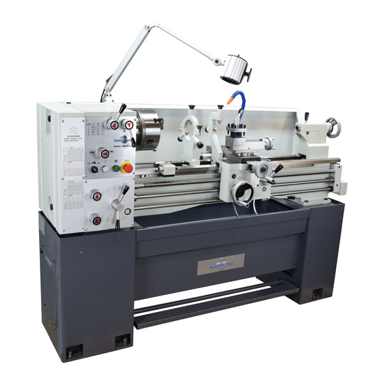
Model PM-1440GT Lathe
Ultra High precision gap-bed lathe, with coolant system
Short spindle length, large bore: 15-1/2 long x 2 inch bore
D1-5 camlock spindle mount
40 in. between centers, 14 in. swing over bed, 20-3/4 in. over gap
12 spindle speeds from 50 to 2000 rpm
Multi-speed gearbox for full-range screw cutting, TPI & MM pitch
Bidirectional power feed for saddle & cross-slide
Weight, including stand & coolant system 1750 lb
PM-1440GT Shown with optional work
light, chuck and micrometer saddle stop
The PM-1440GT lathe is manufactured in Taiwan
1
PM-1440GT v9 2020-10
Copyright © 2020 Quality Machine Tools, LLC
Advertisement
Table of Contents

Related Manuals for Precision matthews PM-1440GT


Summary of Contents for Precision matthews PM-1440GT
- Page 1 Bidirectional power feed for saddle & cross-slide Weight, including stand & coolant system 1750 lb PM-1440GT Shown with optional work light, chuck and micrometer saddle stop The PM-1440GT lathe is manufactured in Taiwan PM-1440GT v9 2020-10 Copyright © 2020 Quality Machine Tools, LLC...
- Page 2 This manual contains essential safety advice on the proper setup, operation, maintenance, and service of the PM-1440GT lathe. Failure to read, understand and follow the manual may result in property damage or serious personal injury. There are many alternative ways to install and use a lathe. As the owner of the lathe you are solely responsible for its proper installation and safe use.
-
Page 3: Section 1 Installation
With the machine in its permanent location, lower it so that its height adjustment bolts rest on the six supplied cast iron level- The PM-1440GT is shipped fully assembled in a single pack- ing mounts, Figure 2. ing case. The machine can be lifted in one piece by an over- head hoist or forklift with slings and/or chains, all items rated for a total weight of at least 1-1/2 tons. -
Page 4: Power Connection
CLEANUP POWER CONNECTION Metal surfaces may have been protected by thick grease and/ As shipped. the PM-1440GT is set for 220 V single or three- or paper. Carefully remove these using a plastic paint scraper, phase. disposable rags and a light-oil such as WD-40. - Page 5 — see Section 3 for power feed directions. Precision Matthews recommends draining and refilling all three gearboxes (Headstock, Saddle Feed and Apron) af- ter approximately 20 hours of initial run time. Lubricants are specified in Section 4.
-
Page 6: Section 2 Features & Specifications
General information The PM-1440GT is a high precision gap-bed lathe. With an all-up weight of 1750 lb, plus 12 spindle speeds from 50 to 2000 rpm, it is a robust heavy-duty machine designed for day-in, day-out use in production and in the larger model shop. - Page 7 Work holding (typical) 3-jaw chuck, 8 in. 4-jaw chuck, 8 in. Faceplate Center rest (steady rest) capacity Up to 3 in. diameter Follower rest capacity Up to 1 in. diameter PM-1440GT v9 2020-10 Copyright © 2020 Quality Machine Tools, LLC...
- Page 8 • Clean the machine routinely – remove chips by brush or vacuum, not com- pressed air (which can force debris into the ways). No list of precautions can cover everything. You cannot be too careful! PM-1440GT v9 2020-10 Copyright © 2020 Quality Machine Tools, LLC...
-
Page 9: Section 3 Using The Lathe
Section 3 USING THE LATHE What is not in this section ... The PM-1440GT is a conventional engine lathe that requires little explanation except for details specific to this particular model — speed selection, thread cutting, and the saddle/ cross-slide power feed system. Because the user is assumed to be familiar with general purpose metal lathes, this section contains very little tutorial. -
Page 10: Jog Feature
Figure 3-5 Camlock stud CHUCKS & FACEPLATE TO INSTALL A CHUCK The spindle nose on the PM-1440GT accepts D1-5 Camlock chucks, faceplates and other work holding devices. Disconnect the 220V supply from the lathe! A D1-5 chuck or faceplate is held by six threaded studs, each... - Page 11 If there are no visible problems, the stud in question may need adjustment: • Remove the stop screw from the stud. Figure 3-9 Cross-slide and compound dials PM-1440GT v9 2020-10 Copyright © 2020 Quality Machine Tools, LLC...
- Page 12 The rate of power feed relative to spindle speed is set by the lower lever on the gearbox, W-X-Y-Z, together with the "speed doubler" knobs A-B and C-D. Feed rates are listed on the fol- lowing page. Figure 3-10 Tailstock PM-1440GT v9 2020-10 Copyright © 2020 Quality Machine Tools, LLC...
- Page 13 (two M6 socket head screws on the under- side secure the clamp plate to the block). Make certain that the stop rod seats firmly on the saddle casting. Figure 3-15 Feedshaft clutch Figure 3-13 Saddle stop PM-1440GT v9 2020-10 Copyright © 2020 Quality Machine Tools, LLC...
-
Page 14: Thread Cutting
In this configuration, not shown, the spacer smaller gear. This will require the transposing gear pair to be bushing is inside the lower gear. repositioned. The procedure for this is: PM-1440GT v9 2020-10 Copyright © 2020 Quality Machine Tools, LLC... - Page 15 For all other TPI numbers every engagement, including the Figure 3-21 Setting up the compound for 30 infeed first, must at the point where a specific line on the threading PM-1440GT v9 2020-10 Copyright © 2020 Quality Machine Tools, LLC...
- Page 16 If in doubt, re-engage on the start line! Figure 3-23 Threading dial visualization for selected U.S. threads Minimize wear by swinging the dial indicator assembly away from the leadscrew when not in use PM-1440GT v9 2020-10 Copyright © 2020 Quality Machine Tools, LLC...
- Page 17 Make certain that all three fingers are freely adjustable by thumbwheel. If not, loosen and re-lock the set screws (ar- rowed). Raise the two lower fingers to just touch the workpiece Figure 3-27 Saddle, cross-slide and compound locks PM-1440GT v9 2020-10 Copyright © 2020 Quality Machine Tools, LLC...
-
Page 18: Coolant System
(a visible parting line is acceptable, but a discontinuity that snags the saddle is not). If a satisfactory join cannot be achieved, it may be necessary to remove and reinstall the insert from scratch. PM-1440GT v9 2020-10 Copyright © 2020 Quality Machine Tools, LLC... - Page 19 This is a toolroom-quality fixture that can be retrofitted to reamers, many of which have center holes drilled both ends. any PM-1440GT lathe manufactured later than 2016. It is a [Center-to-center alignment is not an issue if the reference self-contained, center-pivoted design that is attached by a sin- item can be held in a chuck, in which case it is only necessary gle clamp at any point along the lathe bed.
- Page 20 Setting the taper angle No matter what method you use to set the taper angle, bear in mind that all dial indicating should be done in one direction only to eliminate backlash. PM-1440GT v9 2020-10 Copyright © 2020 Quality Machine Tools, LLC...
-
Page 21: Section 4 Servicing The Lathe
Take time to prepare. 4 quarts is a lot of oil to clean up! 1. Remove the belt cover, left of the headstock. 2. Remove the fill plug on the top surface of the headstock, Figure 4-3 Headstock sight Figure 4-1. glass PM-1440GT v9 2020-10 Copyright © 2020 Quality Machine Tools, LLC... - Page 22 4-7,and allow the apron to empty completely. Replace the drain plug. Add oil to the halfway mark on the sight glass (about 1 qt). Figure 4-9 Tailstock oiler Figure 4-6 Apron gearbox fill plug PM-1440GT v9 2020-10 Copyright © 2020 Quality Machine Tools, LLC...
-
Page 23: Gib Adjustment
It comprises a support bar, attached to the carriage, and two Figure 4-12 Saddle gib assembly separate gib strips each with two adjusting screws. Figure 4-10 Cross-slide & compound front gib screws Figure 4-11 Cross-slide & compound back gib screws PM-1440GT v9 2020-10 Copyright © 2020 Quality Machine Tools, LLC... - Page 24 Factor #1 is correctable in both the cross-slide and compound. Leadscrew handwheels on the PM-1440GT — cross-slide, compound and tailstock — are attached in a similar way, Fig- ure 4-13. The handwheel is locked to the leadscrew shaft by a key (not shown).
-
Page 25: Brake Assembly
Loosen the two hex-head bolts securing the motor frame to the headstock, Figure 4-18. Loosen the lock nuts on the pusher screws, Figure 4-19, then adjust the screws to achieve the de- sired belt tension. Re-tighten the lock nuts. PM-1440GT v9 2020-10 Copyright © 2020 Quality Machine Tools, LLC... - Page 26 0.001” in 3 inches. If the headstock is (say) 10 inches long, this would be corrected by tapping one end of the headstock forward or back Figure B Quick alignment check PM-1440GT v9 2020-10 Copyright © 2020 Quality Machine Tools, LLC...
- Page 27 4. If there is a significant difference in TIR* from (1) to (2), try instructions for the PM-1440GT follow this section. to correct this by loosening, then re-tightening the chuck/ collet, while levering the outer end of the rod (gentle tap- ping with a non-marring hammer can also be helpful).
- Page 28 Runout should be less than 0.0005" TIR. Figure A2 Headstock attachment screws, RH Figure F Morse taper test bar PM-1440GT HEADSTOCK ALIGNMENT Figure A1 is an exaggerated top-down view of what happens if the spindle is not precisely aligned with the lathe bed. This...
-
Page 29: Section 5 Parts
Section 5 PARTS Model PM-1440GT ELECTRICAL SCHEMATIC PM-1440GT v9 2020-10 Copyright © 2020 Quality Machine Tools, LLC... - Page 30 Motor direction (following page) 5A fuse Power switching contactors COOLANT FORWARD REVERSE Transformer Overload Overload Transformer 2 x 25A fuses 24Vac breaker breaker (coolant (spindle (not installed in relay motor) motor) some models) PM-1440GT v9 2020-10 Copyright © 2020 Quality Machine Tools, LLC...
-
Page 31: Electrical Connections
For reverse jog, move the other #5 wire to the #6 terminal. DRO power Low-wattage 110Vac power is available at R1, S1 on the upper terminal strip, preceding page. PM-1440GT v9 2020-10 Copyright © 2020 Quality Machine Tools, LLC... - Page 32 Z4760 Coolant pump, 1/8 HP Z4773 Lever Z4748 Cap screw M8 x 20 Z4761 Coolant hose assembly Z4774 Collar Z4749 Cap screw M8 x 20 Z4762 Set screw M6 Z4534 PM-1440GT v9 2020-10 Copyright © 2020 Quality Machine Tools, LLC...
- Page 33 Cap screw M10 x 40 Z4795 Z4819 End block Z4784 Cap screw M10 x 35 Z4796 Knob Z4820 Collar Z4785 Lever Z4747 Bushing Z4821 Switch box Z4786 Lever Z4748 Screw M6×16 Z4822 PM-1440GT v9 2020-10 Copyright © 2020 Quality Machine Tools, LLC...
- Page 34 Z4863 E Shaft Z4825 Feed dir'n control T Z4830 Ball-spring-screw Z4864 Gear M2: 42T+42T, Z4826 Shift fork Z4831 Set screw M6 x 8 Z4865 Washer Z4827 Shaft Z4832 Screw Z4866 PM-1440GT v9 2020-10 Copyright © 2020 Quality Machine Tools, LLC...
- Page 35 Gear M2: 30T Z4881 Retaining ring Z4899 Plug Z4882 Retaining ring Z4900 Flange Z4883 Key 8 x 40 mm Z4901 Brake shoe assembly Z4884 Key 8 x 22 mm Z4902 PM-1440GT v9 2020-10 Copyright © 2020 Quality Machine Tools, LLC...
- Page 36 Roll pin 5 x 40 mm Z4859 Ball-spring-screw Z4860 Knob Z4861 Roll pin 5 x 25 mm Z4862 Retaining ring Z4863 Ball-spring-screw Z4864 Set screw M6 x 8 Z4865 Screw Z4866 Dimensions in millimeters PM-1440GT v9 2020-10 Copyright © 2020 Quality Machine Tools, LLC...
- Page 37 Z4936 Washer Z4948 End cover Z4937 Key 5 x 18 Z4949 Stud Z4938 Key 5 x 18 Z4950 Stud Z4939 Data plate (US) Z4951 Z4940 Screw Z4952 Dimensions in millimeters PM-1440GT v9 2020-10 Copyright © 2020 Quality Machine Tools, LLC...
- Page 38 Z4984 Shifter fork Z4972 Sight glass Z4985 Screw Z4973 Gasket Z4986 Cap screw M6 x 30 Z4974 C-D selector knob Z4987 Ball/spring/set screw Z4975 Front panel Z4988 Dimensions in millimeters PM-1440GT v9 2020-10 Copyright © 2020 Quality Machine Tools, LLC...
- Page 39 Gear M2: 27T Z4998 Retaining ring Z5029 Gear assy 14DP1 Z4993 Gear M2: 18T Z4999 Oil fill plug Z5030 Flange Z4994 Gear M2: 36T Z5000 Cap screw M8 x 10 Z5031 PM-1440GT v9 2020-10 Copyright © 2020 Quality Machine Tools, LLC...
- Page 40 Ref Description Part Key 5 x 10 mm Z4976 O-ring Z4977 Roll pin 5 x 40 mm Z4978 Roll pin 5 x 30 mm Z4979 Knob Z4980 Ball/spring/set screw Z4981 PM-1440GT v9 2020-10 Copyright © 2020 Quality Machine Tools, LLC...
- Page 41 Key 5 x 18 mm Z5083 Set screw M8 x 10 Z5084 Retaining ring Z5085 There may be detail differences between this representative drawing and the machine as supplied Dimensions in millimeters PM-1440GT v9 2020-10 Copyright © 2020 Quality Machine Tools, LLC...
- Page 42 Saddle gib, front Z5090 Gear M2: 13T Z5097 Set screw Z5123 Salle lock screw Z5091 Leadscrew Z5098 Washer Z5124 Saddle lock plate Z5092 Leadscrew nut Z5099 Cap screw M6 x 12 Z5125 PM-1440GT v9 2020-10 Copyright © 2020 Quality Machine Tools, LLC...
- Page 43 Leadscrew nut Z5130 Locknut Z5137 Steel ball & spring Z5157 Leadscrew Z5131 Spring Z5138 Set screw M6 x 16 Z5158 Flange Z5132 Detent plunger Z5139 Set screw M6 x 16 Z5159 PM-1440GT v9 2020-10 Copyright © 2020 Quality Machine Tools, LLC...
- Page 44 Z5163 Set screw Z5172 Collar Z5164 Roll piin Z5173 Thumb nut Z5165 Roll pin Z5174 Cone point Z5166 Traveler casting Z5175 Hinge clamp screw Z5167 Screw Z5176 Thumb nut Z5168 PM-1440GT v9 2020-10 Copyright © 2020 Quality Machine Tools, LLC...
- Page 45 Tailstock clmp collar Z5190 Lock screw M6 x 16 Z5206 Graduated collar Z5183 Tailstock clmp camshaft Z5191 Oiler Z5207 Handwheel Z5184 Tailstock clmp stud Z5192 Cap screw M5 x l6 Z5208 PM-1440GT v9 2020-10 Copyright © 2020 Quality Machine Tools, LLC...
Need help?
Do you have a question about the PM-1440GT and is the answer not in the manual?
Questions and answers
installing single phase 220 v on the 14 40gt is not clear
To install a single-phase 220V power supply on the Precision Matthews PM-1440GT:
1. Use a 220V, 60Hz, single-phase (1φ) power source.
2. Do not use extension cords.
3. Connect the two hot wires from the 240V single-phase supply to L1 and L3 terminals on the machine.
4. Leave the L2 terminal unconnected.
5. Ensure the machine is on a firm footing.
6. Before powering on, confirm the chuck camlocks are tight, no wrench is left in the chuck, saddle and cross-slide are at mid-travel, and power feeds are disengaged.
This setup allows the lathe to operate correctly using single-phase 220V.
This answer is automatically generated