
Related Manuals for FUTABA FMT-02


Summary of Contents for FUTABA FMT-02
- Page 1 14-Channel Digital Proportional R/C System INSTRUCTION MANUAL 1M23Z04502 Technical updates and additional programming examples available at: http://www.futaba-rc.com/faq Entire Contents © 2016...
- Page 2 INTRODUCTION..........4 ...... 41 ............69 <Introduction>...
- Page 3 *The gray part isn't used for a multicopter. *The gray part isn't used for a multicopter............93 ..........99 <Introduction>...
- Page 4 Thank you for purchasing a Futaba FASSTest-2.4GHz FMT-02 series digital proportional R/ manual carefully. *FASSTest: Futaba Advanced Spread Spectrum Technology extend system telemetry subject to change without notice. FUTABA Corporation of America problems or service needs. the systems sold in North America only. Products purchased elsewhere may vary. Always contact your region’s support center for assistance.
- Page 5 The responsible party of this device compliance is: FUTABA Corporation of America The RBRC. SEAL on the nickel-cadmium battery contained in Futaba products indicates that Futaba Corporation is voluntarily participating in an industry-wide taken out of service within the United States. The RBRC. program provides a convenient alternative to placing used nickel-cadmium batteries into the trash or You may contact your local recycling center for information on where to return the spent battery.
- Page 6 Have regular maintenance performed. Although your FMT-02 protects the model memories recommend sending your system to the Futaba Service Center annually during your non- of Model Aeronautics. programs and insured newcomer training are available. Contact the AMA at the address or toll- free phone number below.
- Page 7 Use of this product with other than models may be restricted by Export and Trade Control Regulations. 3. Modification, adjustment, and parts replacement Futaba is not responsible for unauthorized modification, adjustment, or replacement of parts on this product. No part of this manual may be reproduced in any form without prior permission.
- Page 8 ■ Near another radio control flying field. ■ Near or above people. ■ Near homes, schools, hospitals or other places where people congregate. ■ Near high voltage lines, high structures, or communication facilities. ■ Flying behind buildings or other large structures will not only cause you to lose sight of the aircraft, but ■ If the power switch is turned on/off in the opposite also degrade the RF link performance and cause loss of order, the propeller may rotate unexpectedly and cause control. a serious injury. ■ Also always observe the above order when setting the fail safe function. ■ In particular, normally set the throttle channel to idle. ■ Maximum low throttle: Direction in which the engine For a helicopter, set the throttle channel to maintain a or motor runs at the slowest speed or stops. hover. ■ Erroneous input during flight is extremely dangerous. ■ Low battery capacity will cause loss of control and a ■ Unexpected high speed rotation of the engine may crash. cause a serious injury. ■ Erroneous separate antenna input during flight is extremely dangerous. ...
- Page 9 cause a fire, combustion, rupture, or liquid leakage. ■ Use the special charger by connecting it to a proper When quick charging, do not charge the battery above power outlet. ■ Do not charge the battery while riding in a vehicle. Vibration will prevent normal charging. ■ The liquid can cause blindness. ■ Doing so may result burns. ■ Doing so may cause electric shock or injury. ■ Not doing so may cause combustion. ■ Doing so may cause electric shock or a burn. ■ Consult a doctor. The liquid can cause skin damage. ■ Continued use may cause fire, combustion, generation of heat, or rupture. ■ Doing so may cause fire, combustion, generation of ■ Short circuit of the terminals may cause combustion, heat, rupture, or liquid leakage. generation of heat or rupture. ■ The battery memory effect will substantially shorten the battery life even if it is recharged. ■ Doing so will degrade the battery performance. An ambient temperature of 10 ℃ to 30 ℃ (50F to 86F) is ideal for charging.
- Page 10 The data recorded on the SD card cannot be ・ Where the humidity is high compensated regardless of the contents or cause of ・ Where the temperature difference is severe the trouble or obstruction. ・ Where it is very dusty Futaba does not perform data restoration or recovery ・ Where the card will be exposed to shock and vibration work. ・ Near speakers and other magnetic devices Storage and Disposal Precautions ■ The connector doesn't put dust.
- Page 11 FMT-02 is operated by a 6.0 V/1,800 mAh Nickel-Metal Hydride battery. SD card (Secure Digital memory card) (Not included) Model data can be saved to an SD card (SD:32MB-2GB SDHC:4GB-32GB). When FMT-02 transmitter Edit button Two edit buttons are provided, and the operating screen can be immediately “Returned” to the HOME screen during operation.
- Page 12 Weight: 0.38 oz. (10.9g) (*1) When using ESC's make sure that the regulated output capacity meets your usage application. Note: The battery in the FMT-02 transmitter is not connected to the battery connector at initial. Please connect the battery connector before use.
- Page 13 01RM] [RPM sensor optical type : SBS-01RO] [GPS sensor : SBS-01G] [Voltage sensor : SBS- 01V] [S.BUS servo sensor : SBS-01S] • Neckstrap - a neckstrap may be connected to your FMT-02 system to make it easier to handle and • Y-harnesses, servo extensions, hub, etc - Genuine Futaba extensions and Y-harnesses, including a heavy-duty version with heavier wire, are available to aid in your larger model and other installations.
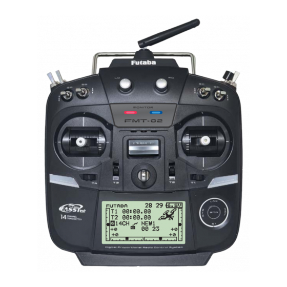
- Page 14 Transmitter controls FMT-02B; Antenna separate type ) * <Before Use>...
- Page 15 Throttle stick warning Self neutral type(This transmitter) Ratchet type(General transmitter) A throttle stick returns A throttle stick neutrally by a spring. doesn't return neutrally. Throttle stick: Motor or engine power is controlled. WARNING You cannot use the throttle stick of self-neutral type for RC airplane, RC helicopter, and certain multi-copter. It's very dangerous if Engine / Motor becomes middle-speed by self-return. It's necessary to change the stick to the ratchet type if using it for RC airplane and RC helicopter. Throttle stick position warning Release of the throttle position warning Power ON LINKAGE MENU 2/2 ⇒ WARNING ⇒ THR POS. ⇒ OFF (Warning)...
- Page 16 90° 90° Monitor LED display Low power The status of the transmitter is displayed by LED at the bottom left and right sides of the "FMT-02" logo. High power High power LED (Left) Displays the "non-default condition" warning. • Blinking...
- Page 17 Digital Trim LS (Left), RS (right): The slide lever LS and RS offer analog input. *The FMT-02 transmitter beeps when the lever comes to the center. *You can select a slide lever and set the movement direction on the setting screen of mixing functions.
- Page 18 Touch sensor operation Data input operation is performed using the touch sensor. SensorTouch™ operation Condition Working • Short 'tap' If the screen has more than one page. (Ex. P-MIX screen) The cursor moves to the top of next page. If the screen have only one (1) page. The cursor moves to the top of page.
- Page 19 1. Hold the lever head "B" and turn the lever Note: head "A" counter-clockwise. The lock will be released. the RTN button. The sensors may mis-read your touch as 2. Turn the lever-head "A" clockwise as you a reverse rotation if the circle is smaller, or performed on hold the lever-head "B"...
- Page 20 4. Use a small Phillips screwdriver to adjust the 5. At the end of adjustment, re-install the side spring strength as you prefer by turning the cover and rear grips. adjusting screw of the stick you want to adjust. *Turning the screw clockwise increases the tension. CAUTION: If you loosen the screw too much, it can interfere with the operation of the sticks internally.
- Page 21 *Initializing destroys all the data previously saved on the card. *An SD card formatted to the FMT-02 cannot be written below. must be converted and written by the Futaba File System This special conversion software can be downloaded from Futaba's web site at: http://www.futaba-rc.com/software-updates.html...
- Page 22 5. End formatting by touching the RTN button. SD card initialization SD card reader/writer To use an SD card with the FMT-02, the card Saving model data and update files (released from Futaba) to the SD card from your own does not have to be reformatted.
- Page 23 Connector/Plug Trainer Connector S.BUS (S.I/F) Connector Charge Plug Earphone Plug Connector for battery charger Connector for trainer function This is the connector for charging the NiMH When you use the trainer function, connect the battery HT5F1800B that is installed in the optional trainer cable between the transmitters transmitter.
- Page 24 * If there is any problem, the message "Backup Error" will be shown the next time when you turn on the power of the transmitter. Do not use the transmitter as it is. Send it to the Futaba Service Center. ③ Battery cover will open downward. ery cover will open downward 2.
- Page 25 6 . F M T - 0 2 i s t u r n e d o n a n d [ L I N K A G E NiMH charger of FMT-02 attachment. MENU]=>[WARNING]=>[LOW BATTERY] is * Be sure to remove from FMT-02 and to charge with called. the charger only for LiFe.
- Page 26 Receiver nomenclature Danger Before using the receiver, be sure to read the Don't connect a connector, as shown in a precautions listed in the following pages. Receiver FMR-02 *It will short-circuit, if it connected in this way. A short circuit across the battery terminals may cause abnormal Warning S.BUS2 connectors Don't connect an S.BUS servo / gyro to...
- Page 27 Mode/ Link button for more than 2 seconds. 6. Once locked into the correct mode the The FMT-02 has the ability to link to two LED will change to a solid color. FMR-02 receivers. One of them outputting 7.
- Page 28 Receiver's Antenna Installation The FMR-02 has two antennas. In order to maximize signal reception and promote safe modeling Futaba has adopted a diversity antenna system. This allows the receiver to obtain RF signals on both antennas and *Must be kept as straight as possible.
- Page 29 Safety precautions when you install Mounting the Servo receiver and servos Warning Wood screw 2.3-2.6mm nut washer Rubber Rubber Connecting connectors grommet grommet Brass eyelet Brass eyelet Servo mount Be sure to insert the connector until it Servo mount stops at the deepest point. 2.3-2.6mm screw How to protect the receiver from vibration (Airplane/Glider)
- Page 30 S.BUS/S.BUS2 Installation even with models that use a large number of servos. In addition, the wings can be quickly installed to the fuselage without any erroneous wiring by the use of only one simple wire, even when there are a large number of servos used.
- Page 31 S.BUS Wiring example *When using 8/SB as S.BUS, you must set the receiver to Receiver Mode B or Mode D. See FMR-02 CH MODE TABLE. ●S.BUS Servo Since the channel number is memorized by the S.BUS itself, any connector can be used. When the SBD-1 (sold separately) is used, ordinary servos can be used with the S.BUS system.
- Page 32 S.BUS2 System When using the S.BUS2 port, an impressive array of telemetry sensors may be utilized. S.BUS2 TABLE S.BUS2 S.BUS Servo Servo Receiver port Telemetry sensor S.BUS2 S.BUS Gyro Gyro S.BUS ○ ○ × S.BUS2 × (※) ○ ○ (※) Don't connect S.BUS Servo, S.BUS Gyro to S.BUS2 connector.
- Page 33 S.BUS/S.BUS2 device setting S.BUS/S.BUS2 servos or a telemetry sensor can be connected directly to the FMT-02. Channel setting and other data can be entered for the S.BUS/S.BUS2 servos or sensors. 3-way hub or Y-harnesses 1. Connect the S.BUS device and battery you want to set with a 3-way hub or Y-harnesses 2.
- Page 34 Extra battery voltage.) * The telemetry function requires the corresponding receiver (FMR-02). * The FMT-02 will enter and keep the ID number of the FMR-02 that it is linked to. ●Telemetry sensor (sold separately) Your aircrafts data can be checked in the transmitter by connecting various telemetry sensors to the S.BUS2 connector of the...
- Page 35 The NiMH battery HT5F1800B is only for *In the case of NiMH/NiCd batteries, you may find poor your FMT-02. Do not use this battery for other performance of the battery if you have used the battery only for a short period or if you repeat charging while the equipment.
- Page 36 When turning on the power, the FMT-02 transmitter will begin emmiting RF automatically *below 1/3 stick, the warning display goes off. The FMT-02 transmitter also offers the ability to auto shut-down. When turning on the power of the transmitter THR Stick Slow...
- Page 37 Home screen button. The setting screen appears. System timer Key lock • This shows the accumulated time since • Touch the S1 button or push the the latest reset. (Hour):(Minute) HOME/EXIT button for one second to lock/unlock the key operation. •...
- Page 38 User Menu Warning A user menu which allows the user to customize and display frequently used functions has been added. 1. When the "U.MENU" button is pushed for Check the battery voltage as often as two seconds, the user menu appears. possible and try to charge the battery earlier.
- Page 39 Link procedure (FMT-02/FMR-01) the ID code is stored in the receiver and no further linking is necessary unless the receiver is to be used with another transmitter. When you purchase additional FMR-01 receivers, this procedure is necessary; otherwise the receiver will not work.
- Page 40 11. When a telemetry function is enabled, the receiving interval (down-link interval) of sensor data can be changed. If a DL interval is increased, the response of the sensor data display becomes slower, but stick response will improve. Initial value: 1.0s Adjustment range: 0.1s~2.0s * If there are many FASSTest systems turned on around your receiver, it might not link to your transmitter.
- Page 41 Range Testing Your R/C System The FMT-02 transmitter incorporates a system that reduces its power output and allows you to perform such a range check. Range check mode Range check procedure 1. With the "Range check mode" on, walk We have installed a special "Range check away from the model while simultaneously mode"...
- Page 42 RECEIVER AND SERVO INSTALLATION Receiver and servos connection Connect the receiver and servos in accordance with the connection diagram shown below. Always read the section [Before using]. When mounting the receiver and servos to the fuselage, connect the necessary points in accordance with the model's instruction manual. Receiver and servos connection FMR-02 (output connector section)
- Page 43 Servo connection by model type The FMT-02 transmitter channels are automatically assigned for optimal combination according to the type selected with the Model Type function of the Linkage Menu. The channel assignment (initial setting) for each model type is shown below. Connect the receiver and servos to match the type used.
- Page 44 Airplane/glider Flying wing, Delta wing R 2Aileron 2Aileron+1FLAP 2Aileron+2FLAP 2Aileron+4FLAP 4Aileron+2FLAP X Airplane Glider Airplane Glider Airplane Glider Airplane Glider Airplane Glider Aileron Aileron Aileron Aileron Aileron Aileron Aileron Aileron Aileron Aileron AUX4 AUX4 AUX4 Aileron2 Aileron2 Aileron2 Aileron2 Throttle Motor Throttle Motor...
- Page 45 Helicopter ● FASSTest14CH/FASST MULTI/FASST 7CH/S-FHSS All Other H-4, H4X Swash Aileron Aileron Elevator Elevator Throttle Throttle Rudder Rudder Gyro/RUD Gyro/RUD Pitch Pitch Governor Governor Needle Elevator2 Gyro2/AIL Gyro2/AIL Gyro3/ELE Gyro3/ELE AUX1 AUX1 AUX1 AUX1 ● FASSTest12CH All Other H-4, H4X Swash Aileron Aileron Elevator Elevator...
- Page 46 SYSTEM MENU The System Menu sets up functions of the transmitter: This does not set up any model data. <SensorTouch™> HOME/EXIT RETURN System Menu functions table [TRAINER]: Starts and sets the trainer system. [DISPLAY]: LCD and back-light adjustment [USER NAME]: User name registration [SOUND]: Turns off the buzzer.
- Page 47 Trainer Cord, and the "MIX" mode. Instructors’ transmitter should be programmed for 2. When the FMT-02 is used as the instructor’s trainer operation, as described below. transmitter, set the modulation mode of the When the Instructor activates the trainer switch, student’s transmitter to PPM.
- Page 48 <SensorTouch™> HOME/EXIT RETURN Note: The trainer function won’t be turned Mode and switch selection on unless the Instructor's transmitter receives signals from the student's transmitter. Be sure to confirm this after connecting your trainer cable. Operating mode selection NORM: The model is controlled by signals from the student transmitter.
- Page 49 *When you want to reset the value to the initial state, touch the RTN button for one second. Changing the student's channel *The setting above allows setting of the channel assignment of student side when [MIX] or [FUNC] was selected. <Functions of System Menu>...
- Page 50 DISPLAY LCD contrast, back-light brightness and back- light off-timer adjustment are possible: Moreover, a display unit can be chosen from the metric system or yard/pound. <SensorTouch™> HOME/EXIT RETURN LCD contrast adjustment Back-light off-timer *When you want to reset the value to the initial state, touch the RTN button for one second.
- Page 51 USER NAME This function allows the modelers to change the FMT-02 user name. *A name of up to 10 characters can be entered as the user name. Please note that a space is also counted as one character. <SensorTouch™> HOME/EXIT...
- Page 52 SOUND The warning sound and other sounds of the FMT-02 transmitter can be turned off. *When “WARNING” was set to OFF, the no operation alarm (30 minutes), mixing warning sound, and low battery alarm sounds also turned off. <SensorTouch™> HOME/EXIT...
- Page 53 Note: This will not change the throttle ratchet, H/W reverse etc. Those are mechanical changes that This function reverses the operation direction of must be performed by a Futaba service center. the sticks, switches, trimmer levers, and knobs. Note: This setting reverses the actual operation...
- Page 54 Stick calibration method *J3 and J4 correction is described below. J1 and J2 corrections are performed using the same procedure. <Functions of System Menu>...
- Page 55 ON. With a few quick touches, it is possible perform a model selection immediately. to change models whereas before it would require a multi-step process. The FMT-02 stores up to four Each time, it is convenient for the modeler models in the Quick Select offerings.
- Page 56 ALWAYS and MDL (Model). These options determine if/when the Model Select * If the Return (RTN) button is double-clicked, the FMT-02 the information will appear on-screen. ALWAYS, current model is selected as indicated on the display. That is,...
- Page 57 SensorTouch to move to the activation setting options. Model (MDL) is the default setting. Press the Return (RTN) button to bring forth the options, then scroll to the ALWAYS setting using the SensorTouch pad. Press the Return (RTN) button Using the Model Select Function: *Please note: Even if the Model Select function is active, the Power Mode screen will appear when the transmitter is turned ON while simultaneously pressing the Return (RTN) button.
- Page 58 *If the Lock Timer is enabled and the Start Lock is off, the key change settings and cause an accident. lock status is canceled each time the FMT-02 is turned on. <Functions of System Menu>...
- Page 59 INFO *When the SD card is not inserted, the SD card information is T h e F M T- 0 2 s y s t e m p r o g r a m v e r s i o n not displayed.
- Page 60 Individual ID numbers are memorized for your can be operated and carried out. S.BUS(2) servos in your FMT-02. When a servo is used, the servo ID number is automatically read by the transmitter. If you use multiple S.BUS(2) servos...
- Page 61 SBD-1 CH setting CH setting of SBD-1 is available. The SBD-1 (option) is a converter for using conventional servos (other than S.BUS servo) with the S.BUS system. ⇒ ⇒ WRITE operation is writing RECALL operation is reading CH settings from SBD-1. CH settings to SBD-1. 〜 , , ⇒ ⇒ <Functions of System Menu>...
- Page 62 S.BUS Servo Description of function of each parameter *There are a function which can be used according to the kind of servo, and an impossible function. • ID Displays the ID of the servo whose parameters are to be read. It cannot be changed. •...
- Page 63 • Speed Control Speeds can be matched by specifying the operating speed. The speed of multiple servos can be matched without being affected by motor fluctuations. This is effective for load torques below the maximum torque. However, note that the maximum speed will not be exceed what the servo is capable of even if the servos operating voltage is increased.
- Page 64 (Note) When this parameter is large, the current consumption increases. • Buzzer When the power supply of a servo is previously turned on at the time of a power supply injection without taking transmit of a transmitter, the buzzer sound of about 2.5 Hz continues sounding from a servo. (Even when the transmit of a transmitter is taken out previously, a buzzer becomes until the signal of a servo is outputted normally, but it is not unusual.) The transmitter has been turned OFF ahead of a servo power supply →...
- Page 65 FUNCTIONS OF LINKAGE MENU The Linkage Menu is made up of functions The functions which can be selected depend on which perform model addition, model type the model type. A typical menu screen is shown selection, system type, end point setting, and other below.
- Page 66 SERVO MONITOR This is used for testing servo movement. In order to prevent any potential difficulties, “Moving Test” (repetition mode) and “Neutral the servo test function will be inoperable, or the Servo Test function is not operational if the The “Neutral Test” is good for finding the throttle cut is ON in either airplane or helicopter neutral position of a servo horn.
- Page 67 This function is used to load the settings of the The Copy function is used to copy parameters, desired model into the FMT-02’s memory. settings, etc. from one model data into a second memory. It may be used for getting a head-start on...
- Page 68 Model deletion *The model stored in the transmitter memory or an SD card can be deleted. *The current model can not be deleted. *A name of up to 10 characters long can be entered as the model name. (A space is also counted as one character.) Model copy *A copy can be made of the model stored in the transmitter memory or an SD card.
- Page 69 MODEL TYPE losing this data, or back it up to another Six swash types are available for helicopters. memory using the copying functions. Six types of main wings and three types of tail When changing the helicopter swash type wings are available for airplanes and gliders. within the following groups, you can leave Functions and mixing functions necessary for each the settings other than the SWASH function.
- Page 70 Model type selection (Airplane, Glider) Model type selection (Helicopter) <Functions of Linkage Menu>...
- Page 71 System Type selection FASSTest 12CH mode. Dual receiver function (only FASSTest 14CH The FMT-02 is for 2.4GHz only. The system can be changed from among 5 choices: FASSTest mode) 1 4 C H , FA S S Te s t 1 2 C H , FA S S T M U LT I , Dual receivers can be linked with the FMT-02.
- Page 72 Telemetry function (FASSTest mode only) To use the telemetry function, set “Telemetry” Area mode selection (Frequency range) to “ACT”. procedure DL Interval (FASSTest mode only) When a telemetry function is enabled, the receiving interval (down-link interval) of sensor data can be changed. If a DL interval is increased, the response of the sensor data display becomes slower, but stick response will improve.
- Page 73 The example for choosing System Type -Want to use an -Want to use a S-FHSS system miniature receiver -Response speed has -Want to use a miniature receiver for indoor planes priority over number previously used of channels receiver as is -Telemetry requires only the current receiver battery...
- Page 74 FUNCTION When you select model and wing (swash) types, For FASST 7CH mode, you can set only 7 linear you will find that the optimized combinations of channels. For S-FHSS mode, you can set only 8 servo output channels and functions have been linear channels.
- Page 75 each condition. *[NORMAL]/[REVERSE] selection is possible in "ATL" mode. Throttle trim (helicopter only) * The throttle trim in conditions other than "normal" condition Trim setting can be inhibited. *The trim setup screen is displayed. *When "X" is displayed, THR trim is inhibited in conditions other than normal condition.
- Page 76 SUB-TRIM The Sub-Trim function is used to set the servo neutral position, and may be used to make fine adjustments to the control surface after linkages and pushrods are hooked up. When you begin to set up a model, be sure that the digital trims are set to their center position.
- Page 77 REVERSE Servo Reverse changes the direction of an to tell whether the servo needs to be reversed or a individual servo’s response to a control input. setting in the function needs to be reversed. See the instructions for each specialized function for further For CCPM helicopters, be sure to read the details.
- Page 78 (FASST 7CH For safety, always set the fail safe functions. mode: CH3 only) The FMT-02 system also provides you with the servo moves to the maximum slow side for airplanes and an advanced battery monitoring function that to the slow side from the hovering position for helicopters.
- Page 79 END POINT The End Point function adjusts the left and right servo throws, generates differential throws, and will correct improper linkage settings. The travel rate can be varied from 0% to 140% in each direction on channels 1 to 12 (FASSTest 12CH mode).
- Page 80 SERVO SPEED * It will overlap, if speed control of a S.BUS servo setup is The speed of the servo from 1CH to 12CH of used at the time of S.BUS servo use, and speed changes. operation can be set up. Please use one either.
- Page 81 THR CUT *Since conditions are not offered when an airplane is selected, Throttle cut provides an easy way to stop the the throttle cut options will vary from the options noted engine. Generally speaking, modelers will do so below. *The throttle cut POS and SW settings are utilized for all The action is not functional at high throttle to conditions.
- Page 82 The Idle Down function lowers the engine to its idle position. Like throttle cut, this is usually stick at idle. The action is not functional at high throttle to avoid accidental dead sticks. The switch’s location and direction must be chosen, as it defaults to NULL.
- Page 83 This function limits the swash travel to a fixed range in order to prevent damaging the swash linkage by simultaneous operation of the ailerons and elevators. It is very useful in 3D aerobatics which use a large travel. <SensorTouch™> HOME/EXIT RETURN Swash ring setting procedure *The display blinks.
- Page 84 Neutral Point The following compensation mixing is possible; PIT to AIL, PIT to ELE, AIL to PIT, ELE to AIL, At your linkages, if the servo horn deviates from and ELE to PIT (HR3 mode.) It adjusts the swash- a perpendicular position at neutral, the linkage plate to for proper operation of each control using compensation functions in this menu may not the corresponding compensation mixing.
- Page 85 Mixing rate setting procedure The HR3 swash-plate type will be used as an example to describe mixing rate setting. The mixing used in other swash modes may be different, however, the setting procedure is the same. *When making the following setting, move the cursor to the item you want to set and touch the RTN button to switch to the data input mode.
- Page 86 Subtrim setting procedure Subtrim can be set on the last page of the swash setting screen. *The sub-trim value set here is reflected at sub-trim of the linkage menu. Pitch adjustment procedure The pitch adjustment function can be used on the last page of the swash setting screen.
- Page 87 When the flight conditions are set, the trim operation can be coupled with the conditions when combination mode is selected. The FMT-02 unit of trim is displayed on the home screen. <SensorTouch™> HOME/EXIT RETURN (The display screen is an example.
- Page 88 STK ALARM An alarm (single beep) can be sounded at the 100% 100% 0% 0% 100% 100% <SensorTouch™> HOME/EXIT RETURN Stick alarm setting procedure *The display blinks. *For a detailed description of the setting method, see [Switch Setting Method] at the back of this manual.
- Page 89 The FMT-02 includes an audible alarm that sounds when the transmitter’s battery voltage drops below a pre-determined setting; adjustable for cell types and voltages. Mixing warning at power ON can be reset to OFF. <SensorTouch™> HOME/EXIT RETURN Accessing and Activating the Low Battery Alarm *The display blinks.
- Page 90 TELEM.SET. This screen does the following setting of *It cannot be used in FASST mode and S-FHSS mode. *Only receiver voltage and EXT voltage can be used in telemetry. FASSTest12CH mode. Telemetry speech *The FASSTest14CH mode can use all the telemetry functions. Telemetry logging *A telemetry function cannot be used for the 2nd receiver of dual receiver mode.
- Page 91 If the pause switch is turned on while the telemetry data is recorded, recording the telemetry data to the memory card is stopped temporally. When the pause switch is turned off, logging the telemetry data is resumed and recorded to same ◆ The FMT-02 writes a tiny file system to the SD card. Please note the following information about Data reached (6393) the system will create a new file named Logging.
- Page 92 Telemetry Alarm Duration and Repeat time ■ It is a repeat time of an alarm output. Setting range : INH,1s 〜 240s ■ It is an alarm output time. Setting range : 1s 〜 30s Page 2/2 DURATION is not didplayed when DURATION value have to be REPEAT is INH. equal or less than REPEAT value. ON Sensor A Alarm Sensor B ON Alarm Alarm output ON (Buzzer, Vibration , Speech) DURATION time Time When the new alarm event REPEAT time occurs, DURATION time is ...
- Page 93 TELEMETRY This screen displays your choice of data from the *It cannot be used in FASST mode and S-FHSS mode. receiver. *Only receiver voltage and EXT voltage can be used in FASSTest12CH mode. Also warnings can be activated regarding *The FASSTest14CH mode can use all the telemetry functions. other data from your aircraft.
- Page 94 Telemetry Speech function *There are two languages available in the Speech data, English and German. *The language chosen for the Speech data will affect only the Speech function. It will not change the language used in the transmitter's text display. *The Speech function can only be used with headphones plugged into the phone jack.
- Page 95 TELEM.MONI (The extension of the number of telemetry data which is shown) *The page is memorised even if the power is turned off. It pushes from HOME screen. To TELEMETRY MONITOR Ex. 1 item is displayed Ex. 2 items are displayed Ex. 4-16 items are displayed <Functions of Linkage Menu>...
- Page 96 TELEMETRY MONITOR set up ① The HOME/EXIT button is pushed from HOME screen and TELEMETRY MONITOR is called. ② Move the cursor to the "RECEIVER" or "SENSOR" (SBS-XXX etc.) and touch the RTN button. If a cursor is moved to items (Rx-BATT, EXT-VOL, TEMP. etc.) and RTN is touched, the alarm setting screen of the item will be displayed. ③ You will use the "Display" function to choose how many sensors are shown on your Telemetry monitor. [ Display position ] ④...
- Page 97 TELEMETRY : Rx-BATT. *It cannot be used in FASST mode and S-FHSS mode. In this screen, the battery voltage of a receiver is *Only receiver voltage and EXT voltage can be used in displayed. FASSTest 12CH mode. If it becomes higher or lower than the setting an *The FASSTest 14CH mode can use all the telemetry alarm and/or vibration will alert you.
- Page 98 TELEMETRY : EXT-VOLT *CA-RVIN-700 or SBS-01V must be installed in the aircraft. The EXT-VOLT screen will display the data You will be alerted by an alarm or vibration if from the EXT-battery output from the FMR-02 the voltage set by you is exceeded. receiver. In order to use this function, it is necessary *It cannot be used in FASST mode and S-FHSS mode.
- Page 99 TELEMETRY : TEMP. *A temperature sensor must be installed in the aircraft. TEMP is a screen which displays/sets up *It cannot be used in FASST mode and S-FHSS mode. *Only receiver voltage and EXT voltage can be used in the temperature information from an optional FASSTest 12CH mode. temperature sensor.
- Page 100 TELEMETRY : RPM *A RPM sensor must be installed in the aircraft. *It cannot be used in FASST mode and S-FHSS mode. RPM is a screen which displays / sets up the *Only receiver voltage and EXT voltage can be used in RPM information from an optional RPM sensor. FASSTest12CH mode.
- Page 101 TELEMETRY : ALTITUDE *An altitude sensor or GPS sensor must be installed in the aircraft. ALTITUDE is a screen which displays / sets up the airfield is displayed. This sensor calculates the altitude altitude information from an optional altitude sensor or from atmospheric pressure. Atmospheric pressure will get lower as you go up in altitude, using this the sensor be known.
- Page 102 TELEMETRY : VARIO *An altitude sensor or GPS sensor must be installed in the aircraft. VARIO is a screen which displays / sets up the status, the FMT-02 incorporates a different melody variometer information from an optional altitude for ascent and descent. Additionally, depending sensor or GPS sensor. upon the rate of climb or descent, the tones vary to indicate whether or not the airplane is climbing or descending at a rapid rate.
- Page 103 Vario Melody Setting *The melody function plays a different electronic melody ■ when rising and diving. *To take advantage of this feature, a Futaba Telemetry Sensor (such as SBS-01A/02A, SBS-01G, VARIO-F1712, : 〜 VARIO-F1672 or GPS-F1672, sold separately) must be 〜...
- Page 104 ■ : , , , *This parameter is effective to all variometers. Page 4/4 T h e m i n i m u m t i m e o f o n e Va r i o M e l o d y output. ...
- Page 105 TELEMETRY : BATTERY *SBS-01V must be installed in the aircraft. In this screen, the battery voltage is displayed. *It cannot be used in FASST mode and S-FHSS mode. In order to use this function, it is necessary to *Only receiver voltage and EXT voltage can be used in connect external voltage connector of FMR-02 ⇔...
- Page 106 TELEMETRY : DISTANCE *A GPS sensor must be installed in the aircraft. The Distance screen displays and sets altitude *The GPS sensor is necessary, and is sold separately. Mount and connect the sensor in accordance with the sensor d a t a f r o m a n S B S - 0 1 G G P S S e n s o r ( s o l d instruction manual.
- Page 107 Setting a "too close" alert distance. *When the RTN button is touched for one second, the rate is reset to the initial value. <SensorTouch™> HOME/EXIT RETURN Altitude Surface Two distance calculation methods are available Surface (straight line distance), and Slant may be selected.
- Page 108 TELEMETRY : SPEED *A GPS sensor must be installed in the aircraft. The speed screen displays and sets the speed data is displayed instead of air speed. Consequently, from an SBS-01G (GPS sensor) sold separately. with a head wind, the displayed speed decreases and with a tail wind, the displayed speed increases. The speed of the aircraft during flight can be displayed.
- Page 109 TELEMETRY : Servo sensor *SBS-01S must be installed in the aircraft. [Current] The SBS-01S can monitor and display the *It cannot be used in FASST mode and S-FHSS mode. in-flight current, operating angle, and internal *Only receiver voltage and EXT voltage can be used in temperature of up to two S.BUS2 servos. FASSTest 12CH mode.
- Page 110 TELEMETRY : Servo sensor *SBS-01S must be installed in the aircraft. [Temperature] The SBS-01S can monitor and display the in- *It cannot be used in FASST mode and S-FHSS mode. flight internal temperature of up to two S.BUS2 *Only receiver voltage and EXT voltage can be used in FASSTest 12CH mode.
- Page 111 TELEMETRY : Servo sensor *SBS-01S must be installed in the aircraft. [Angle] The SBS-01S can monitor and display the in- *It cannot be used in FASST mode and S-FHSS mode. *Only receiver voltage and EXT voltage can be used in FASSTest 12CH mode. S.BUS2 servos. *The FASSTest 14CH mode can use all the telemetry If you forget to connect the servo wiring during functions.
- Page 112 SENSOR This screen registers the telemetry sensors used Servos are classified by CH, but sensors are with the transmitter. When only one of a certain classified in units called “slot”. There are slots type of sensor is used, this setting is unnecessary from No.
- Page 113 SENSOR : RELOAD When using multiple sensors of the same type the sensors must be registered in the transmitter. Connect all the sensors to be used to the FMT-02 as 3-way hub or Y-harnesses the following procedure. The ID of each sensor is registered in the transmitter.
- Page 114 SENSOR : RELOCATE This page is set when using multiple telemetry sensors of the same type. This function secures contiguous unused slots by rearranging the registration state when sensor registration and deregistration are performed 3-way hub repeatedly and the unused slots are fragmented. or Y-harnesses All the sensors to be used are connected. <SensorTouch™> HOME/EXIT RETURN Relocate of sensors to be used This page is set when using multiple telemetry sensors of the same type.
- Page 115 DATA RESET All model setting: This function is designed to allow you to reset trim settings or all of the settings saved in the active Resets all Linkage and Model Menu functions model memory. You may individually choose to except for system and low battery voltage, Model reset the following data;...
- Page 116 This section describes the D/R, program mixing, and other functions common to all model types. conditions can be used) Note: The FMT-02 is designed so that the Before setting the model data, use the Model airplane and glider (including EP glider)
- Page 117 CONDITION This function, in the Model menu, can be used Please note this is not applicable to airplane type selections. Note: To prevent accidental activation of any switch setting of those unused conditions to null [--]. <SensorTouch™> HOME/EXIT RETURN *The current condition can not be selected for the copy destination condition.
- Page 118 The vibration patterns (4 types) TYPE 1 TYPE 2 TYPE 3 TYPE 4 *Condition after switching, the vibrator is activated by a slight delay. <Model Menu (Common Functions)>...
- Page 119 Dual rate function is used to adjust the amount rate through the dual rate function. of throw and the operational curve of the stick Neutral position of the dual rate curve can be set. operational curve of the throttle function. Glider) This is normally used after the End Point programming has been completed to define the...
- Page 120 condition you want to adjust. *When the RTN button is touched for one second, the neutral position is reset to the initial value.) Setting Method] at the back of this manual. condition you want to adjust. *When the RTN button is touched for one second, the servo operation position is reset to the initial value.) condition you want to adjust.
- Page 121 Programmable mixing may be used to correct undesired tendencies of the aircraft, and it may also be have mixing remaining on all the time. that the motion of a command channel, called the The Programmable mixing includes a powerful link "master,"...
- Page 122 *The display blinks. Setting Method] at the back of this manual. *Effective when a function is set in the master channel. *The display blinks. *When the RTN button is touched for one second, the servo operation position is reset to the initial value. *The display blinks.
- Page 123 Note: Initial settings does not assign fuel mix to any channel. Prior to utilizing the Fuel Mix adjustments of engines that offer mixture control settings, select an unused channel on your carburetors. receiver and assign it accordingly for the mixture control. Additionally, please make sure that your [Control] and [Trim] are set to null [--].
- Page 124 reset to the initial value.) *Needle high trim works as high trim based on the center. *This function is used to adjust the needle/engine rise characteristics during acceleration. This enables an acceleration function which temporarily increases the needle operation from the throttle stick. *The display blinks.
- Page 125 Model menu functions used) section. Prior to adjusting any of these mixes, etc. Note: The FMT-02 is designed so that the airplane use the Model Type function in the Linkage menu and glider model types can utilize aircraft of the same wing type.
- Page 126 AIL to RUD AIRBRAKE This mix is used when you want to coordinate This function is used when airbrakes are the rudder with aileron operation for banking at necessary when landing or when diving, etc. during shallow angles. [Airplane/glider, general] RUD to AIL GYRO This function is used when you want to mix...
- Page 127 PIT CURVE This function adjusts the pitch curve for VPP (Variable Pitch Propeller) airplane. *Up to 3 conditions can be set. N O T E : W h e n V P P i s n o t a s s i g n e d t o a n y channel, the pitch curve is not displayed in and access the setup screen shown the model menu.
- Page 128 THR CURVE This function adjusts the throttle curve for optimum engine speed from throttle stick input. *When throttle curve is set to ON when there is no throttle function; this curve acts as the motor function. NOTE: If this throttle curve function is activated, and access the setup screen shown you can not use the THR-EXP function within below by touching the RTN button.
- Page 129 THR DELAY THR-DELAY function is used to slow the response of the throttle stick to simulate the slow response of a turbine engine, etc. *This function is the same as THR of servo speed. If it sets up in great numbers, it overlaps and a THR servo becomes late further.
- Page 130 AIL DIFF. The left and right aileron differential can be adjusted independently. can be adjusted. AIL1 AIL 2 (Main Aileron) (Main Aileron) AIL 3 AIL 4 and access the setup screen shown (Chip Aileron) (Chip Aileron) below by touching the RTN button. *The display screen is an example. The actual screen depends on the Model Type.
- Page 131 BUTTERFLY stick operation is 0. Example of Airplane (2AIL) P.1/2 Actual rate BUTTERFLY stick operation is 100%. Example of Airplane (2AIL) P.2/2 It can be set by each conditions. T h e a c t u a l d o w n r a t e = (Aileron Differential rate) + Operation Mode {(100-Aileron Differential displayed. Mode : LIN.
- Page 132 FLAP SET. FLP1/2, brake flaps: FLP3/4) can be adjusted independently for each servo according to the wing type. offset FLP 4 FLP 3 The camber flaps of a 4-flap model can (Brake Flap) (Brake Flap) FLP 1 be mixed with the brake flaps. (BRKFLP to FLP 2 (Camber Flap) (Camber Flap)
- Page 133 AIL to CMBFLP more This mix operates the camber flaps (FLP1/2) in the aileron mode. When the aileron stick is manipulated, the ailerons and camber flaps perform aileron operation simultaneously to FLP 1 FLP 2 (Camber Flap) (Camber Flap) AIL1 AIL 2 (Main Aileron) (Main Aileron) AIL 3 AIL 4 (Chip Aileron) (Chip Aileron)
- Page 134 AIL to BRAKEFLP This mix operates the brake flaps (FLP3/4) in the aileron mode. When the aileron stick is the aileron operation simultaneously and the roll FLP 4 FLP 3 axis is improved. (Brake Flap) (Brake Flap) AIL1 AIL 2 (Main Aileron) (Main Aileron) AIL 3 AIL 4 (Chip Aileron) (Chip Aileron) *The display screen is an example.
- Page 135 AIL to RUD Use this mix when you want to mix the rudders with aileron operation. This allows the aircraft to bank at a steep angle. AIL1 AIL 2 (Main Aileron) (Main Aileron) AIL 3 AIL 3 (Chip Aileron) (Chip Aileron) RUDDER 2 RUDDER 1 Winglet Winglet ( ) ( ) at Flying wing at Flying wing V-TAIL...
- Page 136 RUD to AIL This function is used when you want to mix the ailerons with rudder input. It is used when rudder is applied during roll maneuvers such as, knife edge flight. It can be used to turn or AIL1 AIL 2 bank scale models, large models, etc.
- Page 137 1. Move the cursor to the curve rate setting the RTN button to switch to the data input mode. *When the RTN button is touched for one second, the rate is reset to the initial value.) and return to the cursor mode. 2.
- Page 138 CAMBER MIX *Initial setting assigns camber operation to side lever LS. This function adjusts the rate of camber operation for the wing camber (ailerons, camber flaps, brake flaps) in the negative and positive can be made by changing the mixing rate directions.
- Page 139 When setting a cut switch, move the cursor Setting method the RTN button to switch to the data input *For a description of the switch selection method, see the touch sensor. description at the back of this manual. *The display blinks. Touch the RTN button to activate the Move the cursor to the rate1 or rate2 When setting a switch, move the cursor to...
- Page 140 ELE to CAMBER This function is used when you want to mix the the flaps are lowered by up elevator, and lift is increased. and access the setup screen shown below by touching the RTN button. (Glider: Currently selected condition name) <SensorTouch™>...
- Page 141 CMBFLP to ELE When the camber/speed flaps are utilized, the aircraft might experience, a change in pitch. This mix compensates for such changes by incorporating elevator input. FLP 1 FLP 2 (Camber Flap) (Camber Flap) AILVATOR V-TAIL ELEVATOR ELEVATOR ELEVATOR 2 ELEVATOR 2 access the setup screen shown below by touching the RTN button.
- Page 142 Camber FLP to ELE ModeA ModeB ◆ Mode A ・・・ Compatible to conventional 2 rates mixing. ◆ Mode B ・・・ 3 Points curve mixing (new function) Mode A 【 】 (Compatible to conventional 2 rates mixing.) ・ The master of this mixing is output of Camber FLAP D/R. Mixing rate The rate which is Range : -120 〜 +120% operating is shown. If operational mode is changed, a mixing rate will become an initial value (0%). Mode B 【...
- Page 143 BUTTERFLY This function is utilized to quickly slow the aircraft and reduce altitude by simultaneously raising the left and right ailerons and lowering the reference point can be offset. Butterfly (Crow) produces an extremely the following: *For a description of the setting method, see the aileron differential function.
- Page 144 Setting method the RTN button to switch to the data input Fixed touch sensor. * The range where mixing does not work close to the neutral *The display blinks. position of the elevator stick can be adjusted. (Glider only) Touch the RTN button to activate the When setting a switch, move the cursor to *For a description of the switch selection method, see the description at the back of this manual.
- Page 145 TRIM MIX This function adjusts the trim offset rates of the smooth transition between the two conditions. It is also possible to program a cut switch which will turn off the delay. As an example this function can be set up for Furthermore, you can set the auto switch, which will link the trim mix to a stick, switch, or dial.
- Page 146 Setting method *When the RTN button is touched for one second, the servo operation position is reset to the initial value.) the RTN button to switch to the data input and return to the cursor mode. touch sensor. When setting a cut switch, move the cursor *The display blinks.
- Page 147 AIRBRAKE This function is used to increase the aircraft's drag and is useful for landing or diving, etc. The preset elevators and flaps (camber flap, brake flap) offset amount can be activated by a switch. Note: The input numerics are examples. Adjust the travel to match the aircraft.
- Page 148 Setting method Move the cursor to the aileron, flap or elevator speed item and touch the RTN button to switch to the data input mode. the RTN button to switch to the data input touch sensor. *The display blinks. *When the RTN button is touched for one second, the rate is Touch the RTN button to activate the reset to the initial value.) Touch the RTN button to return to the cursor...
- Page 149 GYRO Note: This setting does not assign a sensitivity This function is used when a GYA Series gyro channel. To do so, use the Linkage menu is used to stabilize the aircraft's attitude. The prior to assigning the sensitivity channel sensitivity and operation mode (Normal mode/ (Gyro/Gyro2/Gyro3), be sure to select an AVCS mode) can be changed via a switch.
- Page 150 Touch the RTN button to change the gyro type and return to the cursor mode. *When a Futaba GYA gyro is used and [GY] type is selected, *When the RTN button is touched for one second, the the sensitivity set value is directly read in both the AVCS sensitivity is reset to the initial value.)
- Page 151 V-TAIL This function enables adjustments for left and right rudder angle changes during elevator and rudder operation of a V-tail airplane. V-tail is when two servos are used together to control rudder movement as elevators. In addition ELEVATOR to each elevator side moving up and down together, RUDDER (RUDDER 2) each side moves in opposite directions when moving...
- Page 152 AILEVATOR (Effective only when 2 servos used at the elevators) This function improves the performance of the roll axis by operating the elevators as ailerons. Ailevator is where each elevator in a standard (conventional) or v-tail moves independently, like ailerons on a wing. In addition to each elevator side moving up and down together, each side moves in opposite directions when moving as an Ailevator.
- Page 153 WINGLET This function adjusts the left and right rudder angles of airplanes with winglets. Winglets are used to improve the efficiency of aircraft by lowering the lift-induced drag caused by wingtip vortices. The winglet is a vertical or angled RUDDER 1 Winglet ( ) extension located at the tip of each wing.
- Page 154 MOTOR This function lets you set the speed when the motor of an F5B or other EP glider is started via a switch. The operation speed can be set for two ranges, slow speed flight and high speed flight the Linkage menu. (Speed 1/Speed 2).
- Page 155 current position Setting method When using motor speed function, move the [START SW function example] When the throttle (motor) stick is assigned as the "START SW", button to switch to the data input mode. and the low throttle position of the throttle curve is adjusted, the motor starts operating with the initial stick movement.
- Page 156 RUD to ELE This function is used when you want to mix elevator operation with rudder operation. It is used to correct undesirable tendencies when rudder is applied in rolling maneuvers such as, knife edge menu and access the setup screen shown below by touching the RTN button.
- Page 157 SNAP ROLL This function selects the switch and rate adjustment of ailerons, elevators, and rudder when a snap roll is performed. *The snap roll up side left and right and down side left and right direction switches are selected here. switch was switched to the direction in which you the snap roll in each direction can be executed by means of independent switches and positions.
- Page 158 Setting method touch the RTN button to switch to the data mode by scrolling the touch sensor. *The display blinks. Touch the RTN button to select the mode and return to the cursor mode. When setting a master switch, move the the RTN button to access the selection direction.
- Page 159 MODEL MENU (HELICOPTER) This section contains information on the Condition Select screen prior to adjusting the commands that apply to helicopters only. For instructions on Airplanes and Sailplanes, refer to used) the sections pertaining to those aircraft. The Dual Rate function and other functions Use the Model Type function in the Linkage Menu to select the swash type matched to the respective aircraft.
- Page 160 PIT CURVE/PIT TRIM Pitch Curve This function adjusts the pitch operation curve for each flight condition to optmize the model's value at the corresponding points. performance in relationship to the throttle stick position. (Currently selected condition name) <SensorTouch™> HOME/EXIT RETURN *The graph display includes the pitch trim operation.
- Page 161 Curve setting examples When actually creating a curve, input the rate entering the pitch rate at low, center, and high side (3 points or 5 points) at each condition. Normal Curve Idle-up 1 Curve Idle-up 2 Curve Hold Curve Pitch Trim (Hovering pitch, high pitch, low pitch) Hovering pitch trim Setting method near the hovering point.
- Page 162 High Pitch/Low Pitch Trim Setting method high side and low side trim function. <Functions of Model Menu (Helicopter Functions)>...
- Page 163 THR CURVE/THROTTLE HOVER TRIM Throttle Curve Throttle curve function adjusts the throttle accompanying changes in the temperature, operation curve for each condition to optimize the engine speed to throttle stick movement. trimmed. Adjust the throttle so that rotor rotation is near the hovering point.
- Page 164 Curve setting examples condition. When actually creating a curve, enter the the data of the 5 points 0% (low side), 25%, value). 50% (center), 75%, 100% (high) side for each Normal Curve Idle-up 1 Curve Idle-up 2 Curve Throttle Hover trim Setting method CTRM mode: N O R M m o d e :...
- Page 165 Throttle limiter function This function limits the high range of the throttle Setting method •High side operating range setting *Set at the 3rd page of the throttle curve screen. •Activate the function. *A gauge is displayed at the left side of the graph. •Low side operating range setting *A gauge is displayed at the left side of the graph.
- Page 166 THR HOLD Note: Initially, this setting does not assign the This function sets the throttle cut position for throttle hold switch. Prior to adjusting the auto rotation. The throttle servo operating speed parameters for the throttle hold, we suggest designating a throttle hold switch. To do so, access the Condition menu within the Model menu options.
- Page 167 SWASH MIX Example of use The swash mix function is used to correct the swash plate in the aileron (roll) direction and elevator (cyclic pitch) corresponding to each operation of each condition. This function allows the independent rate adjustments for the ailerons, elevator and pitch. (Currently selected condition name) <SensorTouch™>...
- Page 168 THROTTLE MIX Setting example This function corrects slowing of engine speed or elevator operation. The method of applying clockwise or counterclockwise torque when (Currently selected condition name) <SensorTouch™> HOME/EXIT RETURN Setting method reset to the initial value.) *For a description of the switch selection method, see the <Functions of Model Menu (Helicopter Functions)>...
- Page 169 PIT to RUD mixing (Revolution mixing) Note: When a GY Series or other heading hold Use this mix when you want to suppress the gyro is used, since correction is performed by the gyro, this mix is not utilized. If this function speed changes during pitch operation.
- Page 170 GYRO mixing Note: When using the [Gyro2]/[Gyro3] function, This function used to adjust gyro sensitivity. assign [Gyro2]/[Gyro3] to any channel on the The sensitivity and operation mode (Normal mode/ function screen. Always set to [--] both (Control) and (Trim) for the [Gyro] function at the Function menu in condition or the switch.
- Page 171 Setting method a switch (SF) irrespective of condition. and NORM modes. sensitivity is reset to the initial value.) SF : Top = #1 *For a description of the switch selection method, see the ● sensitivity is reset to the initial value.) <Functions of Model Menu (Helicopter Functions)>...
- Page 172 SF : Bottom = #2 ● performed. <Functions of Model Menu (Helicopter Functions)>...
- Page 173 GOVERNOR mixing *When using an independent governor [ON]/[OFF] switch, connect the AUX([ON]/[OFF]) connector of the governor to of the helicopter's rotor head. The rotor head speed menu of the Linkage Menu. Note: Always set (Control) and (Trim) to [--] for [Governor] of the Function menu of the Linkage menu.
- Page 174 <EXAMPLE>RPM rate is changed with a switch (SF) irrespective of condition. * There is no change in the transmitter output even when the the governor. necessary to change the settings on the governor for the low side 700 rpm mode. ...
- Page 175 In "ON", "CAL" appears Button added to the reference signal output screen. (Displayed only in the rpm mode.) SF : Bottom = #2 ● performed. <Functions of Model Menu (Helicopter Functions)>...
- Page 176 TIMER ST1/ST2 The Timer function may be set for any desired a long tone at the target time, and continue counting time, i.e. engine run time, specified times for with displaying a minus (-) sign. Count-up timers competitions, etc. Two independent timers are also beep the last twenty and ten seconds, beep the provided for your use.
- Page 177 Timer setting ■ Ex. one minute, ・・・ two minutes, ・・・ Ex. twenty seconds Ex. ten, nine, eight ・・・ three, two, one ■ Ex. ・・・ ten minutes, ・・・ nine minutes, ・・・ [For a detailed description of the setting method, see [Switch ・・・...
- Page 178 The various functions used in the FMT-02 can is, whenever the manual indicates that something is be activated by a switch. For the purposes of this operated via a switch, it is possible for the user to manual, a stick position, VR position, etc. shall be activate this setting via a stick, stick position, etc.
- Page 179 The operation modes available when stick, trim The ON/OFF point can be shifted. ON/OFF at lever, or knob was selected are described below. a free position can be changed. [Setting method] This mode sets ON/OFF to the left or right (up or down) with the set point as the reference.
- Page 180 The logic switch function lets you turn operation on and off by combining two switches. *[LOGIC] display blinks. *The mode display blinks. FUTABA CORPORATION Phone: +81 475 32 6982, Facsimile: +81 475 32 6983 1080 Yabutsuka, Chosei-mura, Chosei-gun, Chiba-ken, 299-4395, Japan ©FUTABA CORPORATION 2016, 3 (1) <Appendix>...
Need help?
Do you have a question about the FMT-02 and is the answer not in the manual?
Questions and answers