Table of Contents
Advertisement
Advertisement
Table of Contents

Related Manuals for HIKVISION DS-KIS204


Summary of Contents for HIKVISION DS-KIS204
- Page 1 Video Door Phone Door Station and Indoor Station User Manual...
- Page 2 Trademarks and other Hikvision marks are the property of Hikvision and are registered trademarks or the subject of applications for the same by Hikvision and/or its affiliates. Other trademarks mentioned in this manual are the properties of their respective owners. No right of license is given to use such trademarks without express permission.
- Page 3 Video Door Phone·User Manual Use only power supplies listed in the user instructions: Model Manufacturer Standard TS-A018-120015N5 Shenzhen Transin Technologies Co., Ltd.
- Page 4 Video Door Phone·User Manual Safety Instruction These instructions are intended to ensure that user can use the product correctly to avoid danger or property loss. The precaution measure is divided into Warnings and Cautions: Warnings: Neglecting any of the warnings may cause serious injury or death. Cautions: Neglecting any of the cautions may cause injury or equipment damage.
- Page 5 Video Door Phone·User Manual Exposing the equipment to direct sun light, low ventilation or heat source such as heater or radiator is forbidden (ignorance can cause fire danger). Do not aim the device at the sun or extra bright places. A blooming or smear may occur otherwise (which is not a malfunction however), and affecting the endurance of sensor at the same time.
-
Page 6: Table Of Contents
Video Door Phone·User Manual Table of Contents 1 Introduction ....................1 1.1 Overview ........................1 1.2 Features ........................1 2 Appearance Description ................2 2.1 Indoor Station ......................2 2.2 Door Station......................2 3 Terminals and Wirings .................. 3 3.1 Terminals and Interfaces ..................3 3.2 Wiring Description .................... -
Page 7: Introduction
Video Door Phone·User Manual 1 Introduction 1.1 Overview The video door phone is composed of a four-wire indoor station and a four-wire door station. Featuring in the convenient installation and easy operation, it is mainly applied in the buildings for improving the living security. -
Page 8: Appearance Description
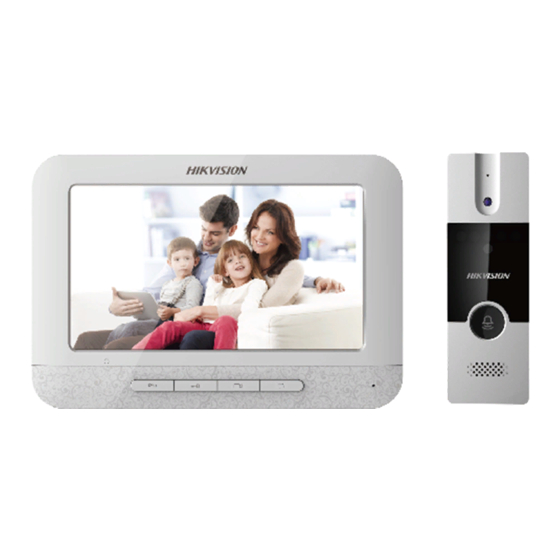
Video Door Phone·User Manual 2 Appearance Description 2.1 Indoor Station Table 2-1 Components Description Description LCD Display Screen Power Supply Indicator Call Accept/Decline Key Unlock Key Live View Key Image Key Volume Wheel Microphone Terminals and Interfaces Loudspeaker Figure 2-1 Indoor Station Appearance 2.2 Door Station Table 2-2 Components Description Description... -
Page 9: Terminals And Wirings
Video Door Phone·User Manual 3 Terminals and Wirings 3.1 Terminals and Interfaces Figure 3-1 Terminals of Indoor Station Figure 3-2 Terminals of Door Station Table 3-1 Descriptions of Terminals and Interfaces (Indoor Station) Name Interface Description Camera Analog Camera Access Power Supply 12 VDC 12 VDC Power Supply Input... -
Page 10: Wiring Description
Video Door Phone·User Manual 3.2 Wiring Description Purpose: A four-wire video intercom system is mainly composed of the indoor station and the door station. You can connect the analog camera to the indoor station, and connect the electric bolt to the door station. Up to 2 door stations are supported simultaneously in the intercom system. -
Page 11: Wiring 2 (1 Door Station And 3 Indoor Stations)
Video Door Phone·User Manual Analog Camera Electric Bolt The electric bolt need an external power supply. Indoor Station B+ — Wire for power supply V — Wire for video input A — Wire for audio input/output Door Station G — Wire for grounding Figure 3-3 Wiring 1 (1 Door Station and 1 Indoor Station) 3.2.2 Wiring 2 (1 Door Station and 3 Indoor Stations) Electric Bolt... -
Page 12: Wiring 3 (2 Door Stations And 3 Indoor Stations)
Video Door Phone·User Manual 3.2.3 Wiring 3 (2 Door Stations and 3 Indoor Stations) Electric Electric Bolt 1 Bolt 2 Analog Camera 3 The electric bolt need an external power supply. Indoor Station 3 Analog Camera 2 Indoor Station 2 Analog Camera 1 Door Door... -
Page 13: Installation
Video Door Phone·User Manual 4 Installation Before you start: Make sure the device in the package is in good condition and all the assembly parts are included. The power supply the indoor station supports is 12 VDC. Please make sure your power supply matches your indoor station. -
Page 14: Door Station Installation
Video Door Phone·User Manual Figure 4-2 Installing the Plate 3. Hook the indoor station to the wall mounting plate tightly by inserting the plate hooks into the slots on the rear panel of the indoor station, during which the lock catch will be locked automatically. - Page 15 Video Door Phone·User Manual Wall Mounting Shield (Door Station) 48.83 mm 41.78 mm 7.6 mm 12±0.05 mm 28.02 mm Figure 4-4 Wall Mounting Shield Wall Mounting (Door Station) You can follow the following steps to install the door station. Steps: 1.
- Page 16 Video Door Phone·User Manual Wall Mounting Door Station Shield Panel Rear Panel Hooks Slots Figure 4-6 Hooking the Door Station to the Shield 3. Secure the door station with the mounting shield with the set screw. Set Screw Figure 4-7 Securing the Door Station...
-
Page 17: Local Operation
Video Door Phone·User Manual 5 Local Operation 5.1 Getting Started Before you start: Make sure all devices in the four-wire system have been well connected. The power supply the indoor station supports is 12 VDC. Please make sure your power supply matches your indoor station. -
Page 18: Live View
Video Door Phone·User Manual 5.4 Live View Connect the indoor station with door station and camera. You can get the live view of door station and analog camera in the indoor station. For one indoor station, up to 2 door stations and 1 camera can be connected to. Before you start: Make sure all devices in the four-wire system have been well connected. -
Page 19: Switch Language
Video Door Phone·User Manual When someone press the Call button on the door station to call the indoor station, press to capture the image. When you are answering the call from the door station, press to capture the image. - Page 20 Video Door Phone·User Manual UD11859B...
Need help?
Do you have a question about the DS-KIS204 and is the answer not in the manual?
Questions and answers