
Related Manuals for Acces I/O products USB-DIO-48


Summary of Contents for Acces I/O products USB-DIO-48
- Page 1 10623 Roselle Street, San Diego, CA 92121 • (858) 550-9559 • FAX (858) 550-7322 contactus@accesio.com • www.accesio.com MODEL USB-DIO-48 USB 48 CHANNEL DIGITAL INPUT/OUTPUT MODULE USER MANUAL FILE: MUSB-DIO-48.A1j...
- Page 2 ACCES, nor the rights of others. IBM PC, PC/XT, and PC/AT are registered trademarks of the International Business Machines Corporation. Printed in USA. Copyright 2009 by ACCES I/O Products Inc, 10623 Roselle Street, San Diego, CA 92121. All rights reserved.
- Page 3 Other than the above, no other warranty, expressed or implied, shall apply to any and all such equipment furnished or sold by ACCES. Manual USB-DIO-48...
-
Page 4: Table Of Contents
Chapter 4: USB Address Information................13 Chapter 5: Programming....................14 unsigned long DIO_Configure(DeviceIndex, bTristate, pOutMask, pData) ....14 unsigned long DIO_WriteAll(DeviceIndex,pData)............14 unsigned long DIO_ReadAll(DeviceIndex,Buffer) ............14 Chapter 6: Connector Pin Assignments .................15 Table 6-1: 50-Pin Connector Pin Assignments ............15 Chapter 7: Specifications....................16 Customer Comments......................17 Manual USB-DIO-48... -
Page 5: Chapter 1: Introduction
Laboratory Automation • Robotics • Machine Control • Security Systems, Energy Management • Relay Monitoring and Control • Parallel Data Transfer to PC • Sensing Switch Closures or TTL, DTL, CMOS Logic • Driving Indicator Lights or Recorders Manual USB-DIO-48... -
Page 6: Functional Description
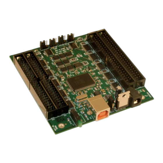
Power is supplied to the card via the USB cable or for higher current capabilities, external power may be used. Complimenting the high-retention USB type B connector (quickly recognized by the orange insulator) is a factory option for a high-retention external power screw terminal pair. Manual USB-DIO-48... -
Page 7: Ordering Guide
Figure 1-1: Block Diagram Ordering Guide USB-DIO-48 USB 48-channel digital input/output module Model Options • -OEM Board only version with no enclosure • Right angle headers (USB-DIO-48-OEM only) • -DIN DIN rail mounting bracket for integrating into existing DIN rail systems On-board DC power circuitry and external regulated AC/DC (5V) adapter Ext. -
Page 8: Included With Your Board
DIN rail One foot length of SNAP-TRACK with • DIN-SNAP four clips, for mounting up to two STB-50 screw terminal boards on a DIN rail DIN-rail mounting adapter plate for • MP104-DIN affixing any USB/104 module to a DIN-rail Manual USB-DIO-48... - Page 9 Figure 1-2: Enclosure Label Manual USB-DIO-48...
-
Page 10: Chapter 2: Installation
The board can be installed in any USB 2.0 or USB 1.1 port. Please refer to the USB I/O Quick Start Guide which can be found on the CD, for specific, quick steps to complete the hardware and software installation. Manual USB-DIO-48... -
Page 11: Chapter 3: Hardware Details
Diagram and the Option Selection Map when reading this section of the manual. There are two primary versions of this board, each has an option selection map. Figure 3-1: 48 Channel Board Option Selection Map Figure 3-2: 48 Channel OEM Board with Right Angle Headers Map Manual USB-DIO-48... -
Page 12: Usb Connector
10K resistor packs any un-used input will not have suppressed cross-talk. For pull-ups (most common), install these jumpers in the +5V position. For pull-downs, install these jumpers in the GND position. For neither, remove these jumpers. Manual USB-DIO-48... -
Page 13: Chapter 4: Usb Address Information
The VID is “0x1605" and the 48 bit board PID is “0x8002”. The Device Index is determined by how many of the devices you have in your system, and provides a unique identifier allowing you to access a specific board. Manual USB-DIO-48... -
Page 14: Chapter 5: Programming
*Buffer - pointer to the first element of an array of bytes. Each port will be read, and the reading stored in the corresponding byte in the array. Note that the size of "all" is the same as the size of the data given under DIO_Configure. Manual USB-DIO-48... -
Page 15: Chapter 6: Connector Pin Assignments
I/O 05 I/O 29 GROUND I/O 04 I/O 28 GROUND I/O 03 I/O 27 GROUND I/O 02 I/O 26 GROUND I/O 01 I/O 25 GROUND I/O 00 I/O 24 GROUND +5VDC +5VDC GROUND Table 6-1: 50-Pin Connector Pin Assignments Manual USB-DIO-48... -
Page 16: Chapter 7: Specifications
Operating Temperature: 0 °C. to 70 °C. • Storage Temperature: -40 °C. to +85 °C. • Humidity: 0 to 90% RH, non-condensing. • Board Dimension: 3.550 x 3.775 inches. • Box Dimension: 4.00 x 4.00" x 1.25 inches. Manual USB-DIO-48... -
Page 17: Customer Comments
If you experience any problems with this manual or just want to give us some feedback, please email us at: manuals@accesio.com. Please detail any errors you find, we will reply with manual updates 10623 Roselle Street, San Diego CA 92121 Tel. (858)550-9559 FAX (858)550-7322 www.accesio.com Manual USB-DIO-48...
Need help?
Do you have a question about the USB-DIO-48 and is the answer not in the manual?
Questions and answers