
Subscribe to Our Youtube Channel
Related Manuals for Amprobe PM55A


Summary of Contents for Amprobe PM55A
- Page 1 PM55A Automatic Precision Pocket Meter Users Manual • Mode d’emploi • Bedienungshandbuch • Manuale d’Uso • Manual de uso PN 2728864 July 2006 © 2006 Amprobe Test Tools. All rights reserved. Printed in Taiwan...
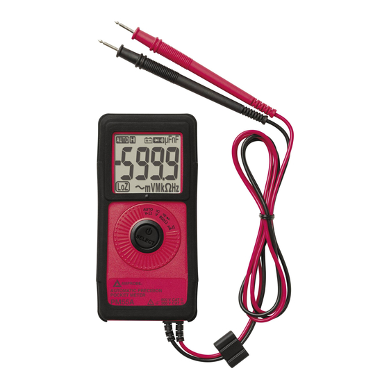
- Page 2 Press for 2 seconds to turn meter on. PM55A LCD display Rotary switch to select functions SELECT-button to select alternate functions and turn the power off and on. Permanently attached red test lead for positive (+) polarity and black test lead for ground...
-
Page 3: Table Of Contents
PM55A Pocket Meter Contents Introduction ......................2 Safety Information ....................2 Symbols Used in this Manual ................3 Turning the Meter On and Off ................3 Making Measurements ..................4 AutoTect Mode ....................4 Continuity, Audible With Symbolic Display ............5 Electric Field EF-Detection, VolTect ..............5 Voltage......................7... -
Page 4: Introduction
This unique meter has a full complement of features in a package only 3/8 inch thick, weighing less than 3 oz. for the utmost in shirt-pocket portability. The PM55A is fully autoranging and has an oversized, easy-to-read digital display. With an AutoTect™ feature that enables the meter to detect and display measurements of AC Volts, DC Volts and Resistance. -
Page 5: Symbols Used In This Manual
• Exercise extreme caution when: measuring voltage >20 V // current >10 mA // AC power line with inductive loads // AC power line during electrical storms // current, when the fuse blows in a circuit with open circuit voltage > 600 V // servicing CRT equipment. •... -
Page 6: Making Measurements
Making Measurements All measurements described in this manual use the Red test lead for positive (+) polarity and Black test lead for Ground reference (-) unless otherwise specified AutoTect mode is the default function in Auto V-Ω position. Press the SELECT button momentarily to select and step through the functions: •... -
Page 7: Continuity, Audible With Symbolic Display
AutoTect Mode This AutoTect feature automatically selects measurement function of V dc, V ac, or resistance based on the input via the test leads. ● With no input, the meter displays Auto when it is ready. ● With no voltage signal but a resistance below 6 MΩ is present, the meter displays the resistance value. - Page 8 • For more precise indication of live wires, such as distinguishing between live and ground sockets, use or V ac manual function selection for direct contact voltage measurements. Note For Maximum sensitivity, hold the meter away from the VolTect corner.
-
Page 9: Voltage
Voltage With Auto on the LCD, press the SELECT button 3 times to select V ac function. The meter displays LoZBV when it is ready.This function is auto-ranging. With Auto on the LCD, press the SELECT button 4 times to select V dc. The meter displays LoZ V when it is ready. -
Page 10: 600 Ω
600 Ω Press the SELECT button to select the lowest 600 Ω range for lower resistance measurements. It is an extended range to complement the AutoTect resistance function. µA dc and µA ac Turn the rotary switch to the µA position, µA dc is the default function. There is no annunciator for dc. -
Page 11: Repair
Resellers are not authorized to extend any other warranty on Amprobe ’s behalf. To obtain service during the warranty period, return the product with proof of purchase to an authorized Amprobe Test Tools Service Center or to a Amprobe dealer or distributor. - Page 12 Test Tools Service Center (see below for address). Non-Warranty Repairs and Replacement – US and Canada Non-warranty repairs in the United States and Canada should be sent to a Amprobe Test Tools Service Center. Call Amprobe Test Tools or inquire at your point of purchase for current repair and ...
-
Page 13: Specifications
Specifications General Specifications Display and Update Rate: 3-5/6 digits 6000 counts; Updates 5 per second nominal Operating Temperature: 0 °C - 40 °C Relative Humidity: Maximum 80% R.H. up to 31 °C, decreasing linearly to 50% R.H. at 40 °C Altitude: Operating below 2000 m Storage Temperature: -20 °C ~ 60 °C, <... - Page 14 precautions to avoid misleading results when making measurements in the presence of electronic interference. Accessories H-PM protective holster, VC3 soft carrying pouch, battery installed, and User’s manual Electrical Specifications (Accuracy @ 23 °C ± 5 °C and < 75% R.H.) RF Field @ 3 V/m: Specified accuracy + 45 d (Capacitance not specified) DC Voltage Range...
- Page 15 Capacitance Range Accuracy ±(3.5%+6 dgt) 100.0nF, 1000nF, 10.00µF, 100.0µF Accuracy below 50nF is not specified Accuracies with film capacitor or better Updates > 1 minute on large values Specified with battery voltage above 2.8 V (half full battery). Accuracy decreases gradually to 12% at low battery warning voltage of approx.
- Page 16 DC µA Current Range Accuracy Burden Voltage 400.0 µA ±(1.5%+3 dgt) 6 mV/µA 2000 µA ±(1.2%+3 dgt) 6 mV/µA AC µA Current Range Accuracy Burden Voltage 400.0 µA ±(2.0%+3 dgt) 6 mV/µA 2000 µA ±(1.5%+3 dgt) 6 mV/µA Voltect Typical Voltage Bar Graph Indication 20 V to 80 V 45 V to 125 V...
Need help?
Do you have a question about the PM55A and is the answer not in the manual?
Questions and answers