Sign In
Upload
Download
Table of Contents
Contents
Add to my manuals
Delete from my manuals
Share
URL of this page:
HTML Link:
Bookmark this page
Add
Manual will be automatically added to "My Manuals"
Print this page
×
Bookmark added
×
Added to my manuals
Manuals
Brands
Amprobe Manuals
Measuring Instruments
AT-6000
User manual
Amprobe AT-6000 User Manual
Advanced wire tracer
Hide thumbs
1
2
Table Of Contents
3
4
5
6
7
8
9
10
11
12
13
14
15
16
17
18
19
20
21
22
23
24
25
26
27
28
29
30
31
32
33
page
of
33
Go
/
33
Contents
Table of Contents
Bookmarks
Table of Contents
Table of Contents
Precautions and Safety Measures
Kit Components
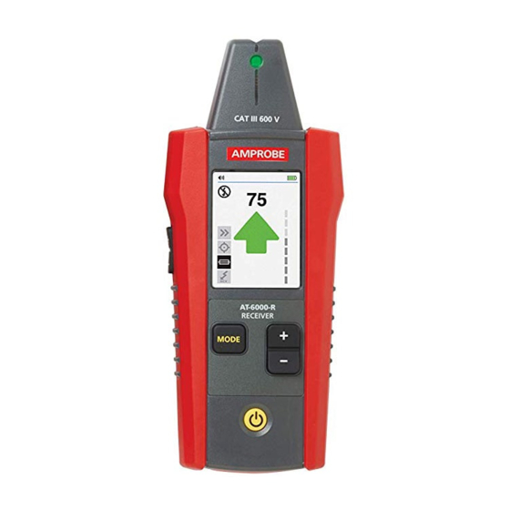
AT-6000-R Receiver
AT-6000-T Transmitter
CT-400 Signal Clamp (AT-6030 Kit)
Main Applications
Tracing Energized and De-Energized Wires
Identifying Breakers and Fuses (Energized and De-Energized)
Non-Contact Voltage Mode (NCV) and Passive Tracing
Special Applications
GFCI-Protected Circuit Wire Tracing
Finding Breaks/Opens
Finding Shorts
Tracing Wires in Metal Conduit
Tracing Non-Metallic Pipes and Conduits
Tracing Shielded Wires
Tracing Underground Wires
Tracing Low Voltage Wires and Data Cables
Sorting Bundled Wires
Mapping a Circuit Using Test Leads Connection
Tracing Breakers on Systems with Light Dimmers
Signal Clamp - Closed Loop Circuits
Signal Clamp - Mapping Circuits
Maintenance
Battery Replacement
Fuse Replacement
Specifications
Advertisement
Quick Links
Download this manual
1.800.544.2843
AT-6000
Advanced Wire Tracer
AT-6020
AT-6030
User Manual
8/2017, 6009478 Rev B
©2017 Amprobe Test Tools.
All rights reserved. Printed in China.
www.calcert.com
15
10
20
5
25
0
30
sales@calcert.com
Table of
Contents
Previous
Page
Next
Page
1
2
3
4
5
Advertisement
Table of Contents
Need help?
Do you have a question about the AT-6000 and is the answer not in the manual?
Ask a question
Questions and answers
Related Manuals for Amprobe AT-6000
GPS Amprobe AT-6020 User Manual
At-6000 series, advanced wire tracers (104 pages)
Measuring Instruments Amprobe AT-2000-A Series Quick Manual
Advanced wire tracer (2 pages)
Measuring Instruments Amprobe AT-3500 User Manual
Underground cable/pipe locator system (16 pages)
Measuring Instruments Amprobe AT-7020 User Manual
Advanced wire tracers (146 pages)
Measuring Instruments Amprobe AT-6000-R Quick Start Manual
At-6000 series. advanced wire tracer (10 pages)
Measuring Instruments Amprobe AT-6000-T Quick Start Manual
At-6000 series. advanced wire tracer (10 pages)
Measuring Instruments Amprobe AT-6020 KIT User Manual
Advanced wire tracer (33 pages)
Measuring Instruments Amprobe AT-6030 KIT User Manual
Advanced wire tracer (33 pages)
Measuring Instruments Amprobe ACDC-100 User Manual
Versatile ac/dc clamp-on multimeter series (16 pages)
Measuring Instruments Amprobe AM-530 User Manual
Hvac mulitmeter/true-rms electrical contractor multimeter (75 pages)
Measuring Instruments Amprobe AM-500 Replacement Instructions Manual
(40 pages)
Measuring Instruments Amprobe AD40B User Manual
Mini clamp meters (36 pages)
Measuring Instruments Amprobe AMP-25 Mini-Clamp User Manual
(55 pages)
Measuring Instruments Amprobe MEGATEST 5000 Owner's Manual
5000 v megohmmeter (32 pages)
Measuring Instruments Amprobe ACD-20SW User Manual
Digital clamp meter (84 pages)
Measuring Instruments Amprobe ACD-16 Pro User Manual
(17 pages)
This manual is also suitable for:
At-6020
At-6030
At-6020 kit
At-6030 kit
095969842723
095969842730
Table of Contents
Print
Rename the bookmark
Delete bookmark?
Delete from my manuals?
Login
Sign In
OR
Sign in with Facebook
Sign in with Google
Upload manual
Upload from disk
Upload from URL


Need help?
Do you have a question about the AT-6000 and is the answer not in the manual?
Questions and answers