Sign In
Upload
Download
Table of Contents
Contents
Add to my manuals
Delete from my manuals
Share
URL of this page:
HTML Link:
Bookmark this page
Add
Manual will be automatically added to "My Manuals"
Print this page
×
Bookmark added
×
Added to my manuals
Manuals
Brands
Amprobe Manuals
Measuring Instruments
ACD - 50NAV
User manual
Amprobe ACD - 50NAV User Manual
600a ac navigator clamp; 600a ac trms navigator clamp; 600a ac/dc trms navigator clamp; 1000a ac trms navigator clamp; 1000a ac/dc trms navigator clamp
Hide thumbs
1
2
3
4
5
Table Of Contents
6
7
8
9
10
11
12
13
14
15
16
17
18
19
20
21
22
23
24
25
26
27
28
29
30
31
32
33
34
35
36
page
of
36
Go
/
36
Contents
Table of Contents
Troubleshooting
Bookmarks
Table of Contents
Table of Contents
Symbols
Unpacking and Inspection
Features
Operation
Making Basic Measurement
Measuring Voltage
Measuring Current
Auto Sense Mode
Peak Hold
Inrush Current
DC a Zero
Measuring Frequency
Max/Min/Avg
THD Measurement
Lpf
Measuring Active Power (W) / Power Factor (PF)
Phase Rotation
OHM Measurements
Measuring Capacitance
Measuring Temperature °C / °F
Measuring Μa Current
AUTO/MANUAL Range
HOLD Key
Voltsense
Buzzer
Power-Up Option
Battery State Display
Specification
Maintenance and Repair
Trouble Shooting
Cleaning and Storage
Battery Replacement
Advertisement
Quick Links
1
Making Basic Measurement
2
Inrush Current
3
Thd Measurement
4
Measuring Active Power (W) / Power Factor (Pf)
5
Phase Rotation
6
Specification
Download this manual
Users Manual
• Mode d'emploi
• Bedienungshandbuch
• Manual d'Uso
• Manual de uso
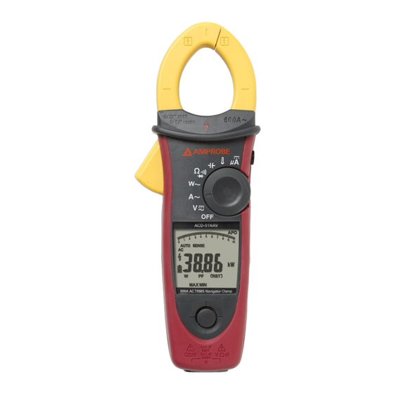
ACD-50NAV
600A AC Navigator Clamp
ACD-51NAV
600A AC TRMS
Navigator Clamp
ACDC-52NAV
600A AC / DC TRMS
Navigator Clamp
ACD-53NAV
1000A AC TRMS
Navigator Clamp
ACDC-54NAV
1000A AC / DC TRMS
Navigator Clamp
1
Table of
Contents
Previous
Page
Next
Page
1
2
3
4
5
Advertisement
Table of Contents
Need help?
Do you have a question about the ACD - 50NAV and is the answer not in the manual?
Ask a question
Questions and answers
Related Manuals for Amprobe ACD - 50NAV
Measuring Instruments Amprobe ACD - 51NAV User Manual
600a ac navigator clamp; 600a ac trms navigator clamp; 600a ac/dc trms navigator clamp; 1000a ac trms navigator clamp; 1000a ac/dc trms navigator clamp (36 pages)
Measuring Instruments Amprobe ACD - 53NAV User Manual
600a ac navigator clamp; 600a ac trms navigator clamp; 600a ac/dc trms navigator clamp; 1000a ac trms navigator clamp; 1000a ac/dc trms navigator clamp (36 pages)
Measuring Instruments Amprobe ACD-51HP User Manual
(71 pages)
Measuring Instruments Amprobe ACDC-100 User Manual
Versatile ac/dc clamp-on multimeter series (16 pages)
Measuring Instruments Amprobe ACD-3300 IND User Manual
Cat iv industrial true rms clamp meters (98 pages)
Measuring Instruments Amprobe ACD-3300 IND User Manual
Cat iv industrial true rms clamp meters (17 pages)
Measuring Instruments Amprobe ACD-31P User Manual
1000a clamp-on power quality meters (121 pages)
Measuring Instruments Amprobe ACD-6 PRO User Manual
Professional 1000a clamp meters (17 pages)
Measuring Instruments Amprobe ACD-45PQ User Manual
600a power quality clamp (29 pages)
Measuring Instruments Amprobe ACD-15 Pro User Manual
Clamp-on multimeter series (20 pages)
Measuring Instruments Amprobe ACD-21SW User Manual
Digital clamp meter (17 pages)
Measuring Instruments Amprobe ACD-20SW User Manual
Digital clamp meter (84 pages)
Measuring Instruments Amprobe ACD-20SW User Manual
Digital clamp meter (17 pages)
Measuring Instruments Amprobe ACD-16 Pro User Manual
(17 pages)
Measuring Instruments Amprobe ACD-23SW User Manual
Digital clamp meter (20 pages)
Measuring Instruments Amprobe ACD-10 PRO Instruction Manual
(17 pages)
This manual is also suitable for:
Acd - 51nav
Acdc - 52nav
Acd - 53nav
Acdc - 54nav
Table of Contents
Print
Rename the bookmark
Delete bookmark?
Delete from my manuals?
Login
Sign In
OR
Sign in with Facebook
Sign in with Google
Upload manual
Upload from disk
Upload from URL


Need help?
Do you have a question about the ACD - 50NAV and is the answer not in the manual?
Questions and answers