
Related Manuals for Furuno PG500R


Summary of Contents for Furuno PG500R
- Page 1 OPERATOR'S MANUAL INTEGRATED HEADING SENSOR PG-500 FLUXGATE HEADING SENSOR C-500 Model www.furuno.com...
- Page 2 How to discard a used battery Some FURUNO products have a battery(ies). To see if your product has a battery, see the chapter on Maintenance. If a battery is used, tape the + and - terminals of the battery before disposal to prevent fire, heat generation caused by short circuit.
- Page 3 SAFETY INSTRUCTIONS Safety Information for the Installer WARNING CAUTION Turn off the power at the mains Confirm that the power supply voltage switchboard before beginning the is compatible with the voltage rating installation. of the equipment. Post a sign near the switch to indicate it should not be turned on while the Connection to the wrong power supply can cause fire or damage the equipment.
-
Page 4: Table Of Contents
TABLE OF CONTENTS FOREWORD ......................iv SYSTEM CONFIGURATION ................. v EQUIPMENT LIST....................vi 1. OPERATION ...................... 1 Controls and Indications ...................... 1 Turning the Power On/Off ....................1 Automatic Distortion Compensation ..................3 Damping Control ........................3 Selecting Output Data Format ....................4 MAINTENANCE &... -
Page 5: Foreword
A Word to PG-500/C-500 Owners Congratulations on your choice of the FURUNO PG-500 Integrated Heading Sensor, C-500 Fluxgate Heading Sensor. We are confident you will see why the FURUNO name has become synonymous with quality and reliability. Since 1948, FURUNO Electric Company has enjoyed an enviable reputation for innovative and dependable marine electronics equipment. -
Page 6: System Configuration
SYSTEM CONFIGURATION Standard connection PG-500/C-500 NMEA EXTERNAL EQUIPMENT Format (NAVnet series, etc.) AD-10 Format RADAR/ARPA (MODEL1832, 1721Mk-2, etc.) 12-24 VDC NMEA Format EXTERNAL EQUIPMENT (NAVnet series, etc.) Connection with NAVpilot-500 PG-500 Power, AD-10 Format operation command (Magnetic heading) NAVpilot-500 Processor unit RADAR/ARPA NMEA Format (MODEL1832, 1721Mk-2, etc.) -
Page 7: Equipment List
EQUIPMENT LIST Standard set Name Type Remarks PG-500-E Fluxgate and rate sensor Sensor C-500-E Fluxgate sensor Installation Materials 1 set Refer to the packing list (page A-1). 1 set Fuse Spare Parts Refer to the packing list (page A-1). Option Name Type Code No. -
Page 8: Operation
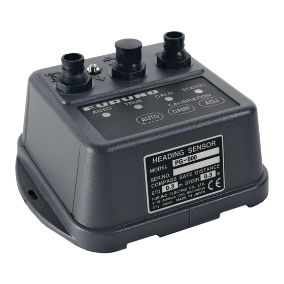
1. OPERATION Controls and Indications Program version The program version, denoted by the LEDs On: Auto correction is on. in binary notation, is shown. For example, Off: Auto correction is off. the LED state shown on the next page On: True heading is output. means the program version is “1.03”. - Page 9 1. OPERATION Sequence of Start up test LED Sequence Test name AUTO TRUE CALB STATUS 0.5 seconds Program Version No. AUTO TRUE CALB STATUS 0.5 seconds AUTO TRUE CALB STATUS All LEDs go off. 0.5 seconds AUTO TRUE CALB STATUS ROM, RAM check 0.5 seconds AUTO...
-
Page 10: Automatic Distortion Compensation
1. OPERATION Automatic Distortion Damping Control Compensation The damping control determines how sensitively the sensor responds to change of Magnetic field distortion on your vessel has ship’s heading. When the damping value is been compensated at the installation. When large, the sensor responds smoothly but a the magnetic field distortion changes, it can small boat may wander after the turning. -
Page 11: Selecting Output Data Format
To output true heading, do the following: variation as shown in 3.4 Heading Alignment on page 11. HDM 1. Connect Furuno GPS Navigator which sentence, however, cannot be can output data sentence RMC or VTG. changed to true heading. For HDG 2. -
Page 12: Maintenance & Troubleshooting
2. MAINTENANCE & TROUBLESHOOTING Maintenance Regular maintenance is important to maintain intended performance over a long period. Regularly check the following: • Clean the component with a soft cloth. Do not use chemical cleaners; they can remove paint and markings. •... -
Page 13: Diagnostic Test
2. MAINTENANCE & TROUBLESHOOTING Diagnostic Test AUTO TRUE CALB STATUS This equipment has a diagnostic test which Start checks the LED, key operation, ROM, RAM, AUTO LED EEPROM, magnetic sensor, rate sensor : OK (PG-500 only) and loop back for proper TRUE LED operation. -
Page 14: Error Status
2. MAINTENANCE & TROUBLESHOOTING 2.4 Error Status When error is detected, all LEDs go off and then the STATUS LED blinks or goes off depending on error type as shown in the table below. LED status Meaning Remarks STATUS LED Magnetic blinks slowly. -
Page 15: Installation
3. INSTALLATION Mounting Ship's bow This sensor must be mounted indoors on the Bow mark horizontal plane. When selecting a mounting location, keep in mind the following points: • Vibration at the mounting location should be minimal. Fixing hole • Install the sensor as far as possible from 4.5 mm) power cables and ferrous materials. -
Page 16: Connections
3. INSTALLATION Connections Grounding Ground the equipment as follows to prevent Connect cables as shown below. loss of sensitivity: Leave sufficient slack in cables for • maintenance and checking ease. If cables The ground wire should be as short as run outside the bridge, run them through possible. -
Page 17: Correcting Magnetic Field Distortion
3. INSTALLATION Correcting Magnetic light. Wait 30 seconds for the sensor to return to normal operation, or press any Field Distortion key for quick return. The magnetic field around the sensor is subject to change with the ship structure, AUTO TRUE CALB STATUS... -
Page 18: Heading Alignment
3. INSTALLATION Heading Alignment AUTO STATUS TRUE CALB Heading alignment is required when sensor +1° heading is different from actual heading. This alignment must be done using magnetic +2° heading (default setting). +3° +4° CAUTION +5° Turn off the autopilot before aligning +6°... -
Page 19: Setting Output Data
3. INSTALLATION Setting Output Data AUTO TRUE CALB STATUS Setting output interval (sentence) The default setting is 200 ms. :On (current setting) :Off Refer to the table shown on the next page for proper setting. : True heading : Magnetic heading : Magnetic heading &... -
Page 20: Setting Baud Rate
3. INSTALLATION Setting Baud Rate Relation baud rate and output interval Baud rate Output interval Available sentences Set the baud rate of external equipment. No output The default setting is 4800 bps. Up to two sentences can be output. When connecting with the NAVpilot-500, use 4800 the default setting (4800 bps). -
Page 21: Specifications
30°/s rate-of turn 1.4 I/O Port Input: 1 port Output: 2 ports (one port drives 3 outputs) 1.5 Interface Output FURUNO AD-10 format IEC 61162-1 (NMEA 0183 Ver2.0) HDG, HDT, HDM Input IEC 61162-1 (NMEA 0183 Ver1.5/2.0) RMC, VTG 1.6 Data Update... -
Page 22: Packing List
A C K I N G L I S T 64AV-X-9851 -5 PG-500/C-500 N A M E DESCRIPTION/CODE № O U T L I N E Q'TY ユニット UNIT ハイブリッドヘディングセンサー PG-500 INTEGRATED HEADING SENSOR (*1) 000-040-467-00 ヘディング゙センサー C-500 FLUXGATE HEADING SENSOR (*1) 000-040-468-00 予備品... -
Page 24: Interconnecion Diagram
ヘディングセンサー HEADING SENSOR PG‑500/C‑500 オートパイロット レーダー AD10 MJ‑A6SPFD MJ‑A6SPF0007,10m,φ6 MJ‑A6SPFD 潮流計 AD10̲DATA̲H シロ DATA̲H AD10̲DATA̲C クロ DATA̲C AUTOPILOT キ AD10̲CLK̲H CLK̲H RADAR AD10̲CLK̲C ミドリ CLK̲C CURRENT INDICATOR NAVnet シリーズ NMEA NAVnet series MJ‑A6SPF0003,5m,φ6 MJ‑A6SPFD IEC61162 シロ TD̲A NMEA0183 OUT 航法装置 TD̲B クロ... - Page 25 When a claim is made, FURUNO has a right to choose whether with other electronic devices. The imported product may also be to repair the product or replace it.
- Page 26 24 months from installation date provided the work is done by Furuno U.S.A., Inc. or an AUTHORIZED Furuno dealer during normal shop hours and within a radius of 50 miles of the shop location.
- Page 28 The paper used in this manual is elemental chlorine free. ・FURUNO Authorized Distributor/Dealer 9-52 Ashihara-cho, Nishinomiya, 662-8580, JAPAN A : APR 2003 Printed in Japan All rights reserved. D4 : NOV . 16, 2021 Pub. No. OME-72550-D4 (YOTA ) PG-500/C-500...
Need help?
Do you have a question about the PG500R and is the answer not in the manual?
Questions and answers