Table of Contents

Advertisement

Quick Links

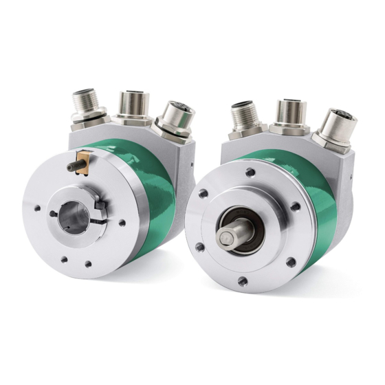
Smart encoders & actuators
EM58 PL/PLA
HS58 PL/PLA
HM58 PL/PLA
• EM58 27-bit multiturn encoder for standard purposes
• HS58 18-bit singleturn encoder for high precision demands
• HM58 30-bit multiturn encoder for high end applications
• DS301 and DS406 profile compliance (CANopen over Ethernet)
• Real-Time Ethernet (RTE) and deterministic communication
Suitable for the following models:
EM58, EM58S PL/PLA
EMC58, EMC59, EMC60 PL/PLA
HS58, HS58S PL/PLA
HSC58, HSC59, HSC60 PL/PLA
HM58, HM58S PL/PLA
HMC58, HMC59, HMC60 PL/PLA
Lika Electronic

User's guide

Tel. +39 0445 806600
General Contents
Safety summary
Identification
Mounting instructions
Electrical connections
Quick reference
POWERLINK interface
Default parameters list
info@lika.biz
21
23
24
29
36
61
104
www.lika.biz

Advertisement

Table of Contents
loading
Need help?

Need help?

Do you have a question about the POWERLINK EM58 PL and is the answer not in the manual?

Questions and answers

Summary of Contents for Lika POWERLINK EM58 PL

  • Page 1: User's Guide

    Mounting instructions HS58, HS58S PL/PLA • Electrical connections HSC58, HSC59, HSC60 PL/PLA • Quick reference HM58, HM58S PL/PLA • POWERLINK interface HMC58, HMC59, HMC60 PL/PLA • Default parameters list Lika Electronic • Tel. +39 0445 806600 • info@lika.biz • www.lika.biz...
  • Page 2 Tous droits réservés. This document and information contained herein are the property of Lika Electronic s.r.l. and shall not be reproduced in whole or in part without prior written approval of Lika Electronic s.r.l. Translation, reproduction and total or partial modification (photostat copies, film and microfilm included and any other means) are forbidden without written authorisation of Lika Electronic s.r.l.
  • Page 3: Table Of Contents

    General contents User's guide......................................1 General contents.....................................3 Subject index.....................................7 Typographic and iconographic conventions........................10 Preliminary information................................11 Glossary of POWERLINK terms.............................12 List of abbreviations...................................18 References......................................20 1 Safety summary..................................21 1.1 Safety......................................21 1.2 Electrical safety..................................21 1.3 Mechanical safety................................22 2 Identification....................................23 3 Mounting instructions................................24 3.1 Solid shaft encoders................................24 3.1.1.
  • Page 4 5.4.8 Setting the cycle time...............................51 5.4.9 Preset setting program.............................52 5.4.10 Parameters storing program..........................55 5.4.11 Default parameters restoring program......................56 5.4.12 Entering the System Diagnostics Manager (SDM)..................57 5.4.13 Logger Monitor................................60 6 POWERLINK interface................................61 6.1 Overview....................................61 6.2 Physical layer..................................62 6.3 Reference model..................................62 6.4 CANopen over Ethernet..............................63 6.5 POWERLINK nodes................................63 6.5.1 POWERLINK Managing Node (MN)........................63 6.5.2 POWERLINK Controlled Node CN)........................63...
  • Page 5 1018-04 NMT_IdentityObject_REC.SerialNo_U32..................76 1020-00 CFM_VerifyConfiguration_REC......................76 1020-01 CFM_VerifyConfiguration_REC.ConfDate_U32...............76 1020-02 CFM_VerifyConfiguration_REC.ConfTime_U32...............76 1030-00 NMT_InterfaceGroup_0h_REC......................76 1030-01 NMT_InterfaceGroup_0h_REC.InterfaceIndex_U16.............76 1030-02 NMT_InterfaceGroup_0h_REC.InterfaceDescription_VSTR..........77 1030-03 NMT_InterfaceGroup_0h_REC.InterfaceType_U8..............77 1030-04 NMT_InterfaceGroup_0h_REC.InterfaceMtu_U16..............77 1030-05 NMT_InterfaceGroup_0h_REC.InterfacePhysAddress_OSTR...........77 1030-06 NMT_InterfaceGroup_0h_REC.InterfaceName_VSTR............77 1030-07 NMT_InterfaceGroup_0h_REC.InterfaceOperState_U8............77 1030-08 NMT_InterfaceGroup_0h_REC.InterfaceAdminState_U8..........78 1030-09 NMT_InterfaceGroup_0h_REC.Valid_BOOL................78 1300 SDO_SequLayerTimeout_U32........................78 1800-00 PDO_TxCommParam_00h_REC......................78 1800-01 PDO_TxCommParam_00h_REC.NodeID_U8................78 1800-02 PDO_TxCommParam_00h_REC.MappingVersion_U8............78 1A00-00 PDO_TxMappParam_00h_AU64.......................79 1A00-01 PDO_TxMappParam_00h_AU64.ObjectMapping..............79 1A00-02 PDO_TxMappParam_00h_AU64.ObjectMapping..............79 1C0B-00...
  • Page 6 1F99 NMT_CNBasicEthernetTimeout_U32......................88 1F9B-00 NMT_MultiplCycleAssign_AU8......................89 1F9B-01 NMT_MultiplCycleAssign_AU8.CycleNo..................89 1F9E NMT_ResetCmd_U8............................89 6.12.2 Manufacturer Specific Profile Area objects....................90 2002 Speed format................................90 6.12.3 Standardised Device Profile Area objects (DS 406)...................91 6000 Operating parameters.............................91 Code sequence................................91 Scaling function................................91 Restore default parameters..........................92 Store parameters................................92 6001 Measuring units per revolution........................93 6002 Total measuring range in measuring units..................94...
  • Page 7: Subject Index

    Subject index 1030-08 NMT_InterfaceGroup_0h_REC.InterfaceAdmin 1000 NMT_DeviceType_U32........74 State_U8.................78 1001 ERR_ErrorRegister_U8........74 1030-09 1006 NMT_CycleLen_U32..........74 NMT_InterfaceGroup_0h_REC.Valid_BOOL..78 1008 NMT_ManufactDevName_VS......74 1300 SDO_SequLayerTimeout_U32......78 1009 NMT_ManufactHwVers_VS......75 1800-00 PDO_TxCommParam_00h_REC....78 100A NMT_ManufactSwVers_VS......75 1800-01 1018-00 NMT_IdentityObject_REC......75 PDO_TxCommParam_00h_REC.NodeID_U8...78 1018-01 1800-02 NMT_IdentityObject_REC.VendorID_U32..75 PDO_TxCommParam_00h_REC.MappingVersio 1018-02 n_U8.................78 NMT_IdentityObject_REC.ProductCode_U32. 75 1A00-00 PDO_TxMappParam_00h_AU64....79 1018-03 1A00-01 NMT_IdentityObject_REC.RevisionNo_U32..75 PDO_TxMappParam_00h_AU64.ObjectMappin 1018-04 NMT_IdentityObject_REC.SerialNo_U32 g..................79...
  • Page 8 1F93-02 Alarms...................99 NMT_EPLNodeID_REC.NodeIDByHW_BOOL..86 1F98-00 NMT_CycleTiming_REC.......86 CFM_VerifyConfiguration_REC........76 1F98-01 CFM_VerifyConfiguration_REC.ConfDate_U32..76 NMT_CycleTiming_REC.IsochrTxMaxPayload_U CFM_VerifyConfiguration_REC.ConfTime_U32..76 16..................86 Code sequence............91, 98 1F98-02 NMT_CycleTiming_REC.IsochrRxMaxPayload_U DLL_CNCRCError_REC...........80 16..................87 DLL_CNCRCError_REC.CumulativeCnt_U32..81 1F98-03 DLL_CNCRCError_REC.Threshold_U32....81 NMT_CycleTiming_REC.PresMaxLatency_U32 DLL_CNCRCError_REC.ThresholdCnt_U32....81 .....................87 DLL_CNLossOfSocTolerance_U32......81 1F98-04 DLL_CNLossSoC_REC............80 NMT_CycleTiming_REC.PreqActPayloadLimit_U DLL_CNLossSoC_REC.CumulativeCnt_U32..80 16..................87 DLL_CNLossSoC_REC.Threshold_U32.....80 1F98-05 DLL_CNLossSoC_REC.ThresholdCnt_U32....80 NMT_CycleTiming_REC.PresActPayloadLimit_U 16..................87 ERR_ErrorRegister_U8...........74 1F98-06 NMT_CycleTiming_REC.AsndMaxLatency_U32 Flash memory error............100 .....................88 1F98-07 Machine data not valid..........99...
  • Page 9 NMT_EPLVersion_U8............84 NMT_PResPayloadLimitList_AU16.PResPayloadLi NMT_FeatureFlags_U32..........83 mit..................86 NMT_IdentityObject_REC..........75 NMT_ResetCmd_U8............89 NMT_IdentityObject_REC.ProductCode_U32..75 Number of revolutions..........99 NMT_IdentityObject_REC.RevisionNo_U32..75 NMT_IdentityObject_REC.SerialNo_U32....76 Offset value..............101 NMT_IdentityObject_REC.VendorID_U32.....75 Operating parameters............91 NMT_InterfaceGroup_0h_REC........76 Operating status...............98 NMT_InterfaceGroup_0h_REC.InterfaceAdminSta Operating time...............101 te_U8................78 NMT_InterfaceGroup_0h_REC.InterfaceDescripti PDO_TxCommParam_00h_REC.........78 on_VSTR................77 PDO_TxCommParam_00h_REC.MappingVersion_ NMT_InterfaceGroup_0h_REC.InterfaceIndex_U1 U8..................78 6..................76 PDO_TxCommParam_00h_REC.NodeID_U8..78 NMT_InterfaceGroup_0h_REC.InterfaceMtu_U16 PDO_TxMappParam_00h_AU64.......79 .....................77 PDO_TxMappParam_00h_AU64.ObjectMapping NMT_InterfaceGroup_0h_REC.InterfaceName_VS .....................79 TR..................77 Position value..............97 NMT_InterfaceGroup_0h_REC.InterfaceOperStat Preset value................96 e_U8..................77...
  • Page 10: Typographic And Iconographic Conventions

    Typographic and iconographic conventions In this guide, to make it easier to understand and read the text the following typographic and iconographic conventions are used: parameters and objects both of the device and the interface are coloured in GREEN; • alarms are coloured in RED;...
  • Page 11: Preliminary Information

    Preliminary information This guide is designed to provide the most complete information the operator needs to correctly and safely install and operate the following encoders equipped with POWERLINK interface: EMxxx13/16384PL-xx (multiturn encoder 13 + 14 bits) EMxxx13/16384PLA-xx HSxxx18/PL-xx (singleturn encoder 18 bits) HSxxx18/PLA-xx HMxxx16/16384PL-xx (multiturn encoder 16 + 14 bits)
  • Page 12: Glossary Of Powerlink Terms

    Glossary of POWERLINK terms POWERLINK, like many other networking systems, has a set of unique terminology. Table below contains a few of the technical terms used in this guide to describe the POWERLINK interface. They are listed in alphabetical order. Ageing Ageing is a common mechanism to maintain (cache) tables.
  • Page 13 Communication Profile”, so it is mandatory to read the DS301 profile before implementing the encoder profile. POWERLINK encoders from Lika Electronic comply with the “EPSG Draft Standard 301 Ethernet POWERLINK Communication Profile Specification Version 1.2.0”. See also “Profile”. Refer to page...
  • Page 14 IEEE 1588 This standard defines a protocol enabling synchronisation of clocks in distributed networked devices (e.g. connected via Ethernet). IP address The IP address is the name of the unit in a network using the Internet protocol. Refer to page 32. Isochronous Pertains to processes that require timing coordination to be successful.
  • Page 15 POWERLINK encoders from Lika Electronic comply with the “EPSG Draft Standard 301 Ethernet POWERLINK Communication Profile Specification Version 1.2.0”. See also “Encoder profile”. See on page 61.
  • Page 16 network that allows IP communication between a POWERLINK segment and any other datalink layer protocol carrying IP e.g. legacy Ethernet, POWERLINK etc. It is usually a separate network element acting as Controlled Node within the POWERLINK segment. Router Type 2 A Type 2 POWERLINK Router is a router between a POWERLINK segment and a CANopen network.
  • Page 17 Tree topology. • Refer to page 61. Transmission rate Data transfer rate (in bps). Refer to page 62.
  • Page 18: List Of Abbreviations

    List of abbreviations Table below contains a list of abbreviations (in alphabetical order) which may be used in this guide to describe the POWERLINK interface. Access Control List Address Resolution Protocol ASnd Asynchronous Send (POWERLINK frame type) Controller Area Network CAN in Automation POWERLINK Controlled Node Device Configuration File...
  • Page 19 PRes PollResponse (POWERLINK frame type) Prescaled Slot (flag in POWERLINK frame) Precision Time Protocol Ready (flag in POWERLINK frame) Requests for Comments RPDO Receive Process Data Object Request to Send (flag in POWERLINK frame) SCNM Slot Communication Network Management Service Data Object SNMP Simple Network Management Protocol Start of Asynchronous (POWERLINK frame type)
  • Page 20: References

    References EPSG Draft Standard 301, Ethernet POWERLINK, Communication Profile Specification, Version 1.2.0 EPSG Draft Standard 311, Ethernet POWERLINK, XML Device Description, Version 1.0.0 CiA Draft Standard Proposal 301, Application layer and communication profile, Version 4.2.0 CiA Draft Standard 406, Device profile for encoders, Version 4.0.1 EPSG Draft Standard 302-A (EPSG DS 302-A), Ethernet POWERLINK, Part A: High Availability, Version 1.1.0 EPSG Draft Standard 302-B (EPSG DS 302-B), Ethernet POWERLINK, Part B: Multiple-ASnd,...
  • Page 21: Safety Summary

     failure to comply with these precautions or with specific warnings elsewhere in this manual violates safety standards of design, manufacture, and intended use of the equipment;  Lika Electronic assumes no liability for the customer's failure to comply with these requirements. 1.2 Electrical safety ...
  • Page 22: Mechanical Safety

    EM58 • HS58 • HM58 POWERLINK 1.3 Mechanical safety  Install the device following strictly the information in the “3 -Mounting instructions” section on page 24;  mechanical installation has to be carried out with stationary mechanical parts;  do not disassemble the encoder; ...
  • Page 23: Identification

    MAC address printed on the label applied to its body. Information is listed in the delivery document too. Please always quote the order code, the serial number and the MAC address when reaching Lika Electronic for purchasing spare parts or needing assistance. For any information on the technical characteristics of the product refer to the technical catalogue.
  • Page 24: Mounting Instructions

    EM58 • HS58 • HM58 POWERLINK Mounting instructions WARNING Installation and maintenance operations have to be carried out by qualified personnel only, with power supply disconnected and mechanical parts absolutely in stop. For any information on the mechanical data and the electrical characteristics of the encoder please refer to the technical catalogue.
  • Page 25: Installation Using Fixing Clamps (Code Lkm-386)

    EM58 • HS58 • HM58 POWERLINK 3.1.2 Installation using fixing clamps (code LKM-386) a [mm] b [mm] c [mm] d [mm] EM58, HS58, HM58 50 F7 EM58S, HS58S, HM58S 36 H7 3.1.3 Installation using a mounting bell (code PF4256) NOTE In order to guarantee reliability over time of the encoder mechanical parts, we recommend a flexible coupling to be installed between the encoder and the motor shaft.
  • Page 26: Hollow Shaft Encoders

    • insert the anti-rotation pin 1 into the slot on the flange of the encoder; this secures it in place by grub screw 2, preset at Lika; • fix the collar 3 to the encoder shaft (apply some threadlocker to the screw 3).
  • Page 27: Emc59, Hsc59, Hmc59

    EM58 • HS58 • HM58 POWERLINK 3.2.2 EMC59, HSC59, HMC59 • Mount the encoder on the motor shaft using the reducing sleeve 8 (if supplied). Avoid forcing the encoder shaft; • fasten the fixing plate 4 to the rear of the motor using two M3 x 8 cylindrical head screws 5;...
  • Page 28: Emc60, Hsc60, Hmc60

    EM58 • HS58 • HM58 POWERLINK 3.2.3 EMC60, HSC60, HMC60 • Fix the tempered pin 6 to the rear of the motor; • mount the encoder on the motor shaft using the reducing sleeve 8 (if supplied). Avoid forcing the encoder shaft; •...
  • Page 29: Electrical Connections

    EM58 • HS58 • HM58 POWERLINK Electrical connections WARNING Power supply must be turned off before performing any electrical connection! 4.1 Connection cap WARNING Do not remove or mount the connection cap with power supply switched ON. Damage may be caused to internal components. The DIP switch meant to set the encoder node ID is located inside the connection cap.
  • Page 30: Pwr Power Supply Connector (Figure 2)

    EM58 • HS58 • HM58 POWERLINK Figure 2 - Connectors and diagnostic LEDs 4.2 PWR Power supply connector (Figure 2) M12 4-pin male connector with A coding is used for power supply. Description +10Vdc +30Vdc n.c. 0Vdc n.c. n.c. = not connected 4.3 P1 Port 1 and P2 Port 2 connectors (Figure 2) Two M12 4-pin female connectors with D coding are used for Ethernet connection through port 1 and port 2.
  • Page 31: Network Configuration: Cables, Hubs, Switches - Recommendations

    Lika's EC- pre-assembled cables are fitted with shield connection to the connector ring nut in order to allow grounding through the body of the device. Lika's E- connectors have a plastic gland, thus grounding is not possible. If metal connectors are used, connect the cable shield properly as recommended by the manufacturer.
  • Page 32: Mac Address And Ip Address

    The private class C Net ID 192.168.100.0 is used in the POWERLINK network. A class C network provides 254 (1-254) IP addresses which match the number of valid POWERLINK Node IDs. As they are CNs, Lika encoders accept values from 1 to 239, in compliance with the POWERLINK specifications. Address 0 is invalid, addresses from 240 to 255 are reserved to MNs or special functions.
  • Page 33 EM58 • HS58 • HM58 POWERLINK The POWERLINK node ID is set via hardware using the DIP A DIP switch located inside the enclosure. To access the DIP A DIP switch please refer to the “4.1 Connection cap” section on page 29. Allowed node addresses range between 1 and 239.
  • Page 34: Diagnostic Leds (Figure 2)

    EM58 • HS58 • HM58 POWERLINK 4.9 Diagnostic LEDs (Figure 2) Five LEDs located in the cap of the encoder (see the Figure 2) are meant to show visually the operating or fault status of the encoder and the POWERLINK interface.
  • Page 35 EM58 • HS58 • HM58 POWERLINK If the NS Network State Error LED is also lit, a fatal error has occurred. Description PWR Power LED It shows the power supply state. (green) The encoder power supply is switched OFF. The encoder power supply is switched ON. Description NS Network It shows the current state of the network.
  • Page 36: Quick Reference

    EM58 • HS58 • HM58 POWERLINK Quick reference 5.1 Before starting Lika encoders are CN devices (Controlled Nodes e.g. Slaves: nodes without the ability to manage the SCNM mechanism, see on page 63) and comply with the “EPSG Draft Standard 301 Ethernet POWERLINK Communication Profile Specification Version 1.2.0”.
  • Page 37: Configuring The Encoder With Automation Studio V. 4.1 From B&R

    Lika Electronic POWERLINK encoder documentation is complete with an example project supplied free of charge. This program is designed to make your own project planning, programming, communication and diagnostics with the Automation Studio V.
  • Page 38: Encoder Installation Under Automation Studio Environment

    0000012E_Lika_HM16_16384_EthernetPOWERLINK.xdd: • intended for installation of HM58 series encoders. XDD files are paired with the Lika.bmp picture file available inside the file folder. Follow the path www.lika.biz > ROTARY ENCODERS > ABSOLUTE ENCODERS to download the XDD files from Lika's corporate web site.
  • Page 39: Installing The Xdd File

    The Open dialog box will appear. Browse through the folders and search for the directory where the XDD file is located. Please make sure that the lika.bmp bitmap file representing the encoder is located in the same folder as the XDD file.
  • Page 40 EM58 • HS58 • HM58 POWERLINK As soon as the operation is carried out, a confirmation message will appear in the Output window. Figure 5 - XDD file installation The installed device will be listed in the Toolbox – Hardware Catalog window (at the top right corner in the snapshot above, see Figure 5).
  • Page 41 There are two ways. 1. In the Toolbox – Hardware Catalog window, enter the name of the installed device (or just “Lika”) in the Search box; all Lika modules that have been installed will be listed in the Model Number window.
  • Page 42 EM58 • HS58 • HM58 POWERLINK Drag the module to the Hardware hwl [System Designer] window and drop it to the desired position. The Lika device icon will appear in the Hardware hwl [System Designer] window. Figure 8 - Installed module To link the MN device to the CN device, move the cursor over the MN icon;...
  • Page 43: Setting The Device Node Address In The Project

    EM58 • HS58 • HM58 POWERLINK 5.4.3 Setting the device node address in the project You are required to enter in the project the node address that has been set physically in the installed CN device. For information on the POWERLINK Node ID setting refer to the “4.8 POWERLINK Node ID: DIP A”...
  • Page 44: Configuring The Cn Device

    EM58 • HS58 • HM58 POWERLINK Double click the field in the Position column and set the required address value in the box. Figure 12 - Setting the node address 5.4.4 Configuring the CN device The Configuration objects are grouped in the Object Dictionary (refer also on page 72).
  • Page 45 406 CANopen Device profile for encoders”. Refer to the “6.12.3 Standardised Device Profile Area objects (DS 406)” section on page 91. Right click the Lika encoder icon and press the Configuration button to enter the encoder Configuration window. Figure 13 - Entering the Configuration window In the Configuration window all the implemented objects are listed.
  • Page 46 EM58 • HS58 • HM58 POWERLINK Under the Powerlink Parameters group the Communication Profile Area objects are found. Under the Channels group the Position and Speed values can be found. Under the Device Specific Parameters group the Manufacturer Specific Profile Area objects and the Standardised Device Profile Area objects are found.
  • Page 47: Downloading The Parameters To The Encoder

    EM58 • HS58 • HM58 POWERLINK 5.4.5. Downloading the parameters to the encoder After having set the parameters in the Configuration window, you must download the new values to the encoder to make them effective. To do this you must press the Build button in the Toolbar. Figure 16 - Downloading the parameter values As soon as the download is complete, the Transfer Project message appears on the display.
  • Page 48: Download Of Parameter Values At Plc Start

    EM58 • HS58 • HM58 POWERLINK 5.4.6. Download of parameter values at PLC start NOTE Please consider attentively this PLC behaviour. During the initialisation process at the PLC start, B&R PLC downloads to the encoder the parameter values that have been set next to the entries in the Device Specific Parameters group.
  • Page 49: Monitoring The Position And Speed Values

    5.4.7 Monitoring the position and speed values To monitor the position and speed values of the encoder, you must enter the I/O Mapping window first. Right click the Lika encoder icon and press the I/O Mapping button to enter the I/O Mapping window.
  • Page 50 EM58 • HS58 • HM58 POWERLINK As soon as the system is in Monitor mode, the background of the windows becomes grey. Figure 21 - Monitoring the device 6004 Position value 6030 Speed value and the objects are displayed in the I/O Mapping window and can be monitored.
  • Page 51: Setting The Cycle Time

    EM58 • HS58 • HM58 POWERLINK 5.4.8 Setting the cycle time In a POWERLINK network, the managing node allocates data transfer time for data from each node in a cyclic manner within a guaranteed cycle time. The Cycle Time is the time between two consecutive Start of Cyclic (SoC) frames – i.e.
  • Page 52: Preset Setting Program

    (see the Store parameters function on page 92). You can set and execute the preset also by using the Preset sample task provided by Lika Electronic (AsEPL Sample Task using the AsEPL library available in Automation Studio). To open the Preset sample task you must enter the Logical View window by pressing the Logical View tab.
  • Page 53 EM58 • HS58 • HM58 POWERLINK The Preset.pvm [Watch] window will be displayed. Activate the Monitor mode by pressing the Monitor button in the Toolbar. Figure 23 - Preset.pvm [Watch] window The background of the windows becomes grey. Figure 24 - Activating the Monitor mode Enter the preset value next to the PresetValue entry (“50”...
  • Page 54 EM58 • HS58 • HM58 POWERLINK Figure 25 - Preset activated You can enter the I/O Mapping window (see the “5.4.7 Monitoring the position PositionValue_I6004 and speed values” section on page 49) and check that the entry is “50”. After executing the preset command, you are required to save the parameters in order to store on memory the calculated offset.
  • Page 55: Parameters Storing Program

    (NMT_CS_OPERATIONAL). You can execute the parameters storing function also by using the Save sample task provided by Lika Electronic (AsEPL Sample Task using the AsEPL library available in Automation Studio). To open the Save sample task you must enter the Logical View window by pressing the Logical View tab.
  • Page 56: Default Parameters Restoring Program

    Default values are provided to each parameter of the device and are preset at the factory by Lika Electronic engineers. The first time you install the encoder, it will operate using the default values. They allow the operator to run the CN device for standard and safe operation.
  • Page 57: Entering The System Diagnostics Manager (Sdm)

    NOTE The complete list of machine data and relevant default parameters preset by Lika Electronic engineers is available on page 104. 5.4.12 Entering the System Diagnostics Manager (SDM) Automation Studio provides the user with a wide variety of diagnostics tools for commissioning applications and searching for errors: System Diagnostics Manager (SDM);...
  • Page 58 EM58 • HS58 • HM58 POWERLINK To enter the System Diagnostics Manager, press Tools in the menu bar of the main page and then the System Diagnostics Manager command. Figure 27 - Entering the System Diagnostics Manager The first page of B&R System Diagnostics Manager will appear in your predefined web browser.
  • Page 59 EM58 • HS58 • HM58 POWERLINK Press the Hardware button in the left navigation bar to collect some diagnostic information on the Lika module. Figure 29 - Hardware diagnostic page MAN EM58_HS58_HM58 PL E 1.1.odt Quick reference 59 of 108...
  • Page 60: Logger Monitor

    EM58 • HS58 • HM58 POWERLINK 5.4.13 Logger Monitor Among the diagnostics tools provided by Automation Studio is the Logger Monitor. It is used to record system information, the system messages are automatically entered in the list in the SL1 [Logger] window. To enter the Logger Monitor window, press Open in the menu bar of the main page and then the Logger command.
  • Page 61: Powerlink Interface

    EM58 • HS58 • HM58 POWERLINK POWERLINK interface 6.1 Overview Ethernet POWERLINK (EPL) is a communication profile for Real-Time Ethernet (RTE). It extends Ethernet according to the IEEE 802.3 standard with mechanisms to transfer data with predictable timing and precise synchronisation.
  • Page 62: Physical Layer

    EM58 • HS58 • HM58 POWERLINK Communication Network Management (SCNM). SCNM is managed and supervised by exactly one particular networked device – the Managing Node (MN, e.g. the Master) – which includes the MN functionality. All other nodes (up to 240) are called Controlled Nodes (CN, e.g the Slave) and are deployed in various topologies (networks may have a star, tree, daisy chain or ring structure, or any combination of these topologies).
  • Page 63: Canopen Over Ethernet

    The ability of a node to perform CN functions is indicated by the device description entry D_DLL_FeatureCN_BOOL. Lika encoders are CN devices and comply with the “EPSG Draft Standard 301 Ethernet POWERLINK Communication Profile Specification Version 1.2.0”. as well as with the CANopen Profiles “DS301 CANopen Application Layer and Communication Profile”...
  • Page 64: Message Types

    EM58 • HS58 • HM58 POWERLINK Data (n bytes) • The POWERLINK Basic Frame format is encapsulated by the Ethernet II wrapper consisting of 14 bytes of leading Ethernet header (Destination and Source MAC addresses, EtherType) and 4 bytes of terminating CRC32 checksum. Allowed frame sizes are ranging between 64 bytes to 1518 bytes, thus the 1030-04 POWERLINK frame can be between 46 bytes and 1500 bytes (see the...
  • Page 65: Start Of Asynchronous (Soa)

    EM58 • HS58 • HM58 POWERLINK 6.7.4 Start of Asynchronous (SoA) Once the Isochronous Period is concluded, the MN sends a broadcast frame called Start of Asynchronous (SoA, ID = 05h) which informs all CNs about the start of the Asynchronous Period (see the “6.8.2 Asynchronous Period” section on page 65).
  • Page 66: Idle Period

    EM58 • HS58 • HM58 POWERLINK The MN starts the asynchronous phase with the SoA. The SoA is used to identify CNs, request status information of a CN, to poll async-only CNs and to grant the asynchronous transmit right to one CN. The SoA frame is the first frame in the asynchronous phase and is a signal to all CNs that all isochronous data have been exchanged during the isochronous phase.
  • Page 67: Nmt_Cs_Not_Active

    EM58 • HS58 • HM58 POWERLINK 6.9.1 NMT_CS_NOT_ACTIVE NMT_CS_NOT_ACTIVE is a non-permanent state which allows a starting node to recognize the current network state. The MS (Module Status) LED is off. The CN observes network traffic. The node is not authorised to send frames autonomously.
  • Page 68: Nmt_Cs_Ready_To_Operate

    EM58 • HS58 • HM58 POWERLINK 6.9.4 NMT_CS_READY_TO_OPERATE With the state NMT_CS_READY_TO_OPERATE, the CN signals its readiness to operation to the MN. The MS (Module Status) LED gives triple green flashes. The node may participate in cyclic frame exchange. Nodes respond via PRes when queried via PReq by the MN.
  • Page 69: Nmt_Cs_Basic_Ethernet

    The file name is primarily built up as follows: 0xVendorID_ProductName.xdd e.g. 0000012E_Lika_EM13_16384 POWERLINK encoders from Lika Electronic are supplied with their own XDD file. Specific XDD files are provided to each encoder series, please refer to the order code: EM58 series; HS58 series; and HM58 series.
  • Page 70: Communication Objects

    EM58 • HS58 • HM58 POWERLINK XDD files are paired with the Lika.bmp picture file available inside the file folder. Follow the path www.lika.biz > ROTARY ENCODERS > ABSOLUTE ENCODERS to download the XDD files from Lika's corporate web site.
  • Page 71: Pdo Objects

    EM58 • HS58 • HM58 POWERLINK 6.11.2 PDO objects The real-time data transfer is performed by means of Process Data Objects (PDO). PDO communication in POWERLINK is always performed isochronously by PReq and/or PRes frames. The PRes frames are sent as broadcasts following the producer/consumer scheme.
  • Page 72: Sdo Objects

    EM58 • HS58 • HM58 POWERLINK Examples: Direction Communication parameter Mapping parameter RPDO 1400h 1600h 1401h 1601h TPDO 1800h 1A00h 1801h 1A01h 6.11.4 SDO objects To access the entries of the Object Dictionary of a device via Ethernet POWERLINK a set of command services is specified. An SDO client establishes a connection to an SDO server and issues a specific command (read from or write to an object).
  • Page 73 EM58 • HS58 • HM58 POWERLINK The Manufacturer Specific Profile Area at indexes from 2000h to 5FFFh is free to add manufacturer-specific functionality. Refer to the “6.12.2 Manufacturer Specific Profile Area objects” section on page 90. The Standardised Device Profile Area at indexes from 6000h to 9FFFh contains all data objects common to a class of devices that can be read or written via the network.
  • Page 74: Communication Profile Area Objects (Ds 301)

    EM58 • HS58 • HM58 POWERLINK 6.12.1 Communication Profile Area objects (DS 301) 1000 NMT_DeviceType_U32 [Unsigned32, const] It contains information about the device type. The object describes the type of device and its functionality. Default = 0001 0196h = singleturn encoder, HS58 series 0002 0196h = multiturn encoder, EM58 and HM58 series 1001 ERR_ErrorRegister_U8 [Unsigned8, ro]...
  • Page 75: 1009 Nmt_Manufacthwvers_Vs

    EM58 • HS58 • HM58 POWERLINK 1009 NMT_ManufactHwVers_VS [String64, const] It shows the manufacturer hardware version description. Default = device dependent 100A NMT_ManufactSwVers_VS [String64, const] It shows the manufacturer software version description. Default = device dependent 1018-00 NMT_IdentityObject_REC [Unsigned8, const] The following objects contain general information about the device.
  • Page 76 EM58 • HS58 • HM58 POWERLINK 1018-04 NMT_IdentityObject_REC.SerialNo_U32 [Unsigned32, const] It provides the Serial Number of the device. Default = FFFF FFFFh (=not used) 1020-00 CFM_VerifyConfiguration_REC [Unsigned8, const] The following objects hold device local configuration date and time. This sub- Index contains the number of entries.
  • Page 77 1030-02 NMT_InterfaceGroup_0h_REC.InterfaceDescription_VSTR [String, const] This string provides information about the name of the manufacturer, the product name and the version of the hardware interf ace. Default = LIKA ROTACOD EMxxx13/16384-PL-xx 1.0 EM58 series LIKA ROTACOD HSxxx18-PL-xx 1.0 HS58 series LIKA ROTACOD HMxxx16/16384-PL-xx 1.0 HM58 series 1030-03 NMT_InterfaceGroup_0h_REC.InterfaceType_U8...
  • Page 78 EM58 • HS58 • HM58 POWERLINK 1030-08 NMT_InterfaceGroup_0h_REC.InterfaceAdminState_U8 [Unsigned8, rw] It shows the current administration state of the interface. It can be: 0 = Down 1 = Up Default = 1 (min. = 0, max. = 1) 1030-09 NMT_InterfaceGroup_0h_REC.Valid_BOOL [Boolean, rw] It specifies whether the data of this object is valid.
  • Page 79 EM58 • HS58 • HM58 POWERLINK PDO mapping version value of 0 indicates that there is no mapping version available. Default = 0 1A00-00 PDO_TxMappParam_00h_AU64 [Unsigned8, ro] These indices describe the mapping of the objects contained in TPDO payload to the Object Dictionary entries.
  • Page 80 EM58 • HS58 • HM58 POWERLINK 1C0B-00 DLL_CNLossSoC_REC [Unsigned8, const] The following objects are used to monitor “Loss of SoC” (Start of Cycle frame) error symptoms detected by a CN. The record consists of a cumulative counter and a threshold counter data object and its threshold data object. This sub- Index contains the number of entries.
  • Page 81 EM58 • HS58 • HM58 POWERLINK 1C0FB-01 DLL_CNCRCError_REC.CumulativeCnt_U32 [Unsigned32, rw] The cumulative counter is incremented by 1 every time a CRC error occurs. Its value monitors all CRC errors that are detected by the CN. Default = 0 NOTE If the unit is reset, this attribute is set to its default value. 1C0FB-02 DLL_CNCRCError_REC.ThresholdCnt_U32 [Unsigned32, ro] The threshold counter is incremented by 8 every time a CRC error occurs on the...
  • Page 82 EM58 • HS58 • HM58 POWERLINK 1F81-01 NMT_NodeAssignment_AU32.NodeAssignment [Unsigned32, rw] Bit field, its meaning is according to the following table: Byte Bit Value Description Node with this ID does not exist, bits 1 to 30 are not used. Node with this ID exists. Node with this ID is not a CN, Bits 2 ..
  • Page 83 EM58 • HS58 • HM58 POWERLINK … Reserved. … Reserved. Bit 0 ... 30 not valid. Bit 0 ... 30 valid. Default = 0 1F82 NMT_FeatureFlags_U32 [Unsigned32, const] Feature Flags indicate communication profile specific properties of the device given by its design. The object is set up by the device firmware during system initialisation.
  • Page 84 EM58 • HS58 • HM58 POWERLINK Device supports Device does not support Configuration configuration manager functions. Manager D_CFM_ConfigManager_BOOL Device supports Device does not support Multiplexed multiplexed isochronous access. Access D_DLL_CNFeatureMultiplex_BOOL Device supports Device does not support Node ID setup Node ID setup via SW. by SW D_NMT_NodeIDBySW_BOOL MN Device supports...
  • Page 85 EM58 • HS58 • HM58 POWERLINK 1F8C NMT_CurrNMTState_U8 [Unsigned8, ro] The index holds the node’s current NMT state, according to the following table. The CN Node specific states are described in the “6.9 CN Node NMT States” section on page 66. NMT states Value NMT_GS_OFF...
  • Page 86 EM58 • HS58 • HM58 POWERLINK 1F8D-01 NMT_PResPayloadLimitList_AU16.PResPayloadLimit [Unsigned16, rw] Each sub-Index in the array corresponds to the node with the Node ID equal to the sub-Index. The sub-Index value is valid only if there is an isochronous node assigned to the Node ID by index NMT_NodeAssignment_AU32[sub-Index] bits 0 and 8 (see page 81).
  • Page 87 EM58 • HS58 • HM58 POWERLINK below). Additionally on the MN, the size of transmitted PReq messages (object NMT_MNPReqPayloadLimitList_AU16) is affected. The limit is set up by the device firmware during system initialisation. Default = 1490 (min. = 36, max. = 1490) 1F98-02 NMT_CycleTiming_REC.IsochrRxMaxPayload_U16 [Unsigned16, const] It provides the device specific upper limit for payload data size expressed in...
  • Page 88 EM58 • HS58 • HM58 POWERLINK 1F98-06 NMT_CycleTiming_REC.AsndMaxLatency_U32 [Unsigned32, const] It provides the maximum time in nanoseconds (ns), that is required by the CN to respond to SoA. The value is set up by the device firmware during system initialisation. Default = 1000 (min.
  • Page 89 EM58 • HS58 • HM58 POWERLINK 1F9B-00 NMT_MultiplCycleAssign_AU8 [Unsigned8, rw] These objects assign the nodes to the particular POWERLINK cycles of the 1F98-07 multiplexed cycle period defined NMT_CycleTiming_REC.MultiplCycleCnt_U8. The value has to be equal in all nodes of the segment. This sub-Index contains the number of entries. Default = 254 (min.
  • Page 90 EM58 • HS58 • HM58 POWERLINK 6.12.2 Manufacturer Specific Profile Area objects 2002 Speed format [Unsigned16, rw] 6030 This attribute defines the engineering unit for the velocity value (see the Speed value object on page 97). 0 = steps/s: number of steps per second; 1 = rpm: revolutions per minute.
  • Page 91 EM58 • HS58 • HM58 POWERLINK 6.12.3 Standardised Device Profile Area objects (DS 406) 6000 Operating parameters [Unsigned16, rw] Function bit = 0 bit = 1 CCW (counter Code sequence (clockwise) clockwise) not used Scaling function disabled enabled 3 … 13 not used Restore default parameters...
  • Page 92 Restore default parameters This function allows the operator to restore all parameters to default values (default values are set at the factory by Lika Electronic engineers to allow the operator to run the device for standard operation in a safe mode).
  • Page 93 EM58 • HS58 • HM58 POWERLINK 6001 Measuring units per revolution [Unsigned32, rw] WARNING This object is active only if the bit 2 Scaling function in the 6000 Operating parameters object is set to “=1”; otherwise it is ignored and the system uses (6501 Singleturn resolution 6502 Number of the physical values...
  • Page 94 EM58 • HS58 • HM58 POWERLINK As you can see, the encoder is required to carry out more than 93,000 revolutions, this cannot be as the hardware number of revolutions is, as stated, 6502 Number of revolutions 16,384 (see the object).
  • Page 95 EM58 • HS58 • HM58 POWERLINK WARNING Every time you change the value in this object then you are required to set a 6003 Preset value new preset value (see the object) and finally save the new parameters (see the Store parameters function). EXAMPLE We install the HM5816/16384PL multiturn encoder.
  • Page 96 EM58 • HS58 • HM58 POWERLINK 6003 Preset value [Unsigned32, rw] This object allows to set the encoder position to a Preset value. The Preset function is meant to assign a desired value to a physical position of the encoder shaft.
  • Page 97 EM58 • HS58 • HM58 POWERLINK The following transmitted value will be: Transmitted value = read position (=”1001”) + 6003 Preset value (=”50”) - 6509 Offset value (=”1000”) = 51. And so on. NOTE  If the scaling function is disabled (the bit 2 Scaling function in the 6000 Operating parameters 6003 Preset value...
  • Page 98 EM58 • HS58 • HM58 POWERLINK 6500 Operating status [Unsigned16, ro] Function bit = 0 bit = 1 Code sequence counter Clockwise clockwise not used Scaling function Disabled Enabled 3 … 15 not used Code sequence It shows whether the code sequence is set to clockwise (CW) or counter- clockwise (CCW).
  • Page 99 EM58 • HS58 • HM58 POWERLINK This object is intended to show the number of physical distinguishable steps each turn provided by the hardware (physical singleturn resolution). 6001 Measuring units per If you want to set a custom resolution see the revolution object.
  • Page 100 EM58 • HS58 • HM58 POWERLINK Setting data not valid This alarm message is currently disabled in this firmware version. Flash memory error Flash memory internal error, it cannot be restored (bad checksum error, etc.). 6504 Supported alarms [Unsigned16, ro] Function bit = 0 bit = 1...
  • Page 101 EM58 • HS58 • HM58 POWERLINK 6508 Operating time [Unsigned32, ro] This object contains the information on the operating time. The operating time monitor stores the operating time for the encoder expressed in operating hours. The operating time is stored in the encoder non-volatile memory as long as the encoder is power supplied.
  • Page 102 EM58 • HS58 • HM58 POWERLINK 6.13 SDO abort codes Here follows the list and meaning of the SDO abort codes indicated by POWERLINK but not necessarily supported by the manufacturer. They comply with the CANopen SDO abort codes (for CANopen SDO abort codes refer to the “SDO abort transfer protocol”...
  • Page 103 EM58 • HS58 • HM58 POWERLINK control Data cannot be transferred or stored to the application because of the 0800 0022h present device state Object dictionary dynamic generation fails or no object dictionary is 0800 0023h present (e.g. object dictionary is generated from file and generation fails because of an file error) 0800 0024h E_CFM_DATA_...
  • Page 104 CFM_VerifyConfiguration_REC.ConfT 0000 0000 ime_U32 1030-01 NMT_InterfaceGroup_0h_REC.Interf 0001 aceIndex_U16 LIKA ROTACOD EMxxx13/16384-PL-xx 1.0 * = EM58 series 1030-02 LIKA ROTACOD HSxxx18-PL- NMT_InterfaceGroup_0h_REC.Interf xx 1.0 * = HS58 series aceDescription_VSTR LIKA ROTACOD HMxxx16/16384-PL-xx 1.0 * = HM58 series 1030-03 NMT_InterfaceGroup_0h_REC.Interf aceType_U8 1030-04 05DC NMT_InterfaceGroup_0h_REC.Interf...
  • Page 105 EM58 • HS58 • HM58 POWERLINK 1030-05 NMT_InterfaceGroup_0h_REC.Interf not available acePhysAddress_OSTR 1030-06 NMT_InterfaceGroup_0h_REC.Interf Interface 1 * aceName_VSTR 1030-07 NMT_InterfaceGroup_0h_REC.Interf aceOperState_U8 1030-08 NMT_InterfaceGroup_0h_REC.Interf aceAdminState_U8 1030-09 NMT_InterfaceGroup_0h_REC.Valid_ 1 ** = TRUE BOOL 1300 SDO_SequLayerTimeout_U32 0000 3A98 1800-01 PDO_TxCommParam_00h_REC.NodeI D_U8 1800-02 PDO_TxCommParam_00h_REC.Mapp ingVersion_U8 1A00-01 PDO_TxMappParam_00h_AU64.Obje 0020 0000 0000 6004...
  • Page 106 EM58 • HS58 • HM58 POWERLINK 1F93-02 NMT_EPLNodeID_REC.NodeIDByHW_ 1 ** = TRUE BOOL 1F98-01 NMT_CycleTiming_REC.IsochrTxMax 05D2 Payload_U16 1F98-02 NMT_CycleTiming_REC.IsochrRxMax 05D2 Payload_U16 1F98-03 NMT_CycleTiming_REC.PresMaxLate 0000 03E8 ncy_U32 1F98-04 NMT_CycleTiming_REC.PreqActPaylo 0024 adLimit_U16 1F98-05 NMT_CycleTiming_REC.PresActPaylo 0024 adLimit_U16 1F98-06 NMT_CycleTiming_REC.AsndMaxLate 0000 03E8 ncy_U32 1F98-07 NMT_CycleTiming_REC.MultiplCycle Cnt_U8 1F98-08...
  • Page 107 EM58 • HS58 • HM58 POWERLINK 7.3 Standardized Device Profile Area objects Parameters list Default values 6000 Operating parameters 0000 0000 2000 = EM58 series 6001 Measuring units per 0004 0000 = HS58 revolution series 0001 0000 = HM58 series 0800 0000 = EM58 series 6002 Total measuring range in...
  • Page 108 Ce dispositif doit être alimenté par un circuit de Classe 2 ou à très basse tension ou bien en appliquant une tension maxi de 30Vcc. Voir le code de commande pour la tension d'alimentation. Lika Electronic Via S. Lorenzo, 25 • 36010 Carrè (VI) •...

Table of Contents