Table of Contents
Advertisement
Quick Links
Advertisement
Table of Contents

Related Manuals for A SYSTEMS AV800HD


Summary of Contents for A SYSTEMS AV800HD
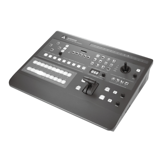
- Page 1 User’s Manual Multi-Format Video Switcher AV800HD...
- Page 2 AV800HD IMPORTANT SAFETY INSTRUCTIONS Read these instructions – All the safety and operating instructions should be read before this building-in space such as a book case or similar product is operated. unit, and remain a well ventilation conditions at Keep these instructions – The safety and open site.
- Page 3 AV800HD IMPORTANT NOTES Read First! Placement This device may interfere with radio and television ● Prior to the operation of this unit, please thoroughly reception. Do not use this device in the vicinity of read through the Owner’s Manual in its entirety, such receivers.
- Page 4 AV800HD Maintenance Before Using SD Card For everyday cleaning wipe the unit with a soft, Carefully insert the SD card all the way in---until it ● ● dry cloth or one that has been slightly dampened is firmly in place.
-
Page 5: Table Of Contents
AV800HD TABLE OF CONTENTS Introduction ........................5 Overview........................... 5 Features ........................... 5 Precaution for Use ......................6 Check the Included Items ....................7 Basic Setup ........................8 Power Supply ........................8 Ground Terminal ....................... 8 Connecting the Monitor ....................8 Configuratio ........................ - Page 6 AV800HD Multiview Screen Specs ....................20 Top Panel Operations ....................... 21 Transition Operation Mode (Operating Mode 1) ............... 21 PIP Operation Mode (Operating Mode 2) ................. 24 KEY Operation Mode (Operating Mode 3) ............... 27 DSK Operation ......................... 32 Output Fade Operation ..................... 33 Input Scaling ........................
-
Page 7: Introduction
The model offers 4 independent 3G-SDI inputs that can be previewed with no frame drop in Multiview screen. These SDI inputs can also be used as 2 3G SDI instead. The AV800HD includes onboard live audio and video recording capabilities to external USB 3.0 storage devices, allowing for 1080p at 60fps HD recording without the need for additional high-end... -
Page 8: Precaution For Use
AV800HD PRECAUTION FOR USE Handle carefully ● Do not drop the product, or subject it to strong shock or vibration. Do not carry or move the product by the T-Bar (fader lever). This is important to prevent trouble. Use the product in an ambient temperature of 32 °F to 95 °F (0 °C to 35 °C) ●... -
Page 9: Check The Included Items
Upon unboxing the product, please carefully inspect the included items, in the unlikely event of any missing or damaged items, please contact your authorized retailer/distributor for replacements. AV800HD Power Cable User’s Manual Multi-Format Video Switcher AV800HD AV800HD Owner’s Manual English... -
Page 10: Basic Setup
If you are unsure of the connection method, contact the nearest Asystems Service Center, or an authorized Asystems distributor for detailed information. Connecting the Monitor To begin operate the AV800HD, a monitor must be connected that supports Interface input to the connector shown below. Interface... -
Page 11: Configuratio
AV800HD CONFIGURATION Top View (Button Layout) 1. Setup Menu & Cursor Controls: Menu Button: Open or Close Setup Menu OSD. ● Directional Buttons (Up, Down, Right & Left): Use as cursor navigation control in Setup Menu. ● Left Arrow: Use to toggle Multiview Channel 7 and A display (When Setup Menu is closed). - Page 12 AV800HD 4. Memory Section: ● Memory LEDs (1 to 4): Illustrates current memory page number (Total of 32 sets memory, 8 sets per page.). Buttons 1 to 8: Select or save to memory location. ● Page Button: Select memory page number.
-
Page 13: Rear Panel (Input/Output Ports)
AV800HD 15. PIP Enable Button 1: Enable PIP form upper-left corner. ● Button 2: Enable PIP from lower-left corner. ● Button 3: Enable PIP form upper-right corner. ● Button 4: Enable PIP from lower-right corner. ● 16. KEY Section KEY SEL (Select) Button: Toggle KEY mod on and off. -
Page 14: Front View
AV800HD 5. Audio Out Stereo analog PGM audio output. ● 6. Audio In Stereo analog audio input. ● 7. Audio In USB digital audio input. ● 8. Ext Rec Storage USB 3.0 external mass storage device for PGM recording. ●... -
Page 15: Connecting External Equipment
AV800HD CONNECTING EXTERNAL EQUIPMENT Connect external equipment as shown in this chapter. For information on specific connection methods, refer to the following pages. Interface Interface Interface CAT5/6 Interface Interface CAT5/6 Interface Interface Interface CAT5/6 Interface Interface CAT5/6 Interface Interface Interface About Input Formats Signals of the formats shown below can be input from source equipment. -
Page 16: Connecting Source Equipment
Making SDI Connections AV800HD supports up to 4 3G-SDI. Connect SDI equipment such as video cameras or video decks to the SDI IN connectors. SDI inputs are default to cross-point channels 1 through 4 (Can be reconfigured to other cross-point channels). -
Page 17: Connecting A Computer Or Interface Equipment
AV800HD CONNECTING A COMPUTER OR Interface EQUIPMENT Making a Interface Connection Connect computers and video cameras capable of Interface output to the Interface IN connectors. Inputs are default to cross-point channels 5 through 8(Can be reconfigured to other cross-point channels). -
Page 18: Connecting Output Equipment
AV800HD CONNECTING OUTPUT EQUIPMENT Connecting a Projector Use the Interface AUX Out connector to connect to the input connector on the projector. Interface Interface 3 Interface 2 Interface 4 Interface Interface Interface Interface Connecting an External Recording Storage Connect recording storage device such as an external USB 3.0 hard disk to the USB 3.0 connector. EXT DRV LED on the top panel will light up indicating the device is ready to use. - Page 19 AV800HD Pin Assignment Tally 1 Connector Pin No. Signal Name Input/output Description PVW 1 Open collector output Tally output of CH 1 PVW PGM 1 Open collector output Tally output of CH 1 PGM PVW 2 Open collector output Tally output of CH 2 PVW...
-
Page 20: Basic Operation
AV800HD BASIC OPERATION In this section, you will be shown the essential controls and operations of each function, it serves as a basic tutorial for beginners, as well as a guideline for how to properly execute these commands. Power on Sequence AV800HD Copyright by ASYSTEMS All rights reserved. -
Page 21: Multiview Screen
AV800HD Multiview Screen CH7/A CH8/A CH7/A CH8/B Multiview Screen: At completion of system start up, Multiview screen will be displayed. 1. PVW Section (Preview Output): Depend on the mode of operation, PVW section has different function. • Wipe Pattern Transition Mode: The video selected on the inactive bus (standby) is shown here. If that bus becomes active, the selected video will become the new program output. -
Page 22: Multiview Screen Specs
AV800HD Multiview Screen Specs Multiview screen is your main system control screen, it recommended that you familiarize yourself with the following layout and operation procedures for optimal system performance. The Multiview Monitor splits the screen into ten windows to show multiple sources on a single monitor. You can check sources on the same monitor at the same time. -
Page 23: Top Panel Operations
AV800HD Top Panel Operations Transition Operation Mode (Operating Mode 1) ● Transition Operation Mode is the default mode at the beginning of each start up. Assign a Channel to PVW ● PST Buttons 1. Use PST button to assign a channel to PVW. - Page 24 AV800HD Assign a Channel to PGM PGM Buttons 1. Use PGM button to assign a channel to PGM. Channel 2 selected 2. Selected PGM button will light up in red; corresponded Multiview screen will have a red border around; selected channel content will be Red Boarder indicates Channel 2 displayed in PGM screen.
- Page 25 AV800HD Wipe Patterns By selecting a wipe pattern will switch the operating mode to Transition Operation Mode. By default, after system power up, it will automatically assumes default to Transition Operation Mode. 1. MIX is the default wipe pattern upon first power...
-
Page 26: Pip Operation Mode (Operating Mode 2)
AV800HD Program Transition Control Program Transition Control is used to swap contents between PVW and PGM channels. There are three ways of performing the transition, Auto transition and manual transition, giving you the total control and creative freedom to transition between input sources. - Page 27 AV800HD Assign PIP Source PIP Preview (PVW Screen) Use PGM cross-point buttons to assign main PIP source. Channel B cannot be used. CH7/A CH8/A CH7/A CH8/B Assign main PIP source PIP Preview (PVW Screen) Use PST cross-point buttons to assign PIP sub source.
- Page 28 AV800HD PIP Transition Operation 1. Use T-Bar, AUTO and CUT buttons to perform PIP transition. 2. Exit PIP Transition Operation: • Press one of Wipe Pattern button exit the PIP transition to Wipe Pattern transition. • Press KEY SEL button exit the PIP transition to KEY transition.
-
Page 29: Key Operation Mode (Operating Mode 3)
AV800HD KEY Operation Mode (Operating Mode 3) Press KEY SEL to enable Key Preview Mode. Multiview screen will switch to KEY Mode. Enable KEY Mode Scale/Size PIP/KEY LED is lit (Controls in KEY mode). Press SEL to toggle joystick controls between KEY and Camera. - Page 30 AV800HD KEY Source Selection 1. Use PGM cross-point buttons to assign Background Source. Channel B cannot be used. 2. Background is displayed in PGM screen. Background CH7/A CH8/A 3. Use PST cross-point buttons to assign Foreground CH7/A CH8/B Source. Channel B cannot be used.
- Page 31 AV800HD Custom KEY Filter Color Pick Up 1. KEY Preview consists of 3 items: • A: Eyedropper; use to pick up custom key filter color. • B: Custom Key Color indicator; illustrated in RGB Foreground format. • C: Current Key Filter Color; default to Green; other...
- Page 32 AV800HD KEY Transition Types 1. AUTO: Foreground fades into PGM according to defined transition time. MANUAL (T-Bar): Foreground fades into PGM AUTO KEY Transtion according the T-Bar movement speed. 3. CUT: Foreground instantly appears in PGM. Starting Transition Point 100% 4.
- Page 33 AV800HD Key Menu Setup R=000 G=252 B=010 GREEN C H2 C H2 Background C H5 C H5 CH7/A CH8/A CH7/A CH8/B Foreground Foreground 1. KEY Setup Menu will open automatically when KEY Mode is enabled. 2. Press MENU button or switch to other operating modes to close Setup Menu.
-
Page 34: Dsk Operation
AV800HD DSK Operation A DSK or downstream key is the ability to key independently or downstream from the switching buses, thus allowing the ability to mix and fade signals behind keyed lyrics or graphics. Using this feature, you can overlay logos, texts and subtitles onto the existing picture to produce videos that are high quality and professional. -
Page 35: Output Fade Operation
(LED off). CH7/A CH8/B THE END Applying Output Fade Input Scaling The AV800HD will automatically configure the sources of the input signals to fit the output format, manual input scaling is also available for fine tweak non-standard input formats English... - Page 36 AV800HD Setup Conditions The prerequisite conditions for input scaling adjustment are as followed. System must be in Wipe Pattern Transition Mode. ● Setup Menu is closed. ● Input sources are S1-4 and D1-4 (Multi-zoom channel cannot be adjusted). ● Input Scale Adjustment 1.
- Page 37 AV800HD Output Scaling As to input scaling, you can manually adjust the output scaling by following the steps listed below. Setup Conditions The prerequisite conditions for output scaling adjustment are as followed. Set joystick to output scale mode by pressing Scale/Size SEL button to “OUTPUT”.
-
Page 38: Scaling Adjustment Screen
Preset Memory The AV800HD stores up to 32 custom memory settings that you can easily switch on the fly depending on the situation Memory contents that will be save are as described below, for detailed information, please refer to the Preset Memory... -
Page 39: Camera Control
AV800HD Camera Control External camera can be controlled via RS422 port. The RS422 port configuration is located in the Setup Menu Camera control can be accessed in all operation modes. Press joystick “SEL” until “CAMERA” LED is lit. ● Use the “POSITION” joystick for camera motion ●... -
Page 40: Recording
CH7/A CH8/B 3. Press Stop Button to conclude the recording. File created will be saved. 4. The AV800HD will automatic generate a default file name for each recording. The default recording format will follow the pattern below. Recording in progress... -
Page 41: Playback
AV800HD Playback 1. Press Play/Pause Button to start playback operation. Playback Menu will be displayed at lower left corner of Multiview screen. Playback content will be shown in CH A screen. Playback at PAUSE state. PLAY indicator is flashing at; playback preview with PAUSE icon at lower right corner. -
Page 42: Setup Menu Operations
SETUP MENU OPERATIONS The AV800HD’s setting menus are displayed on the Multiview monitor. This section covers all the menu and sub-menu operations of the system settings, please refer to this section for any setting changes, the menu operations follow the flow described below. - Page 43 AV800HD I/O Setup Menu I/O Setup Menu manages your input/output source signals to their corresponding channels, please refer to the following steps for manual setup or adjustments Use ← → to select I/O SETUP option. ● Use ↑ ↓ to select “CHANNEL SETUP”; press “ENTER”...
- Page 44 AV800HD MULTI-ZOOM SETUP In Multi-Zoom, you are allowed to split one input channel into multiple channels. Each multi-zoom channel can be captured from any portion of the original source image. A maximum of 8 Multi-Zoom can be assigned. Multi-Zoom Enable Conditions: •...
- Page 45 AV800HD Multi-Zoom Area Selected Select a New Zoom Area CH7/A CH8/A CH7/A CH8/B Cross-Point Channel assigned to Multi-Zoom English...
- Page 46 AV800HD Audio Output Setup Audio output setup defines the source of PGM audio. 3 audio sources are available for PGM, if both external analog and USB audio are connected, USB will override external analog. • Default: Embedded audio from input video source.
- Page 47 AV800HD Video Output Setup Use ↑↓ to place cursor to Video Output Setup button, system will reboot each time a resolution change is executed. Press Enter to sub-menu selection. Use ←→ to select sub-menu options. The default system settings are: AUX 1 Resolution: 1080 ●...
- Page 48 AV800HD Frame Rate Selection Selection only applies to PGM (PAL) 60P (50P) ● 30P (25P) ● 30i (25i) ● NTSC Frame Rate Select Video System NTSC ● ● PAL Frame Rate Select English...
- Page 49 AV800HD Effects Setup Menu You can mix and edit effects in the Effect Menu to your preference and make smooth transitions between channels to make your program look professional. In the Effect Setup Menu you can edit the following settings:...
- Page 50 AV800HD 1. Transition Setup Menu. 2. Format: Press “ENTER” button to transition “FORMAT” selection; use ←→ buttons to navigate between selections Time, Frame and Time-Frame format. 3. At each format selection, use SEL knob to adjust Change Transition Format transition period: Time (0-9.99 seconds)
- Page 51 AV800HD PIP Setup In PIP setup, you are allowed to change the border width and color. 1. Selection: Width: PIP border width. 0~20 lines (Default 0, no ● border). Color: PIP border color. White, black, red, blue or ● green (Default white).
- Page 52 AV800HD Function Selections Filter color: Key extraction color. ● Filter Range: Use SEL knob to select 0-127 (Default: ● 25). Edge Sharpness: Use SEL knob to adjust 0-100 ● (Default: 0). Define foreground and background joining edge sharpness. 2. Key Filter Selection...
- Page 53 AV800HD DSK Setup DSK channel is fixed to Cross-Point Channel B (In Ext Key mode, it is the Key Fill), and can not be assigned to othe Cross-Point Channels. DSK menu will also pop-up when DSK SEL button is enabled.
- Page 54 AV800HD 3. SD File Selection: Follows the same steps as INT file select. 4. DSK Color Filter Selection: Black or white. 5. Edge Sharpness: 0-100 (Default: 0); joining edge sharpness. 6. EXT KEY: When enabled, the EXT KEY button will become solid.
- Page 55 AV800HD EXT KEY Enabled EXT KEY Source Selection Output Fade Setup In Output Fade Setup menu, you can edit and adjust the type of fade out screen of the output. Lower left corner displays the current output fade image, use SEL to make selection and adjustment.
- Page 56 AV800HD 1. Format (Solid Screen): Solid Screen: Built-in patterns. ● Int: Internal storage loading. ● Ext: SD loading. ● Freeze: Press to capture current PGM frame. ● Output Fade Format Select 2. Solid Screen Color: Black, white, red, green and blue.
- Page 57 AV800HD Camera Setup Menu Selections COM Port Configuratio COM1 Camera: RS422 camera control communication port ● Invert Y-Axis: Camera tilt control ● COM 2: RS232 remote control protocol port ● Camera COM 1 Setup 1. Please wait 30 seconds for the system to recognize the converter before any setting change begins.
- Page 58 AV800HD 4. Parity Selection None (Default) ● ● Even ● Parity Select 5. Stop Bit Selection 1 (Default) & 2. ● Stop Bit Select 6. Flow Control Selection None (Default) ● Xon/Xoff ● Hardware ● Flow Control Select Invert Y-Axis To invert joystick’s Y-Axis direction, Default at NORMAL.
- Page 59 ● Time Setup Menu File Management The AV800HD comes equipped with 5GB of internal storage, you can also connect external storage devices for file storage and video streaming. 1. Internal Storage (5 GB reserve space) INT is the root directory for internal storage.
- Page 60 HDCP function off and then on again to decode the signal. Otherwise, it will be able to display in the multiview screen. User must do this for all HDCP devices, unless devices were connected to AV800HD first and then turn on the HDCP function. English...
-
Page 61: Asystems Virtual Webcam Emulation Setup Guide
AV800HD Asystems Virtual Webcam Emulation Setup Guide Webcam Emulation In an age where everyday people are allowed to host their own channels talking about anything and everything of their interests by streaming videos live, a virtual webcam emulation has become an essential feature of compact video switchers. - Page 62 NETCAM IP address. Click “Yes”, and you will be prompted to enter the IP address that is assigned to your AV800HD in the System Status menu. English...
-
Page 63: Asystems Direct Streaming Setup Guide
AV800HD Asystems Direct Streaming Setup Guide The AV800HD supports direct stream on video streaming platforms and it follows standard Real Time Streaming Protocol (RTSP), which is a network control protocol designed for use in entertainment and communications systems to control streaming media servers. - Page 64 System Status The System Status menu gives a you glance of the entire system setup of your AV800HD. This is a where you’ll have a complete system setup information right on the screen and go back to corresponding sub-menus for adjustments, if necessary.
- Page 65 AV800HD Recall/Upgrade Within this menu, you’ll have the ability to reset a particular setting or the entire system setting to its default factory state. You can use the ENTER button to confirm selection. A confirmati n prompt screen will pop up. Use ← → to select between Yes and NO.
- Page 66 AV800HD Firmware Upgrade Asystems works diligently to keep improving our products and will release firmware updates periodically. This section describes the steps to perform the system updates. Keep user data: Use SEL knob to place cursor to Keep User Data.
- Page 67 AV800HD Backup The (Preset) Backup function allows user to manually backup the all 32 preset settings to the SD card, in the event the preset settings have been accidentally wiped, erased during firmware upgrade or overwritten due to human error, they can then be restored back to your accustomed preset settings.Press ENTER to go to sub-menu selection.
-
Page 68: System Specification
Supports Interface up to 1080p60; up to 70m distance (depending on cable quality and video resolution) *Not available in AV800HD-1 BNC, 3G-SDI Supports up to 1080p60 Supports 3G SDI *8 3G-SDI in AV800HD (V2) VIDEO OUTPUTS BNC, 3G-SDI Interface AUX 1 Out Supports Interface up to 1080p60 RJ-45,... - Page 69 AV800HD External Storage Standard SDHC slot. SD Card For still image input, firmware upgrade and preset backup External mass storage device for PGM recording. USB 3.0 Support up to 256TB* TALLY LIGHT DA-15 Tally 1 CH1 to 5 PVW & PGM Tally Out...
-
Page 70: Preset Memory Specification
AV800HD PRESET MEMORY SPECIFICATIONS Top Panel Specifications Data Default I. Transition Time Time: 0.00 to 9.99 sec; Frame: 000 to 999 frames; Time: 1.00; Frame: 030; Time Data Time-Frame: 1.00 to 9.nn, nn= max frame/sec Time-Frame: 1.00. II. Wipe Pattern... -
Page 71: Setup Menu Specification
AV800HD SETUP MENU SPECIFICATIONS Data Default I. I/O Setup A. Channel Setup Channel Input source S1-4, D1-4, X, and DSK S1-4, D1-4, X, and DSK S1-4, D1-4, X, and DSK S1-4, D1-4, X, and DSK S1-4, D1-4, X, and DSK... - Page 72 AV800HD D4, Frame Rate P30 and P60 Audio Source Default, USB and Analog Default Audio Delay 0.00 to 9.99 seconds 0.00 Input S1 to 4 Setup S1, Frame Rate P30 and P60 Audio Source Default, USB and Analog Default Audio Delay 0.00 to 9.99 seconds...
- Page 73 AV800HD II. Effects Setup Menu A. Transition Setup Format Time, Frame and Time-Frame Time Wipe Pattern Button 1 1 to 24 Wipe Pattern Button 2 1 to 24 Wipe Pattern Button 3 1 to 24 Wipe Pattern Button 4 1 to 24...
- Page 74 AV800HD D. DSK Setup Source Int, SD, CH1-8 and Ext Key Int fil Selected file “WELCOME” image fil SD fil Selected file Blank Filter Black and White Black Edge 0 to 100 Ext Key Int, SD and X (Off) III. Config Menu...
- Page 75 AV800HD IV. Camera Setup Menu A. Camera COM Setup Baud Rate 9600, 115200 and 384000 9600 Data 5, 6, 7 and 8 Parity None, Odd and Even None Stop 1 and 2 Flow Control None, Xon/Xoff and Hardware None B. Invert Y-Axis Setup...
-
Page 76: Glossary
AV800HD GLOSSARY Word Data Aspect Ratio The ratio between the horizontal and vertical dimensions of an image or screen. A spare bus which can be switched by signals other than the main line output signals. [Auxiliary Bus] The signals which are output from the internal color generator and used as the Background background image. - Page 77 AV800HD This function combines a sub screen image with the background image. [Picture-in-picture] The function for checking ahead of time the image which will be output after the next [Preview] transition. The image is output from the PVW system. The bus which always carries the program output signals.
- Page 80 www.asystems-sys.com...
Need help?
Do you have a question about the AV800HD and is the answer not in the manual?
Questions and answers