Sign In
Upload
Download
Table of Contents
Contents
Add to my manuals
Delete from my manuals
Share
URL of this page:
HTML Link:
Bookmark this page
Add
Manual will be automatically added to "My Manuals"
Print this page
×
Bookmark added
×
Added to my manuals
Manuals
Brands
Motorola Manuals
Cell Phone
TC55CH
User manual
Motorola TC55CH User Manual
Verizon
Hide thumbs
1
2
3
4
Table Of Contents
5
6
7
8
9
10
11
12
13
14
15
16
17
18
19
20
21
22
23
24
25
26
27
28
29
30
31
32
33
34
35
36
37
38
39
40
41
42
43
44
45
46
47
48
49
50
51
52
53
54
55
56
57
58
59
60
61
62
63
64
65
66
67
68
69
70
71
72
73
74
75
76
77
78
79
80
81
82
83
84
85
86
87
88
89
90
91
92
93
94
95
96
97
98
99
100
101
102
103
104
105
106
107
108
109
110
111
112
113
114
115
116
117
118
119
120
121
122
123
124
125
126
127
128
129
130
131
132
133
134
135
136
137
138
139
140
141
142
143
144
145
146
147
148
149
150
151
152
page
of
152
Go
/
152
Contents
Table of Contents
Troubleshooting
Bookmarks
Table of Contents
Revision History
Table of Contents
List of Tables
List of Figures
About this Guide
Configurations
Documentation Set
Chapter Descriptions
Icon Conventions
Notational Conventions
Related Documents
Service Information
Figure 1: Manufacturing Label Location
Chapter 1: Getting Started
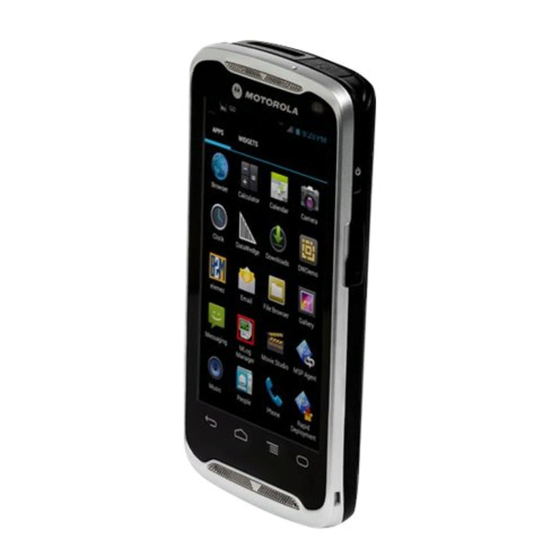
TC55 Features
Table 1: Front View Features
Figure 2: Front View
Table 2: Back View Features
Figure 3: Back View
Unpacking
Setup
Installing the SIM Card
Figure 4: Unlock SIM Card Holder
Figure 5: Install SIM Card
Installing an Optional Microsd Card
Figure 6: Close SIM Card Holder
Figure 7: Lock SIM Card Holder
Figure 8: Unlock Microsd Card Door
Figure 9: Insert Microsd Card
Installing the Battery
Figure 10: Lock SD Card Door
Figure 11: Inserting the 2,940 Mah Battery
Figure 12: Inserting the 4,410 Mah Battery
Figure 13: Install the Battery Cover
Charging the Battery
Charging the Main Battery
Figure 14: Secure Cover
Charging LED Status
Charging Temperature
Table 3: Charging LED Status
Figure 15: Connect the Rugged Charge Cable
Powering on the TC55
Replacing the 2,940 Mah Battery
Figure 16: Remove the Battery Cover
Figure 17: Remove 2,940 Mah Battery
Figure 18: Inserting the 2,940 Mah Battery
Figure 19: Align the Battery Cover
Replacing the 4,410 Mah Battery
Figure 20: Secure the Battery Cover
Figure 21: Remove the Battery Cover
Figure 22: Remove 4,410 Mah Battery
Figure 23: Inserting the 4,410 Mah Battery
Figure 24: Align the Battery Cover
Replacing the Microsd Card
Figure 25: Secure the Battery Cover
Figure 26: Unlock Microsd Card Cover
Figure 27: Insert Microsd Card
Battery Management
Monitor Battery Usage
Figure 28: Lock Microsd Card Cover
Low Battery Notification
Figure 29: Battery Screen
Figure 30: Low Battery Notification
Battery Optimization
Turning off the Radios
Setting the Date and Time
Figure 31: Battery Depleted Screen
General Sound Setting
Figure 32: Sounds Screen
Setting LED Notifications
Figure 33: Volumes Dialog Box
Figure 34: LED Options Dialog Box
Chapter 2: Using the TC55
Home Screen
Figure 35: Home Screen
Status Bar
Table 4: Home Screen Items
Table 5: Home Screen Items
Figure 36: Notification and Status Icons
Status Icons
Table 6: Status Icons
Notification Icons
Table 7: Notification Icons
Managing Notifications
Application Shortcuts and Widgets
Adding an Application or Widget to the Home Screen
Moving Items on the Home Screen
Removing an App or Widget from the Home Screen
Figure 37: Notification Panel
Folders
Creating a Folder
Naming Folders
Removing a Folder
Changing the Home Screen Wallpaper
Figure 38: Open Folder
Figure 39: Renamed Folder
Using the Touchscreen
Using the On-Screen Keyboard
Applications
Table 8: Applications
Accessing Applications
Switching between Recent Applications
Figure 40: APPS Window
Un-Locking the Screen
Single User Mode
Figure 41: Recently Used Applications
Figure 42: Lock Screen
Figure 43: PIN Screen
Multiuser Mode
Multiuser Login
Figure 44: Pattern Screen
Figure 45: Password Screen
Multiuser Logout
Resetting the Device
Performing a Soft Reset
Performing a Hard Reset
Figure 46: Multiple User Log in Screen
Suspend Mode
Figure 47: Three Button Reset
Figure 48: Lock Screen
Chapter 3: Calls
Making a Call Using the Dialer
Figure 49: Insert Wired Headset Plug
Figure 50: Dialer Screen
Dialer Dialing Options
Figure 51: Call in Progress
Making a Call Using Contacts
Making a Call Using Call History
Figure 52: Dialer Contacts Tab
Making a Conference Call
Figure 53: Call History Tab
Figure 54: Two Calls
Figure 55: Merged Calls
Making a Call Using a Bluetooth Headset
Answering Calls
Figure 56: Un-Merge Calls
Figure 57: Incoming Call Screen
Figure 58: Select Answer Options
Answering Calls with a Bluetooth Headset
Call Settings
Figure 59: Incoming Call Screen
Chapter 4: Applications
File Browser
Figure 60: File Browser Screen
Messaging
Sending a Text Message
Figure 61: New Text Message Screen
Sending a Multimedia Message
Figure 62: New Multimedia Message Screen
People
Adding People
Editing People
Deleting People
Voice Dialer
Calling a Person by Name
Redialing Previous Call
Dialing by Number
Opening an Application
Figure 63: Voice Dialer Window
Camera
Taking Photos
Figure 64: Camera Mode
Taking a Panoramic Photo
Figure 65: Panoramic Mode
Recording Videos
Camera Settings
Figure 66: Video Mode
Video Settings
Gallery
Working with Albums
Figure 67: Gallery - Albums
Figure 68: Photos Inside an Album
Share an Album
Get Album Information
Deleting an Album
Working with Photos
Viewing and Browsing Photos
Rotating a Photo
Cropping a Photo
Figure 69: Photo Example
Setting a Photo as a Contact Icon
Get Photo Information
Figure 70: Cropping Tool
Share a Photo
Deleting a Photo
Working with Videos
Watching Videos
Sharing a Video
Deleting a Video
Figure 71: Video Example
Movie Studio
Datawedge Demonstration
Figure 72: Movie Studio Application
Sound Recorder
Table 9: Datawedge Demonstration Icons
Figure 73: Datawedge Demonstration Window
Elemez
Figure 74: Sound Recorder Application
Figure 75: Elemez Application
Disabling Elemez Data Collection
Enabling Elemez Data Collection
Mlog Manager
Figure 76: Mlog Manager
Chapter 5: Data Capture
Linear Imager
Digital Camera
CS3070 Bluetooth Scanner
RS507 Hands-Free Imager
Scanning Considerations
Figure 77: CS3070 Bluetooth Scanner
Figure 78: RS507 Hands-Free Imager
Bar Code Capture with Linear Imager
Figure 79: Scanning
Figure 80: Aiming Pattern
Bar Code Capture with Integrated Camera
Bar Code Capture with CS3070 Bluetooth Scanner
Figure 81: Application with Preview Window
Bar Code Capture with RS507 Hands-Free Imager
Figure 82: CS3070 Scanning
Figure 83: Linear Scanner Aiming Pattern
Figure 84: Bar Code Scanning with RS507
Figure 85: Aiming Pattern
Figure 86: Pick List Mode with Multiple Bar Codes in Aiming Pattern
Datawedge
Enabling Datawedge
Disabling Datawedge
Chapter 6: Wireless
Wireless Wide Area Networks
Sharing the Mobile Data Connection
USB Tethering
Bluetooth Tethering
Portable Wi-Fi Hotspot
Data Usage
Figure 87: Set up Wi-Fi Hotspot Dialog Box
Disabling Data When Roaming
Figure 88: Data Usage Screen
Limiting Data Connection to 2G Networks
Locking the SIM Card
Figure 89: Enter PIN to Lock SIM Card
Editing the Access Point Name
Wireless Local Area Networks
Scan and Connect to a Wi-Fi Network
Figure 90: Settings Screen
Figure 91: Wi-Fi Screen
Configuring a Wi-Fi Network
Figure 92: WLAN Network Security Dialog Boxes
Manually Adding a Wi-Fi Network
Configuring for a Proxy Server
Configuring the Device to Use a Static IP Address
Figure 93: Proxy Settings
Figure 94: Static IP Settings
Advanced Wi-Fi Settings
WLAN Configuration
Modifying a Wi-Fi Network
Connecting to a Wi-Fi Network Using WPS
Remove a Wi-Fi Network
Bluetooth
Adaptive Frequency Hopping
Security
Bluetooth Profiles
Bluetooth Power States
Bluetooth Radio Power
Enabling Bluetooth
Disabling Bluetooth
Discovering Bluetooth Device(S)
Figure 95: Bluetooth Pairing - Enter PIN
Figure 96: Bluetooth Pairing - Smart Pairing
Changing the Bluetooth Name
Connecting to a Bluetooth Device
Selecting Profiles on the Bluetooth Device
Unpairing a Bluetooth Device
Pairing with the CS3070
CS3070 Numeric Bar Codes for PIN Entry
Figure 97: Bluetooth Keyboard Emulation (HID) Bar Code
Pairing the RS507 Hands-Fee Imager
Figure 98: RS507 Bluetooth HID Bar Code
Near Field Communications
Sharing Information Using NFC
Figure 99: Sharing Data Using NFC
Communication Using NFC
Pairing with NFC Enabled Bluetooth Devices
Figure 100: Communication with NFC Chip, Tag or Card
Figure 101: Pairing with NFC Enabled Device
Chapter 7: Accessories
TC55 Accessories
Table 10: TC55 Accessories
Micro USB Cable
Figure 102: Using the Micro USB Cable
Rugged Charge Cable
Figure 103: Rugged Charge Cable
Figure 104: Connect Rugged Charge Cable to TC55
Figure 105: Connect to Power
Figure 106: Removing the Rugged Charge Cable
Five Slot Charge Only Cradle
Figure 107: Five Slot Charge Only Cradle
Vehicle Charge Cradle
Installing Vehicle Cradle on Windshield
Figure 108: Remove Cup Insert
Figure 109: Windshield Installation
Figure 110: Move Level Toward Windshield
Figure 111: Insert TC55 into Vehicle Charge Cradle
Figure 112: Tighten Nut
Figure 113: Connect Auto Charge Cable to Vehicle Charge Cradle
Removing the Device from the Vehicle Cradle
Figure 114: Cable Retention
Dock Settings
Figure 115: Remove TC55 from Vehicle Cradle
Figure 116: Dock Screen
Figure 117: Dock Settings Screen
Installing the Protective Boot
Figure 118: Protective Boot
Figure 119: Insert Top of TC55 into Boot
Figure 120: Insert Bottom of TC55 into Boot
Attaching the Stylus to the Protective Boot
Figure 121: Insert Tether into Stylus
Figure 122: Feed Stylus through Tether Loop
Figure 123: Insert Stylus Point into Mounting Hole
Figure 124: Lock Stylus into Place
Holster
Figure 125: Style in Protective Boot
Figure 126: Holster
Figure 127: Inserting the TC55 with 2,490 Mah Battery into the Holster
Figure 128: Inserting the TC55 with 4,410 Mah Battery into the Holster
Figure 129: Stylus in Holster
Advertisement
Quick Links
Download this manual
TC55 VERIZON USER GUIDE
February 2014
MN000xxxA01
©
2014 Motorola Solutions, Inc. All rights reserved
Table of
Contents
Previous
Page
Next
Page
1
2
3
4
5
Advertisement
Table of Contents
Troubleshooting
Chapter 8: Maintenance and Troubleshooting
141
Troubleshooting
144
Need help?
Do you have a question about the TC55CH and is the answer not in the manual?
Ask a question
Questions and answers
Related Manuals for Motorola TC55CH
Cell Phone Motorola TC55 User Manual
Mobile phone (160 pages)
Handhelds Motorola TC55 Integrator Manual
(140 pages)
PDA Motorola TC55AH Quick Start Manual
(13 pages)
Handhelds Motorola TC55 Quick Start Manual
(13 pages)
Cell Phone Motorola TC75 Quick Start Manual
(2 pages)
Cell Phone Motorola Telario TC3000 User Manual
Portable communicator (68 pages)
Cell Phone Motorola TC55BH User Manual
Verizon (152 pages)
Cell Phone Motorola P7382i User Manual
Digital wireless telephone (118 pages)
Cell Phone Motorola Tundra VA76r User Manual
Motorola cell phone user manual (230 pages)
Cell Phone Motorola T200 Service Manual
(77 pages)
Cell Phone MOTOROLA T720 User Manual
Cdma wireless phone (196 pages)
Cell Phone Motorola T720 Manual
Gsm wireless phone (83 pages)
Cell Phone Motorola StarTAC Owner's Manual
Motorola cell phone owner's manual (140 pages)
Cell Phone Motorola Droid Maxx 2 User Manual
(64 pages)
Cell Phone Motorola MOTOKEY MINI Manual
With dual chip (70 pages)
Cell Phone Motorola ThinkPhone User Manual
(368 pages)
This manual is also suitable for:
Tc55
Tc55ah
Tc55bh
Table of Contents
Print
Rename the bookmark
Delete bookmark?
Delete from my manuals?
Login
Sign In
OR
Sign in with Facebook
Sign in with Google
Upload manual
Upload from disk
Upload from URL


Need help?
Do you have a question about the TC55CH and is the answer not in the manual?
Questions and answers