Table of Contents
Advertisement
Advertisement
Table of Contents

Related Manuals for Motorola T200


Summary of Contents for Motorola T200
- Page 1 T200 / T2688 Level 1 & 2 Service Manual Rev 1.2...
-
Page 2: Table Of Contents
T200 / T2688 CONTENTS Page Number SECTION 1: GENERAL Introduction Motorola service policy for T200 in warranty General Safety Information SECTION 2: T200 DESCRIPTION Specifications of T200 T200 Overview Connector Pinout Talk time, Weight and Volume Matrix Battery Charging Times... - Page 3 T200 / T2688 SECTION 6: REPAIR & TEST PROCEDURES Repair introduction Mechanical repairs Basic modular troubleshooting Software Upgrade Flexing Testing on DM Tools SECTION 7: ACCESSORIES Accessory Introduction SECTION 8: SALES MODELS Sales Models Numbers SECTION 9: GLOSSARY OF TERMS...
-
Page 4: Section 1: General
T200 / T2688 SECTION 1: GENERAL of 51 GSM Field Service Support... -
Page 5: Introduction
This manual is intended for use by technicians familiar with similar types of equipment. It contains all service information required for the equipment described and is current as of the printing date. This manual is intended for use with the T200. The T200 is electrically and physically identical to the Asian model the T2688. -
Page 6: Motorola Service Policy For T200 In Warranty
1.2.3 Product Support Customers original units will be repaired but not refurbished as standard. Appointed Motorola Service Hubs will perform warranty and non-warranty field service for level 2 (assemblies) and level 3 (limited PCB component). The Motorola HTC centres will perform level 4 (full component) repairs. -
Page 7: General Safety Information
In standby mode the mobile telephone will automatically transmit to acknowledge a call if it is not turned off. • Refer to the appropriate section of the product user manual for additional pertinent safety information • All equipment should be serviced only by a Motorola qualified technician. of 51 GSM Field Service Support... -
Page 8: Section 2: T200 Description
T200 / T2688 SECTION 2: T200 DESCRIPTION of 51 GSM Field Service Support... -
Page 9: Specifications Of T200
T200 / T2688 Specifications of T200 General Function Specification Frequency Range GSM 890-915 MHz TX 915-960 MHz RX Frequency Range DCS 1710-1785 MHz Tx 1805-1880 MHz Rx Channel Spacing 200 kHz Channels 124GSM/374 DCS carriers with 8 channels per carrier Modulation GMSK at BT = 0.3... -
Page 10: T200 Overview
T200 / T2688 T200 Overview The T200 is of the Dual Band technology range allowing roaming using the GSM 900 / 1800 bands. The unit is an OEM product, and is the same product, mechanicaly and physically as the Asian T2688. - Page 11 Connectivity – The t200 supports Windows 95 / 98 / NT in data service. No PCMCIA card is required of 51 GSM Field Service Support...
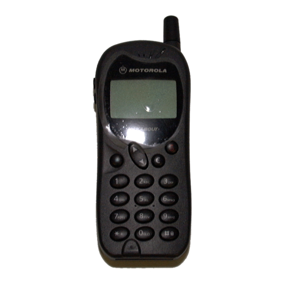
- Page 12 T200 / T2688 Fig 2.1 Mechanical pictorial Overview Lens w/ Talkabout Menu Microphone logo access key Socket Speaker Ports Accessory Antenna Volume Charger Keys Screw Port Locations Lanyard Loop Battery Retaining Contacts Contacts slide of 51 GSM Field Service Support...
-
Page 13: Connector Pinout
T200 / T2688 2.3 Connector Pinouts • I06 • CHGERP • GND Charger Socket Pin Layout 1.Ext AUD MIC IN / JTAG TMS Use 2.JTAG TRST Use 3.GND / JTAG TMK Use 4.Auxiliary Audio Out / JTAG TDI 5.RS232 – DSR 6.RS232_RXD... -
Page 14: Battery Charging Times
T200 / T2688 Battery Charging Times Identical to Leap, maximum charge times shown. Battery Charge time with Switch Charge time with Linear Mode Travel charger to 95% Travel charger to 95% 600 mAh LiIon 95 minutes 160 minutes 650mAh Ni MH... -
Page 15: Section 3: Feature List
T200 / T2688 SECTION 3: FEATURE LIST of 51 GSM Field Service Support... -
Page 16: List Of Features Available
T200 / T2688 List of Features Available Below is the list of Menu functions available at present. Pressing the following key can access the menu option: Menu Generation Menu Call Phone Book Messages Services Generation Menu Generation Menu Phone Security... -
Page 17: Messages
T200 / T2688 MESSAGES Inbox New Message Outbox Voicemail 1.On Receive Broadcast 2.Off Topics Settings Route Center 1.English ↓ Language Delete All 16.Chinese Valid Period 1….1 Hour 2….6 Hours 3….12 Hours Voice Mail 4….1 day 5….1 Week 1.On Reply path 2.Off... -
Page 18: Call Services
T200 / T2688 CALL SERVICES Call Divert Divert Voice When Busy Call Barring All Outgoing If No Reply Int’l Out Number 1.Activate 2.Cancel Unreachable 3.Status Int’l Exc. Home message Number Divert Cond. 1.Activate All Incoming 2.Cancel message Divert Data In when Roam... -
Page 19: Phone Settings
T200 / T2688 PHONE SETTINGS Backlight 1.Automatic 2.Prompt Auto Redial 3.Off 1.Auto Answer by 2.Any Key 3.Send Key Key Lock Confirm? 1.English ↓ Language 3.Indonesian 1.On Time Alert 2.Off Restore Phone Code? 1.On Display 2.Animation 1 3.Animation 2 NETWORKS Automatic Manual 1.Available Networks... -
Page 20: Security
T200 / T2688 SECURITY 1.On Code Status Pin Code 2.Off Change Code Pin Code PIN 2 Enter Code Phone Code Enter Password Network Code View Fixed Dial 1.On Set Status 2.Off Modify Enter PIN 2 1.On SIM Lock Set Status 2.Off... -
Page 21: Tools
T200 / T2688 TOOLS 1.On Set Alarm 2.Off Set Time 1.On 2.Off Calender Calculator of 51 GSM Field Service Support... -
Page 22: Section 4: Disassembly & Parts
T200 / T2688 SECTION 4: DISASSEMBLY & PARTS of 51 GSM Field Service Support... -
Page 23: Dissasembly Introduction
T200 / T2688 4.1 Disassembly Introduction The T200 is held together by 4 screws. 1 of these screws should be placed under the warranty seal, on the RH side of the phone rear facing towards you, antenna up). Ensure that a properly grounded high impedance conductive wrist strap is used whilst performing any tasks during the disassembly and assembly of the unit Avoid stressing the plastics in any way to avoid damage to either the plastics or internal components. - Page 24 T200 / T2688 1. Turn off the telephone. 3. Using a T5 Torx driver 2. Slide down the battery latch, and remove the 4 retaining remove the battery pack from screws. the housing. 5. Carefully lift the main 4. Unclip the 2 snap fits from the...
- Page 25 T200 / T2688 6. Insert the pointed end of plastic tool 5. Remove Volume buttons below speaker and pull upwards. by pulling upwards. Replace with new speaker after removal. 9. Remove keypad from front housing. of 51 GSM Field Service Support...
-
Page 26: Exploded Parts Diagram
T200 / T2688 Exploded Parts Diagram of 51 GSM Field Service Support... -
Page 27: Part Numbers
T200 / T2688 4.6 Part Numbers *For Part numbers of other variants please consult Level 1&2 parts list) Item Part number Description 20.F0075.014 System connector 22.10128.006 SIM card connector 22.80019.051 Vibrator motor 23.40046.001 Speaker 23.60016.041 Buzzer 23.42007.031 Microphone 25.90012.001 Antenna 34.G0110.001... -
Page 28: Section 5: Sim Cards And Security
T200 / T2688 SECTION 5: SIM CARDS AND SECURITY of 51 GSM Field Service Support... -
Page 29: Manual Test Mode
T200 / T2688 5.1 Manual Test Mode The GSM Motorola T200 is equipped with a manual test mode capability. This capability allows service personnel to take control of the unit, and by entering certain keypad commands, make the unit performs desired functions. -
Page 30: Gsm Test Command
T200 / T2688 5.4 GSM Test Commands This is a list of Level 1 and 2 Manaul Test commands available to the T2688 / T200 GSM Test Commands 1)*#300# OK List the Software and Hard ware version 2)*#301# OK Full Keypads functional Test... -
Page 31: Identity And Security
The mechanical Serial Number (MSN) is an individual unit identity number and will remain with the unit throughout the life of the unit. The MSN can be used to log and track a unit on Motorola’s EPPRS system. The MSN is divided into 4 sections. -
Page 32: Section 6: Repair & Test Procedures
T200 / T2688 SECTION 6: REPAIR AND TEST PROCEDURES of 51 GSM Field Service Support... -
Page 33: Repair Introduction
T200 / T2688 6.1 Repair Introduction The T200 is divided into 2 main sections when it comes to part replacability: The housings which contains the speaker, keypad and the Volume Buttons , the main PCB which contains RF / Logic circuitry and the keypad interface and the display. - Page 34 T200 / T2688 Repair Chart Table 2. GSM T200 Cellular Telephone: Troubleshooting and Repair Chart. (Assembly Replacement Level). SYMPTOM PROBABLE CAUSE VERIFICATION AND REMEDY Personal telephone will not turn on or a) Battery pack either Measure battery. If the battery voltage is <3.6V dc,...
-
Page 35: Software Upgrade
T200 / T2688 SYMPTOM PROBABLE CAUSE VERIFICATION AND REMEDY 7. Personal telephone will not a) SIM card defective Initially check that the contacts on the card are not recognize/accept SIM card dirty and that the SIM retention latch is pushed fully across. -
Page 36: Testing On Dm Tools
To then use flexing tools, the database should be changed to the later version, in this case 701214.bin The software for the T205 is 7013xx and for the T200 it is 7012xx The selection of the Boot file is as above The Flash file is derived from the s/w version as above... - Page 37 T200 / T2688 The database file is a filename.bin configuration, and again is derived from the s/w version. (In this case 701314.bin) Selecting the Files option on the tool bar may change all the files. Flashing Procedure STEP 1 After selecting the correct files, plug phone into cable but DO NOT power on. Then hit the download button.
- Page 38 T200 / T2688 Follow instruction’s above to flex phone. Flexing Procedure Select Service from tool bar and choose the Flex option to obtain the following screen. The flex settings are loaded from a file with designation (.fle ) and is known as FlexOption Profile. The load option is obtained by right clicking the mouse on the DM Tools’s window, and then selecting...
- Page 39 T200 / T2688 Flexing options screen. *The flex options are password protected and can not be changed manually unless the key and password are known. TEST COMMANDS Select View from tool bar and highlight MMI Test to obtain the following screen.
-
Page 40: Section 7: Accessories
T200 / T2688 SECTION 7: ACCESSORIES of 51 GSM Field Service Support... - Page 41 T200 / T2688 7.1 Introduction: The following is a short description of accessories available for the T200 that are currently available. Switch mode Travel Charger • Input: 90-260V, varies by plug type for each country, AC • Output: 6V, 750 mA Linear Travel Charger •...
-
Page 42: Section 8: Sales Models
T200 / T2688 SECTION 8: SALES MODEL NUMBERS of 51 GSM Field Service Support... -
Page 43: Sales Models Numbers
T200 / T2688 Sales Model Numbers Part Number of T200 with T-options Country T-option API p/n Color Moto p/n Descripton Australia T948UB 99.G0521.BOF Copper Orange SA2143AE5B1 SA2143AE5B1,AU ORG Telstra T948UB 99.G0521.BGF Misty Green SA2143AF5B1 SA2143AF5B1,AU GRN T948UB 99.G0521.BIF Teal Ice... - Page 44 T200 / T2688 Maly/SGP T948UP 99.G0521.POH Copper Orange SA2150AE5B1 SA2150AE5B1,SG ORG T948UP 99.G0521.PGH Misty Green SA2150AF5B1 SA2150AF5B1,SG GRN T948UP 99.G0521.PIH Teal Ice SA2150AG5B1 SA2150AG5B1,SG ICE T948UP 99.G0521.PBH Elec Blue SA2150AJ3B1 SA2150AJ3B1,SG EBU Maly/SGP T948UQ 99.G0521.QOH Copper Orange SA2150AE5B1 SA2150AE5B1,SG ORG T948UQ 99.G0521.QGH Misty Green...
- Page 45 T200 / T2688 Part Number of T200 with SIM Lock Country T-option API p/n Color Moto p/n Descripton Thailand AIS/DPC 99.G0521.AOB Copper Orange SA2145AE5X3 SA2145AE5X3,THA ORG AIS/DPC 99.G0521.AGB Misty Green SA2145AF5X3 SA2145AF5X3,THA GRN AIS/DPC 99.G0521.AIB Teal Ice SA2145AG5X3 SA2145AG5X3,THA ICE AIS/DPC 99.G0521.ABB Elec Blue...
-
Page 46: Section 9: Glossary Of Terms
T200 / T2688 SECTION 9: GLOSSARY OF TERMS of 51 GSM Field Service Support... -
Page 47: List Of Abbreviations
T200 / T2688 9.1 List of Abbreviations Those marked ** are Motorola specific abbreviations. µBGA Micro Ball Grid Array A Interface Interface between MSC and BSS Authentication algorithm Stream cipher algorithm ciphering key generating algorithm Access Burst A-bis Interface between BSC and BTS... - Page 48 T200 / T2688 COLP Connected Line identification Presentation COLR Connected Line identification Restriction CONF Conference Call add on CSPDN Circuit Switched Public Data Network Closed User Group Call Waiting Dummy Burst Distributed Base Station ** DCCH Dedicated Control Channel Detach...
- Page 49 T200 / T2688 HPLMN Home PLMN Hand Portable Unit Half Rate Hopping Sequence Number Information (frames) International Alphanumeric 5 Identification IMEI International Mobile Equipment Identity Immediate assignment message IMSI International Mobile Subscriber Identity Intelligent Network INDY Iridium 9500 handset IrDA...
- Page 50 T200 / T2688 NAMPS North American-Advance Mobile Phone System Normal Burst Network Elements Norme European de Telecommunications Network Management Network Management Center O&M Operations and Maintenance OACSU Off Air Call Set-Up Outgoing Calls Barred OMAP Operations and Maintenance Application Part (previously was OAMP)
- Page 51 T200 / T2688 SMSCB Short Message Service Call Broadcast SeND Signaling Point SRES Signed RESponse (authentication) Supplementary Service System Simulator Signaling Transfer Point SYSGEN SYStem GENeration Terminal Adapter Timing Advance TCAP Transaction Capabilities Application Part Traffic Channel TCH/F A full rate TCH...
-
Page 52: Circuit Description
Topaz T2688/T200, T2988/T205 L3 Circuit Description T2688/T200 T2988/T205 Level 3 Circuit Description 01 / 03 / 01 V1.3 Motorola Proprietary Information... - Page 53 Topaz T2688/T200, T2988/T205 L3 Circuit Description RECEIVE 1. Received GSM 900 frequency enters the unit at the Antenna ANT1 L501 / L502 / L503 provide matching 3. The signal then enters mechanical Auxiliary RF port U113. When a load (50? is placed into the socket the RF will be diverted into or out of U113).
- Page 54 Topaz T2688/T200, T2988/T205 L3 Circuit Description also allows the DC offsets of the IQ demodulator to be measured and then cancelled out. The below matrix shows the truth table for the signals involved and the states of the receiver path.
- Page 55 Topaz T2688/T200, T2988/T205 L3 Circuit Description 9. The balanced signal is then fed into U603 Pins1&2 for GSM and Pins 47 & 48 DCS. Within the U603 the received signal will now be mixed with the RX VCO to produce the 1 IF Frequency of 225.067Mhz.
- Page 56 Topaz T2688/T200, T2988/T205 L3 Circuit Description 16. Within the VEGA IC the path of the base-band RXI & Q data from the TX / RX IC takes the following route. Calibration Offset Anti-Aliasing Sigma / Delta Digital Filters: ? 24 Filter ADC @ 6.5MHz...
- Page 57 Topaz T2688/T200, T2988/T205 L3 Circuit Description 21. Within Gemini general GSM processing takes place, such as: De-Interleaving : Interleaving is a way in which the information that is to be transmitted is jumbled around before it is sent i.e. If we wish to send the information ‘They must read this’...
- Page 58 Topaz T2688/T200, T2988/T205 L3 Circuit Description 23. The processed digital audio is received from the Gemini at 8Khz, from here the signal is interpolated within a speech-digital infinite duration impulse response filter (IIR) (i.e. that is, for the data coming in, the adjacent bits of the data being looked at are all synchronised and an average taken.
- Page 59 Topaz T2688/T200, T2988/T205 L3 Circuit Description TRANSMIT 30. There are 2 sources of input audio: 31. Auxiliary Microphone is fed in through J40 External Connector Pin1 and is fed through Jumper Connector J8 (JTAG Use), and is amplified through the BQ5 circuit, supported by the voltage DVCC.
- Page 60 Topaz T2688/T200, T2988/T205 L3 Circuit Description 40. The processed information is sent along the Serial Base-band interface, and is fed into a register before being differentially encoded. The encoded signal is then applied to a Sin / Cosine look up ROM where the GMSK TX I & Q ‘words’ are generated (interpolation ratio of 16) 41.
- Page 61 Topaz T2688/T200, T2988/T205 L3 Circuit Description 48. These 2 paths are then summed to give a single IF modulated signal, which is then amplified. 49. From here the output current used to drive the TXVCO will be generated. The feedback from the TXVCO (DCS or GSM) is mixed with the RXVCO frequency to produce a reference frequency of 270Mhz.
- Page 62 Topaz T2688/T200, T2988/T205 L3 Circuit Description 59. Power Control is achieved in the following way: RAMP is connected to the Gain Control circuit U202 Pin 3. This is the positive input of the comparator. This is the same ideology as the AOC line in Whitecap products.
- Page 63 Topaz T2688/T200, T2988/T205 L3 Circuit Description VEGA IC and has a range of approximately 1.2V – 1.5V. The Oscillator supply is generated from the Base-band Voltage Regulator U27 Pin 24 (VTCXO 2.8V). The 13Mhz is buffered by IC402 before being O/P as 13MHz to...
- Page 64 Topaz T2688/T200, T2988/T205 L3 Circuit Description These are: ? Power on generated by set alarm, which is generated from the RTC (the alarm is set into the menu structure of the phone). Pin 2 ? IO2, software originated power on from Gemini Pin 112.
- Page 65 Topaz T2688/T200, T2988/T205 L3 Circuit Description 85. This will began to charge the battery through BQ3. (BQ3 fully open) The voltage divider R111 and R112 puts a voltage of 4V onto the source of BQ6. During this time will be charged (approximate charging time is 3 – 5 Seconds.
- Page 66 Topaz T2688/T200, T2988/T205 L3 Circuit Description Display 95. The LCD module is a 98 X 64, Chip on Glass device and measures 37 x 33mm with a polyamide foil connection to the PCB through U24. Support for the LCD is through DVCC.
- Page 67 Topaz T2688/T200, T2988/T205 L3 Circuit Description 106. The keypad matrix is as follows: Function COL0 COL1 COL2 COL3 LEFT RIGHT No Matrix used S16 switches VBAT directly onto the PWR signal to power up NO / CLR / the unit.
- Page 68 There is no other hardware difference to the product. PCB is the same and other mechanical parts are the same. Software is different – Version 3.X is Refresh software with additional features for T2988 (Asia) and T200 (EMEA) Additional features covered are 1. WAP 2.
- Page 69 RX MID CHANNELS GSM: CH 62 -- 947,4 MHz CONTROL SWITCH U502 CALIBRATION PA_ON DCS: CH 700 -- 1842,8MHz See Circuit description Page 2 for Logic ANT 1 RF PORT Control truth table. TX / RX IC RFIN1 IC501 U603 RFIN2 TX_ON HD155121F...
- Page 70 (AGCPRG) AGCA PA_ON ACCIN GEMINI (CLOCK) SYNCLK (DATA) SYNDAT 2, 4 BCLKR (SYNPRG) SYNENA VBAT From Gemini 5, 6 To VEGA ROW4 7, 8 BFSR S_I/O DSP CORE VFSRX S_RST 9, 10 VCLKRX To / From VEGA Backlights (LEAD) Interface From Gemini 11, 12 S_PWST...
- Page 75 VBAT [NO] [CLEAR] TP27 [PWR] AVCC DVCC PVCC18 VBAT AVCC 0.1UF 0.1UF DVCC TP24 DAN222 FUSE(0603) TP53 TP54 TP55 VTCXO 0.1UF 0.1UF IOPN11 RB520S-30 0.1UF 0.1UF 0.1UF 0.1UF AGND BGND VBAT 10UF(T 6.3V) 10UF(T 6.3V) 0.1UF 0.1UF LCDRST TP30 BUZZER2 10UF(T 6.3V) AGND BGND...
- Page 76 TXON GSM_RX EFCH9418MTY6 RXON2 U601 DCS_RX C602 RXON1 U602 C601 EFCH9418MTY6 RF2V8 C604 C652 C603 L604 C653 0.1u C605 C606 R605 TX2V8 RF2V8 SYN2V8 C612 L605 470R C607 C608 R607 L606 C301 C302 L607 C609 100p 0.1u IC301 C610 0805C 0805C C613 L608...
- Page 77 .3 Silence Prd .4 Supp Prd .5 In Volume .6 Out Volume .7 Icon .8 Image .9 Animation 8)#303# OK Settings Saved* 9)#400# OK ADC, Cal val* use with care - contains cal factors Thomas Tan 05/08/00 Motorola Internal Use only...
Need help?
Do you have a question about the T200 and is the answer not in the manual?
Questions and answers