Table of Contents
Advertisement
Quick Links
http://www.narda-sts.it
User's Manual
SERIAL NUMBER OF THE INSTRUMENT
You can find the Serial Number on the bottom cover of the instrument.
The Serial Number is in the form: 000XY00000.
The first three digits and the two letters are the Serial Number prefix, the last five
digits are the Serial Number suffix. The prefix is the same for identical instruments, it
changes only when a configuration change is made to the instrument.
The suffix is different for each instrument
Document EHP50GEN-81007-1.71 – Copyright © NARDA 2018
Sales & Support:
NARDA
Via Leonardo da Vinci, 21/23
Safety
20090 Segrate (MI) - ITALY
Test
Tel.: +39 02 2699871
Solutions
Fax: +39 02 26998700
S.r.l. Socio Unico
EHP-50G
ELECTRIC AND MAGNETIC
FIELD PROBE - ANALYZER
From 1 Hz up to 400 kHz
Manufacturing Plant:
Via Benessea, 29/B
17035
Cisano sul Neva (SV)
Tel.: +39 0182 58641
Fax: +39 0182 586400
Advertisement
Table of Contents

Related Manuals for NARDA EHP-50-G


Summary of Contents for NARDA EHP-50-G
- Page 1 Serial Number suffix. The prefix is the same for identical instruments, it changes only when a configuration change is made to the instrument. The suffix is different for each instrument Document EHP50GEN-81007-1.71 – Copyright © NARDA 2018...
- Page 2 NOTE: ® Names and Logo are registered trademarks of Narda Safety Test Solutions GmbH and L3 Communications Holdings, Inc. – Trade names are trademarks of the owners. If the instrument is used in any other way than as described in this User’s Manual, it may become unsafe.
- Page 3 Contents Page Safety requirements and instructions…..……..………………… EC Declaration of Conformity ......………………....VIII 1 General information Page 1.1 Documentation............….……....1.2 Introduction ……………….....…………………..……………. 1.3 Configuration and Standard accessories..........1.4 Optional accessories ..........………………….. 1.5 Main specifications..........………....1.6 Isotropic E&H field analyzer EHP-50G typical uncertainty and Anisotropy…………………………………………………………….
- Page 4 4 EHP50-TS software Page 4.1 EHP50-TS Applications……………………………………..… 4.2 EHP-50F Applications.………..…………………………….. 4.2.1 Main menu………………….………………………………… 4.3 Mode section.………………………………………………….. 4.4 Span section……………...……………………………………. 4.5 Standard………………………………………………………… 4.6 Data section…………………………………………………..… 4.6.1 Waterfall………………………………………………………. 4-13 4.6.1.1 Data recording……………………………………………… 4-17 4.7 Style section.……………………………………………………. 4-18 4.8 ICNIRP…………………………………………….………..…… 4-19 4.9 IEEE………..………………………………………………..….. 4-21 4.10 Weighted Peal Function (Time Domain) [Optional]…..…..
- Page 5 9 Accessories Page 9.1 Introduction………………….……………………………..9.1.1 Preliminary inspection……..…...………………………..9.1.2 Work environment….………………………………………. 9.1.3 Return for repair………………………………………….… 9.1.4 Cleaning…………………………………………………..…. 9.1.5 Power supply and battery chargers…………………….… 9.1.6 Weighted Peak Option…………………………………….. 9.2 USB-OC Optical USB Converter…………………………..9.2.1 Introduction………………………………………………….. 9.2.2 Installation…………………………………………………... 9.3 8053-OC Optical RS232 Converter…………………..…..… 9.3.1 Introduction………………………………………………..…...
-
Page 6: Table Of Contents
Figures Figure Page Block Diagram of the EHP-50G …………………. 3D mesh measurements of magnetic probe……. EHP-50G axes…………………………………….. Overload level EHP-50G (B Field, RMS)……….. 1-11 Overload level EHP-50G (E Field, RMS)……….. 1-11 EHP-50G panel ..………....………….. 1-12 EHP-TS Installation……………………………….. EHP50 EHP-TS Main Window…………………… Defining frequency band through the PC mouse Zoom window………………………………………. - Page 7 • Ground connections must not be interrupted intentionally; • To prevent the possible danger of electrocution, do not remove any covers, panels or guards installed on the device, and refer only to NARDA Service Centers if maintenance should be necessary;...
- Page 8 2011/65/UE, ed anche alle norme ISO/IEC 17050-1 e 17050-2. In accordance with the Decision 768/2008/EC, compliant to the Directives EMC 2014/30/EU, Low Voltage 2014/35/EU and RoHS 2011/65/EU, also compliant to the ISO/IEC standard 17050-1 and 17050-2 Il costruttore narda Safety Test Solutions S.r.l. Socio Unico The manufacturer Indirizzo...
- Page 9 1 - General information 1.1 Documentation The following documents are included in this Manual: • A questionnaire to be sent to NARDA together with the apparatus should service be required. • A checklist of the Accessories included in the shipment.
-
Page 10: Block Diagram Of The Ehp-50G
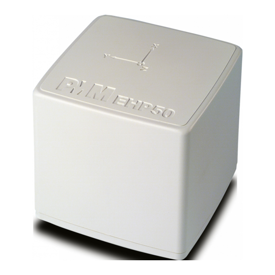
EHP-50G is housed in a small cubic housing. The bottom side panel includes an optic fiber connector, extension rod screw, battery charger connector, ON/OFF button and Status LED. Fig. 1-1 Block diagram of the EHP-50G Analyzer The magnetic sensor system is composed by three magnetic loops positioned orthogonal each other. - Page 11 EHP-50G can be purchased as part of two different sets, for 8053B or 1.3 Configuration and Stand-alone/PC use, which difference consist of the included accessories. Standard Accessories • 8053-SC Soft carrying case, holds basic unit and accessories including 8053-Display; • AC/DC battery charger; •...
-
Page 12: Technical Specifications Of The Ehp-50G
When not differently specified the following specifications are 1.5 EHP-50G Main referred to operating ambient temperature 23°C and relative specifications humidity 50%. Table 1-1 Technical specifications of the EHP-50G Electric and Magnetic Field Analyzer Electric Field Magnetic Field AUX input (MMCX Zin 1kΩ) Frequency range 1 Hz ÷... - Page 13 The uncertainties have been determined according to EA-4/2 [4] and are 1.6 Isotropic E&H field expressed as relative values. analyzer EHP-50G They were estimated as expanded uncertainty obtained multiplying the uncertainty standard by the coverage factor k=1.96, corresponding to a confidence level and anisotropy of about 95%.
- Page 14 a) If we have the certificate with different values of the uncertainty of 1.6.2 Explication Notes calibration, in order to calculate the total expanded uncertainty U the uncertainty of calibration has to be taken into account: where is the standard uncertainty ………….
- Page 15 The total uncertainty derived from typical contributions of linearity, 1.6.3 Measurements anisotropy, the worst case deviation from the nominal weighting filter, Uncertainty of EHP-50G temperature and relative humidity. (Weighted Peak mode) Magnetic probe Total expanded uncertainty % Frequency from 15 Hz to 100 kHz Frequency from 10 Hz to 300 kHz Frequency from 3 Hz to 300 kHz Electric probe...
- Page 16 1.7 Anisotropy 1) The IEEE 1309 [3] defined the anisotropy (A) as the maximum deviation from the geometric mean of the maximum response and minimum response when the probe is rotated around the ortho-axis (e.g. "virtual handle") as shown in the example in figure below. ...
-
Page 17: Ehp-50G Axes
A good evaluation of the anisotropy of a field probe should be carried out in a place where all of the following conditions are satisfied: Far Field Plane wave Uniform field Since the calibration systems are not infinite, these conditions can be approximated but never reached, and so the evaluation of anisotropy for our probes shows results worse than the reality. - Page 18 The geometric structure of the Narda probes, with sensors placed on the peripheral faces of the cube, shows the same behavior as one with the sensors accumulated in the center, when measuring far fields.
-
Page 19: Overload Level Ehp-50G (B Field, Rms)
1.8 Overload level Fig. 1-4 Overload level EHP-50G (B Field, RMS) Fig. 1-5 Overload level EHP-50G (E Field, RMS) General Information 1-11... -
Page 20: Ehp-50G Panel
1.9 EHP-50G Panel Key: 1. Led 2. Battery charger connector 3. ON/OFF button 4. AUX input connector MMCX male type 5. Fiber optic connector Fig. 1-6 Panel of EHP-50G 1-12 General Information... - Page 21 • Temperature < 100% relative without condense • Humidity When the meter needs to be returned to NARDA for repair, please 2.4 To return for repair complete the questionnaire appended to this User’s Manual, filling in all the data that will be useful for the service you have requested.
- Page 22 EHP-50G has an internal rechargeable Li-Ion battery that can be 2.6 Power supply and recharged with the battery charger supplied with it. battery recharging Make a full charging cycle before using the Analyzer for longest battery operation time. ALWAYS connect the battery charger to the power supply BEFORE connecting it to the EHP-50G.
-
Page 23: 8053B
Using the EHP-TS software spectrum analysis can be displayed on a PC 2.7 EHP-50G connected Please refer to chapter 5 of this manual for software instructions. to a PC The EHP-50G offers a Stand-alone mode of operation and thanks to its 2.8 EHP-50G stand alone internal memory is possible to perform a long term acquisition without Mode... - Page 24 To avoid disturbing the measurements in progress, the user or other 2.11 Avoiding persons or mobile vehicles should stay at least 5 meters away from the measurement errors Analyzers. We also recommend that the probe be set up a long way from metal objects or masses.
-
Page 25: Ehp-Ts Installation
EHP50-TS software does not work with EHP50A/B. The EHP-50G requires an EHP50-TS software version 1.61, included in the EHP-TS software setup version 1.64 or later. The new releases can be downloaded directly from the narda website. http://www.narda-sts.it Document EHP50GEN-81007-1.71 - © NARDA 2018... - Page 26 Before connecting the EM field analyzer to PC the EHP50-TS software 3.3 Installing EHP50-TS installation should be performed: Software Browse the Software Media and run the file “EHP50-TS Setup.exe”. The User must have administrator privileges to install the EHP-TS software in Windows Vista, Win7, Win8, Win8.1 and Win10; right click on the program .exe file and click on “Run as administrator”...
- Page 27 EHP-TS software...
- Page 28 When asked for, reboot your system to complete installation EHP50-TS software is now installed in your PC, you can remove it, if needed, simply running the “Uninstall EHP50-TS” application (see cap.8). EHP-TS software...
- Page 29 The EHP50-TS section includes three different applications: Dongle Utility: allows to enable the function ordered such Options using the 40 Digit Activation Code received from NARDA Italy. EHP50 – Stand Alone Mode: main task of this program is to set up EHP- 50G for standalone mode.
- Page 30 This chapter describes controls and functions provided by the EHP50-TS 4.2 EHP50-TS application for time domain and spectrum analysis, included in EHP-TS Application software package. To install EHP-50G, connect the supplied fiber optic to the OPTIC LINK connector taking care that the spigot matches the housing. Connect the other end of the fiber optic to the OPTIC LINK connector of the USB-OC or 8053-OC.
- Page 31 Otherwise the program EHP50-TS main window will be shown: Fig.4-1 EHP50-TS Main Window Description: 1 - EHP50-TS software release, (communication port) 2 - Shows unit 3 - Click “?” to display EHP-50G analyzer information 4 – Name and trace of selected Limit 5 - EHP-50G analyzer battery status 6 - Scan activation for each axis (default setting: all axis activated) 7 - Hold When Done: stops acquisition to allow data analysis as soon as...
- Page 32 Mode section allows setting different acquisition modes, including 4.3 Mode section Frequency and Time domais choice, as well as defining Electric, Magnetic field, or both in the same graph, and preferred Unit. Function: measurements are displayed in different acquisition modes: Spectrum: Frequency Domain sweeps are shown;...
-
Page 33: Defining Frequency Band Through The Pc Mouse
4.4 Span section EHP-50G includes an FFT analyzer to show frequency spectrum of measured field. The span section includes the following: Span: select one of the 8 available spans, keeping in mind that beside the EHP-50G minimum operating frequency of 1 Hz, the minimum start frequency of each Span is 1,2% of Span. -
Page 34: Zoom Window
Fig.4-3 Zoom window Also choosing the best scale range 120 dB or 140 dB can be helpful to better distinguish signals and disturbances. Sweep: the two radio buttons in this box allow the user to select the Linear or Logarithmic frequency scale. Logarithmic scale is used to emphathise and clearly display low frequencies even thow high ones are included in the graph. - Page 35 Standard section allows the user to select standard ICNIRP, IEEE, BGV 4.5 Standard and EC limits, already included by the software installation, as well as user’s limits which can be created through the “Make Limit” function provided by this section. Safety Standard: This section can be used to load a default standard limit saved into the memory at the factory.
- Page 36 Type frequency and field strength for each point of the required limit and click save to save it under the program directory. The limit file will be created as a linear interpolation between specified points. When the ICNIRP or IEEE limit is selected, the software automatically calculates the corresponding total integration of the measured signals, and compares the result with the threshold set by the standard, considering whether it is or is not exceeded.
-
Page 37: Data Section
Even if EHP-50G takes measurement over the entire selected span, shown 4.6 Data section results are related to the displayed spectrum only, allowing thus detailed evaluation of user defineable frequency range through the zoom function. Fig.4-4 Data section The gray band on the left side of the graph highlights signals below the minimum start frequency (1,2 % of Span) which are affected by residual 0 Hz peak. - Page 38 Four additional frames, Acquisition, Marker, Save and Waterfall, are included in the Data section: Acquisition: spectrum is displayed in different acquisition modes. Here is the choice between instantaneous reading and Root Mean Squared over a certain period, which is set in the proper box. A Max Hold function is also available.
- Page 39 It is also possible to insert a comment. The user can select the path where the files will be stored. The saved files will be structured as following: Under the selected folder (EHP50-TS in the example) a folder will be created and called like the current year (ex.
- Page 40 Auto save text extract example Round frequency: when this label is ticked, the frequency indication of the Marker is corrected to the closest round value, thus avoiding approximation errors. Waterfall: press Start Waterfall to run the function, or Open Waterfall to load previously saved measurements.
-
Page 41: Waterfall - Graph 2D
In addition to the spectrum view, another representation has been 4.6.1 Waterfall introduced in the software, commonly called Waterfall. The advantage of this view is that the disturbances are shown in a tridimensional plot. Two dimensions are, as usual, frequency and level, and the third is the time. -
Page 42: Waterfall Main Window
When entering the Open Waterfall function a screen similar to the following appears: Fig.4-6 Waterfall Main Window Like during the scan, on the left is the spectrogram of the measurements. The column in the middle, called Events Horizon, reports the Marker with its frequency and level and many parameters of the measurement setup and of the probe used. -
Page 43: Waterfall - Graph 3D
Fig.4-7 Waterfall - Graph 3D In the Graph 3D, one axis (blue) represents Frequency, another the Level (green) and the third the Time (red). So the Frequency can be on the horizontal axis, the Level on the vertical axis and the Time in depth. For this mode, another box, called Movement, will appear. - Page 44 Another option of the Graph 3D, the Time plot, is available when the Marker is active. Tick the Time label to enter this view. A new window pops up and the plot represents the level at the marker frequency versus time. The horizontal axis of the grid is the time and the vertical axis is the field level.
- Page 45 The subsequent spectra are automatically recorded and saved in a single 4.6.1.1 Data recording file *.WF5 localized in the folder Waterfall in the program root, inclusive of all the analyzer settings. The stored files can be recalled when in Data mode or at startup entering the Open Waterfall window.
- Page 46 This unit concerns the appearance of the program. 4.7 Style section Buttons and labels styles can be selected from a Style list Start and End Color buttons allow selection from a color palette Sample Button and Sample Label show the appearance preview Default button to set appearance to the default parameters Trace to set trace colours by means of the colour palette Tick the Disable colored bands box to avoid highlighting the bands for...
- Page 47 4.8 ICNIRP The International Commission on Non-Ionizing Radiation Protection establishes guidelines for limiting EMF exposure that could affect human health. Standard section allows the user to select standard ICNIRP limits, already included by the software installation. When the ICNIRP limit is selected, the software automatically calculates the corresponding total integration of the measured signals, and compares the result with the threshold set by the standard, considering whether it is or is not exceeded.
- Page 48 In the screenshot above it is depicted an example how the software shows the calculation of the ICNIRP value for the Electric Field measurement. In the screenshot above it is depicted an example how the software shows the calculation of the ICNIRP value for the Magnetic Field measurement. The limit cannot be activated when using Dual Mode.
- Page 49 4.9 IEEE One of the purposes of the Institute of Electrical and Electronic Engineers, Inc. ("IEEE") is to establish exposure standards. Standard section allows the user to select standard IEEE limits, already included by the software installation. When the IEEE limit is selected, the software automatically calculates the corresponding total integration of the measured signals, and compares the result with the threshold set by the standard, considering whether it is or is not exceeded.
- Page 50 In the screenshot above it is depicted an example how the software shows the calculation of the IEEE value for the Electric Field measurement. The limit cannot be activated when using Dual Mode. 4-22 Description...
- Page 51 [Optional] The “Weighted Peak” option is a payment special function implemented in the EHP-50G. Please contact your local Narda distributor for details. The current legislation proposes limits for electromagnetic fields, the value of which depends on the frequency.
- Page 52 4.10.2 EHP50-TS Settings The Standard section allows the user to select one of the standard ICNIRP or EU limits for occupational or general public exposure, already included by the software installation. In the Mode section you can select Electric 1 kV/m or Electric 100 kV/m or Magnetic 100uT or Magnetic 10mT.
- Page 53 Once the Weighted Peak has been enabled, the software shows the result 4.10.3 Weighted Peak of the calculation and its graph over the time. mode Result in percentage over the set hold time The User can set the Hold Time (in milliseconds): The Hold Time is the time resolution of the graph.
- Page 54 The minimum hold time is of 500 milliseconds. The maximum is 10 minutes. The time span of the graph is 200 times the hold time. The rolling measurement memory deletes all values that date back longer than the set time period. The limit selected is shown in the higher right corner of the graph.
- Page 55 The User should make use the following information to choose the proper 4.10.3.1 Dynamic ranges setting for the desired measurement. For every situation, the best choice is to adopt the lower Full Scale available (for example 100 µT) until the meter indicates an over-range warning;...
- Page 56 For convenience, a noise threshold has been established, under which the field indication becomes “LOW”, as in the example below. 4-28 Description...
-
Page 57: Power Density Spectrum
4.11 Additional EHP-200A electromagnetic field analyzer provides Electric and Magnetic functions provided field selective measurement in the 9kHz – 30MHz frequency range. by EHP200-TS Even though there is no difference from EHP-50G regarding minimal physical overall dimensions and sensor positioning, a high frequency selective receiver is housed within this product. -
Page 58: New Wave Impedance Function
New wave impedance function is provided too by selecting the Ohm unit. This function automatically searches and displays result at frequencies showing effective fied ratio calculation. Fig.4-10 New wave impedance function Please refer to EHP-200A user’s manual for detailed informations regarding EHP200-TS application software. -
Page 59: Shorting Loop
SPAN. Lower Spans require longer measurement time. The acquisition can be terminated earlier than 24 hours. Just turn off the EHP-50G and run the application to download the data to the PC. Document EHP50GEN-81007-1.71 - © NARDA 2018 EHP-50G Stand alone mode... - Page 60 5.2 EHP-50G Data Once the data has been collected by the EHP-50G, you should connect it to the PC to download all measurement results. Logger Run “EHP50 - Stan Alone mode” application 5.2.1 Run EHP50 - Stand Alone mode software During the communication process for searching the analyzer EHP-50G, the following messages will appear in sequence for a few seconds: To define measurement parameters for a new stand alone acquisition you...
- Page 61 It is possible to set the date & clock inside the EHP-50G by transferring the actual date & time of your PC. Pushing the button Set Date & Clock you will get the following window: Answering YES, the date & time of your PC will be transferred inside the analyzer.
- Page 62 If the checkbox Include Time is activated, the absolute time will be shown togher with the collected data If the checkbox Include Id is activated, a number representing the position of the data inside the EHP-50G memory will be shown, like in the following example Push the button Download to transfer all data from the analyzer to the PC...
- Page 63 When the communication between the PC and the analyzer has been 5.2.2 Use EHP-50G Logger established, push the button Download to transfer all data from the analyzer to the PC. To use such data you must save them into a file. A typical display will be: On the right side of the display, the software shows: - Serial number of EHP-50G...
- Page 64 This page has been left blank intentionally EHP-50G Stand alone mode...
-
Page 65: Ehp-50G Upgrading Utility Main Window
Main window displayed after the updating program EHP-50F Update Firmware has been run: Fig.6-1 EHP-50G Upgrading Utility Main Window Select USB or RS232 communication port. Before selecting RS232 port, choose the COM port used. Document EHP50GEN-81007-1.71 - © NARDA 2018 Update Firmware... - Page 66 In case the software doesn’t detect any EHP-50G in the USB port, the following message will be displayed. As soon as the connection is established, a message informs to turn the EHP-50G OFF and turn it ON again; press OK to confirm. Two firmware components can be updated by this application: Firmware, which is the main analyzer internal program, and FPGA, to update parameters of the analyzer Field Programmable Gate Array.
- Page 67 Subsequently, when the meter is switched on again, the new version will be displayed in the NBM-550, EHP50-TS or EHP-50 Stand Alone Mode application software. To obtain firmware or FPGA or programs updates for EHP-50G, please contact your NARDA distributor or download it directly from the NARDA Web site: www.narda-sts.it Update Firmware...
-
Page 68: Ehp-50G Options Activation Utility Main Window
6.4 Dongle Utility The Dongle Utility allows to enable the function ordered such Options using the 40 Digit Activation Code received from NARDA Italy. Turn on the EHP-50G and connect it to a free USB or RS232 port of the PC. - Page 69 The program will display the following window: Copy and paste the 40 Digit Activation Code to the “Dongle Code” input field and press the button below related to the specific Option: In case of failure, an error message is showed instead. It will be shown the following message;...
- Page 70 This page has been intentionally left blank Firmware Update...
-
Page 71: Uninstalling Ehp-Ts
Fig. 7-1 Uninstalling EHP-TS Before removing any shared system file, the uninstaller will ask for a confirmation. Answer “NO” in case you are not sure whether the showed system file is required for other applications. Document EHP50GEN-81007-1.71 - © NARDA 2018 Uninstalling Software... - Page 72 EHP50-TS software is now removed from the system, click “Finish” to close uninstaller utility Uninstalling Software...
-
Page 73: Uninstalling Usb-Oc
The following procedure shows how to remove the driver in Windows XP environment. It may be different depending on the operating system in use. Open the Windows Control Panel. Double click “Application Installation”. Document EHP50GEN-81007-1.71 - © NARDA 2018 Uninstalling USB-OC... - Page 74 From the application list select “FTDI FTD2XX USB Drivers” and click “Change/Remove”. Fig. 8-1 Uninstalling USB-OC Unplug the USB-OC converter, if connected, and click “Continue”. Click “finish” to exit the uninstaller, USB driver is now removed from your system. Uninstalling USB-OC...
- Page 75 • Humidity 9.1.3 Return for repair When the Accessories need to be returned to NARDA for repair, please complete the questionnaire appended to this User’s Manual, filling in all the data that will be useful for the service you have requested.
- Page 76 EHP-50G to perform test to comply to the latest standards (i.e. appendix “Determination of the weighted peak exposure”). Please contact your local Narda distributor for details. The instructions concerning how to operate the WP function can be found in chapter 5 of this manual.
-
Page 77: Usb-Oc Adapter
Either USB-OC or 8053-OC is indispensable for updating the internal firmware of the above-mentioned items via a Personal Computer and the relative update software is available free-of-charge on NARDA’s Web site at: http://narda-sts.it Insert USB-OC in the connector of a free USB port of the PC, connect the 9.2.2 Installation... -
Page 78: Technical Specifications Of The 8053-Oc
• EHP-200A Electric and Magnetic Field Analyzers, 9kHz-30MHz Either 8053-OC or USB-OC is indispensable for updating the internal firmware of the above-mentioned items via a Personal Computer and the relative update software is available free-of-charge on NARDA’s Web site at: http://narda-sts.it 9.3.2 Installation... -
Page 79: Technical Specifications Of The 8053-Oc-Ps
8053-OC-PS Power Supply 9.4.1 Introduction The energy available on the DB9 connector of some PC model could be not sufficient to guarantee a link with 8053-OC. In this case, it is necessary to use 8053-OC-PS between the converter and PC. 8053-OC-PS is an optional accessory of the EHP-50G Analyzer. - Page 80 Timer Logging • Post-averaging for logged data on PC (RMS, Mean, Median) For more information please refer to the 8053B product information on the Narda website. Fig. 9-4 8053B Fig. 9-5 8053 Logger Interface software supports evaluation and documentation of results that have been saved on 8053B...
-
Page 81: Ehp-200A Electric And Magnetic Field Probe
8053 runs the latest internal firmware revision. The release should be the 3.16 or higher. To obtain firmware or programs updates for 8053 DISPLAY and EHP-50G, please contact your NARDA distributor or download it directly from the NARDA Web site: www.narda-sts.it Accessories... - Page 82 Recharge time External power supply DC, 10 - 15 V, I = about 500 mA Interfaces RS232 (calibration and firmware update) Upgrade available via Internet at the Web site: http://www.narda-sts.it Software/Firmware Automatic during switch-on of all functions; Autotest Calibration Inside the built-in E²PROM of the probe...
- Page 83 Beside EHP-50G, many other probes are available for using with 8053 9.5.5 Field probes DISPLAY, as for an example the powerful EHP-200A. TABLE 9-5 EHP-200A Electric and Magnetic Field Probe – Analyzer, main characteristics. Level range Frequency range Field Probes Electric field Magnetic field Electric and Magnetic...
- Page 84 9.5.6 Front Key: panel 1. Display 2. Fiber optic Input/Output for additional probes, USB or RS232 interface via fiber optic link 3. RS232 interface 4. Battery charger input, from 10 to 15V DC, 500 mA 5. Securing screws to tripod 6.
- Page 85 The battery charger supplied with the meter can work at either 50 Hz or 60 9.5.8 Battery charger Hz with a supply voltage range between 100 and 240 Volt. It is supplied with different connectors to the supply mains in accordance with the various national standards.
-
Page 86: Tr-02A Tripod
TR-02A Tripod Optional accessory TR-02A tripod allows easy positioning of EHP-50G 9.6.1 Introduction analyzer for accurate field measurement. The standard ¼” threaded insert, located at the bottom of EHP-50G housing allows mounting the analyzer on the tripod through the provided swivel support. - Page 87 Details of swivel support: • full height: 8 cm • weight: 160 g • load capacity: 10 kg • Threaded insert ¼ “ The adjustable swivel makes mounting and fastening the instrument easy as well as changing the angle in any directions via the locking knob.
-
Page 88: Fiber Glass Telescopic Support
TT-01 Fiber Glass Telescopic Support 9.7.1 Introduction TT-01 is an Optional Accessory of the EHP-50G Analyzer. It allows EHP- 50G Analyzer to be easily supported during field measurements. A standard ¼” threaded insert allows easy mounting of EHP-50G on the telescopic support The design and materials of the TT-01 have been specially selected to prevent... - Page 89 Other Accessories Other Accessories are available on request with the EHP50G, such as: car adapter, 12 V battery charger and Internal AC Plug Adapter. Accessories 9-15...
- Page 90 This page has been left blank intentionally 9-16 Accessories...
- Page 91 Moreover, we are continuously improving our quality, but we know this is a never ending process. We would be glad if our present efforts are pleasing you. Should one of your pieces of NARDA equipment need servicing you can help us serve you more effectively filling out this card and enclosing it with the product.
- Page 92 Suggerimenti / Commenti / Note: Suggestions / Comments / Note:...
Need help?
Do you have a question about the EHP-50-G and is the answer not in the manual?
Questions and answers