Table of Contents
Advertisement
Quick Links
Sales & Support:
NARDA
Via Rimini, 22
Safety
20142 - Milano (MI)
Test
Tel.: +39 02 581881
Solutions
Fax: +39 02 58188273
S.r.l. Socio Unico
User's Manual
MAGNETOMETER
FIELD ANALYZER
From DC up to 1000 Hz
SERIAL NUMBER OF THE INSTRUMENT
You can find the Serial Number on the upper side panel of the instrument.
The Serial Number is in the form: 000XY00000.
The first three digits and the two letters are the Serial Number prefix, the last five
digits are the Serial Number suffix. The prefix is the same for identical instruments,
it changes only when a configuration change is made to the instrument.
The suffix is different for each instrument
Document HP01EN-20109-1.05 – Copyright © NARDA 2022
Manufacturing Plant:
Via Benessea, 29/B
17035 - Cisano sul Neva (SV)
Tel.: +39 0182 58641
Fax: +39 0182 586400
HP-01
Advertisement
Table of Contents

Related Manuals for NARDA HP-01


Summary of Contents for NARDA HP-01
- Page 1 Serial Number suffix. The prefix is the same for identical instruments, it changes only when a configuration change is made to the instrument. The suffix is different for each instrument Document HP01EN-20109-1.05 – Copyright © NARDA 2022...
- Page 2 NOTE: ® Names and Logo are registered trademarks of Narda Safety Test Solutions GmbH – Trade names are trademarks of the owners. If the instrument is used in any other way than as described in this User’s Manual, it may become unsafe.
- Page 3 2.4 To return for repair…..…........……...……………… 2.5 To clean the meter…….…..…….…....……...……………… 2.6 HP-01 Led status………………………………………………………. 2.7 Power supply and battery recharging………………………..... 2.8 Battery management…………….………………………..………….. 2.8 HP-01 connected to a PC………………………………….…………. 2.9 HP-01 with 8053B ……..…….……………………………………….. 2.11 Avoiding measurement errors……………………………………… 3 EHP-TS installation Page 3.1 Introduction…………………………………………………..…………...
- Page 4 8.1.5 Power supply and battery chargers…………………….………… 8.2 USB-OC Optical USB Converter…………………………....8.2.1 Introduction………………………………………………………….. 8.2.2 Installation…………………………………………………..... 9 Communication protocol Page 9.1 Disclaimer……………………………………………………….. 9.2 Protocol …………………………………………………………. 9.3 Leds behaviour …………………………………………………. 9.4 HP-01 COMMANDs……………………………………………. 9.4.1 Query Commands …………………………………………… 9.4.2 Setting COMMANDs…………………………………………. 9-10 9.4.3 Analyzer reply…………………………………………………. 9-12 Contents...
-
Page 5: Table Of Contents
4-25 Export tool………………………………………………… 4-21 4-26 Waterfall: 3D Graph……………………………………… 4-21 Update software icons ………………………………….. HP-01 Upgrading utility main window ..……....Switch HP-01 on …..…………………………………….. Update firmware …..…………………………….………. Update firmware button ..……………………….………. Error message …..…………………………….…………. Progressive bar ………………………………………….. Flashing terminated …………………………………….. Uninstall icon .……………………………………………. - Page 6 • To prevent the possible danger of electrocution, do not remove any covers, panels or guards installed on the device, and refer only to NARDA Service Centers if maintenance should be necessary; • To maintain adequate protection from fire hazards, replace fuses only with others of the same type and rating;...
- Page 7 Descrizione MAGNETOMETRO – ANALIZZATORE DI CAMPO Description MAGNETOMETER – FIELD ANALYZER Modello HP-01 Model è conforme ai requisiti essenziali delle seguenti Direttive: conforms with the essential requirements of the following Directives: Bassa Tensione 2014/35/EU Low Voltage Compatibiltà...
- Page 8 This page has been intentionally left blank VIII Safety Consideration...
- Page 9 This section provides a general overview of HP-01 Magnetometer - Field Analyzer. HP-01 is a magnetic DC and low frequency isotropic field probe-analyzer. It provides an advanced technology solution for field analysis in the DC to 1 kHz frequency range in an extremely high dynamic range. It includes X, Y and Z axes simultaneous measurements with a powerful, built in, spectrum analyzer.
-
Page 10: Sensor Position
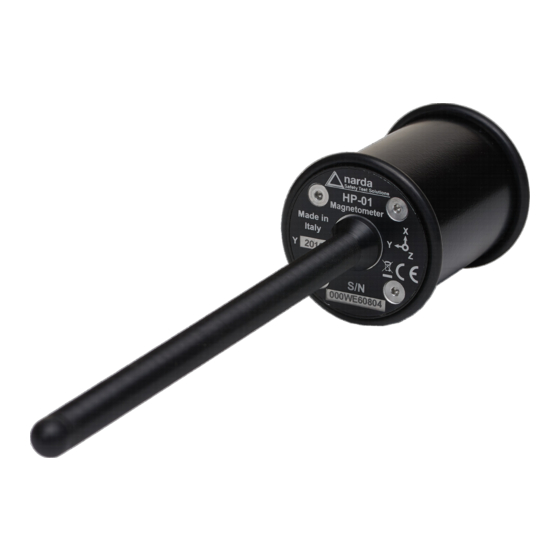
The notch near the end of the tip marks the sensor position. The orientation of the three axis is depicted onto the top panel. Fig. 1-1 Sensor position General Information... - Page 11 1.3 Configuration and The HP-01 Set for NBM-550 and PC use, includes the following items: Standard Accessories • HP-01 Basic Unit; • Zero-Gauss Chamber; • AC/DC Converter with plug adapters; • Cable, FO Duplex, RP-02, 10 m; • USB-OC Optical Converter;...
-
Page 12: Technical Specifications Of The Hp-01
When not differently specified the following specifications are referred to an operating ambient temperature of 23°C and relative humidity 50%. specifications Table 1-1 Technical specifications of the HP-01 Magnetometer - Field Analyzer Frequency range DC ÷ 1000 Hz Measurement range 10 µT ÷... - Page 13 1.6 HP-01 Panel Key: 1. Power-on LED 2. Battery charger connector 3. ON/OFF button 4. Fiber optic connector 5. Data LED Fig. 1-2 Panel of HP-01 General Information...
- Page 14 This page has been intentionally left blank General Information...
- Page 15 < 100% relative without condense 2.4 To return for repair When the meter needs to be returned to NARDA for repair, please complete the questionnaire appended to this User’s Manual, filling in all the data that will be useful for the service you have requested.
- Page 16 When the recharge is complete, this is indicated by the Led of the HP- 01, with a rapidly blinking Green light. If the battery charger is plugged in to the HP-01 while the software is running, the analyzer will stop the measurements.
- Page 17 Switch the unit on with a short key press of the Power button to set the probe for communication with HP-TS pc software. 2.10 HP-01 with HP-01 is linked to 8053B via the fiber optic link. 8053B Switch the unit on with a short key press of the Power button, wait 2 seconds and press the key a second time until the ON LED lights up to set the probe for communication with 8053B.
- Page 18 This page has been intentionally left blank Installation and use...
-
Page 19: Hp-Ts Installation
3.1 Introduction fibre optic link, of HP family Magnetometers and field analyzers. By means of the USB-OC optical to USB converter, HP-01 can be connected to a PC USB port. If needed, the selected COM port should be assigned to the application software (see cap.5 HP01-TS applications). -
Page 20: Setup Icon
3.3 Installing HP01-TS Before connecting the Magnetic field analyzer to PC the HP01-TS software installation should be performed: Software Double click on the file “HP01-TS Setup.exe” included on Software Media Fig. 3-1 Setup icon The User must have administrator privileges to install the HP01-TS software in Windows 7 or higher;... -
Page 21: Installation Folder
Fig.3-4 Installation folder Fig.3-5 Ready to install HP01-TS software... -
Page 22: Installing Hp01-Ts
Fig.3-6 Installing HP01-TS Fig.3-7 Installation successful When asked for, reboot your system to complete installation Fig.3-8 Reboot HP01-TS software is now installed in your PC, you can remove it, if needed, simply running the “Uninstall HP01-TS” application (see cap.8). HP01-TS software... -
Page 23: Hp01-Ts Icons
The HP01-TS section includes two different applications: HP01-TS: this program is used to perform live Time Domain and Spectrum Analysis measurements when an HP-01 analyzer is connected to PC. HP01UP: this is the tool for internal firmware upgrading. Uninstall HP01-TS: to remove the software package from the PC. -
Page 24: Hp01-Ts Main Window
The program HP01-TS main window will be shown: 4.2 HP-TS Main window Fig.4-3 HP01-TS Main Window Description: 1 - Title bar: see §4.2.1 2 - Acquisition toolbar: see §4.2.2 3 - Preference toolbar: see §4.2.3 4 - Info ? toolbar: see §4.2.4 5 - Displayed measurements: see §4.2.5 6 - Frequency selection: see §4.2.12 7 - Span selection: see §4.2.13... - Page 25 The software release shown here, together with the PC port in use to 4.2.1 Title bar connect the HP-01. The control buttons allow to minimize to icon, enlarge/restore the main window and exit the program: When minimizing the main window the information is displayed in the Windows application bar at the bottom of screen.
-
Page 26: Averaging
To set Averaging and to activate the Max Hold function. 4.2.2 Acquisition toolbar 4.2.2.1 Averaging This function can be used to select the proper averaging for the displayed level. The number, between 1 (OFF) and 64, corresponds to the quantity of measurements participating in the calculation of the mean value. -
Page 27: Settings
4.2.3 Preference toolbar It includes Settings, Minimized UI, Measurements log and Languages selection. 4.2.3.1 Settings This section concerns the appearance of the program. Fig.4-5 Settings Display, Plot, Plot/Spectrum, Spectrogram/Waterfall boxes allow selecting each environment parameters and color palette. Default button to set appearance to the default parameters Press Save button to store the specific choice. - Page 28 4.2.3.3 Measurements log Click on it to enable the function Measurements Log to display the Save Meas button in the main window. The symbol √ means that the function is activated. See § 4.2.4.3.1 Save Meas button for further information. Every time the software starts, the function Measurements Log is disabled.
-
Page 29: Info Toolbar
The Info (?) toolbar allows the User to visualize the data of the probe, such 4.2.4 Info ? toolbar as internal firmware release, Serial Number, current Battery Voltage and last Calibration Date. 4.2.4.1 Release 4.2.4.2 Serial Number 4.2.4.3 Battery Voltage 4.2.4.4 Calibration Date - About: Manufacturer information. - Page 30 Battery voltages below 3.59V (5% of charge) are displayed red. If the battery charger is plugged in to the HP-01 while the software is running, the analyzer will stop the measurements. - Temperature in degrees Celsius...
-
Page 31: Total And Xyz Display
Mode button allows activating X, Y, Z axis levels indication or not. 4.2.6 TOT / XYZ In any case, the total value is always shown. Mode button Fig.4-8 Total and XYZ display 4.2.7 Save Meas button Active Measurements Log (√) to display the Save Meas button in the main window. - Page 32 For every working session (from starting to closing the software) a headline is created in the text file with data probe, software settings and field values: Every time the button Save Meas is selected, new values are saved in the corresponding headline.
-
Page 33: Zero Gauss Chamber
Press Stop to momentary suspend the samples acquisition. Press again to 4.2.8 Stop / Run button resume The button XYZ/TOT is active even when in Stop mode. If the program is exit when in Stop mode, it will restart in Run mode. Zeroing is used for offset correction in order to optimize the sensitivity for 4.2.9 Zero button low static fields. - Page 34 4.2.10 Exit button Press EXIT to end the program. The current settings are saved and will be recalled at the next start. The following message will appear: Press YES to close the software (the HP01-TS will remain on). Press NO to continue using the software 4.2.11 Sample status The Sample status will provide the following information: Blinking green square shows valid acquisition...
- Page 35 4.2.12 Frequency selection It includes DC, Single Frequency or Wide Band selection with parameters In DC mode (0 – 1 Hz) there is no Span selection available. In Wide Band Mode the displayed measurement result is integrated over frequency from Fstart to Fstop. The user can enter Fstart and Fstop depending on the selected Span.
-
Page 36: Span Selector
This is the box where it is possible to choose one of the four options 4.2.13 Span selection available: Fig.4-12 Span selector No Span selection available when DC mode (0 – 1 Hz) is selected (see §4.2.12) The Resolution Bandwidth RBW (selectivity) of the measurements is depending on the Span setting: Span 20 Hz... -
Page 37: Plot Graph
The Plot function is a time domain graph of the measured level. 4.3 Plot mode Fig.4-14 Plot graph The Total field is always traced, while the X,Y and Z axis traces are shown only when activated in the main window. The marker can be activated for one of the X, Y, Z and T (Total) traces. -
Page 38: Scale Selector
This control is used to select the full-scale of the level axis. 4.3.3 Scale Fig.4-15 Scale selector 4.3.4 Save File All collected measurements can be saved in a text file using this function. To enable the “Settings” and “Save” buttons it is necessary to stop acquisition by clicking the “Hold”... -
Page 39: Spectrum Graph
4.4 Spectrum mode field. The Spectrum section includes the following: Span: select one of the 4 available spans, keeping in mind that the HP-01 minimum operating frequency is DC and maximum stop frequency is about equal to the span itself. -
Page 40: Span Selection
A second marker can be also enabled. In this way the two values are shown (Marker 1 and Marker 2) and also the difference between them (Delta Markers) is displayed. The desired Span can be selected among four choices available, as depicted below. -
Page 41: Waterfall Screen
In addition to the spectrum view, another representation has been 4.5 Waterfall mode introduced in the software, commonly called Waterfall. The advantage of this view is that the disturbances are shown with different colors depending on their strength. This helps evaluate level variations over time and to easily investigate sporadic signals. -
Page 42: Waterfall: 2D Graph
In the Graph 2D, the horizontal axis represents Frequency, the vertical axis is the Time and the color is the Level. The signal amplitude is represented in a scale of arbitrary colors, usually the darker the lower and the brighter the higher, like in thermography. The Color Scale referenced to levels and units, is indicated on the left bar on the screen. -
Page 43: Export Tool
Fig.4-25 Export tool The Export tool allows the User to save the screen snapshot. In the Graph 3D, one axis (horizontal) represents Frequency, another the Level (vertical) and the third the Time (depth). For this mode, the marker can be placed by a left click of the mouse over any point of the signals, while the graph aspect can be changed as desired by clicking the right button and dragging the mouse in a simple and intuitive way. - Page 44 This page has been intentionally left blank 4-22 Description...
-
Page 45: Update Software Icons
This section provides all the information required for firmware updating. The Update Firmware Program is available after HP-TS package installation. Turn off the HP-01 and connect it to a free USB port of the PC. 5.2 To run the Run HP-01 Update Firmware to start the update program. -
Page 46: Switch Hp-01 On
The User should check that the battery level is at least 3.9 V before starting the upgrade. Fig.5-3 Switch HP-01 on As soon as the connection is established, a message informs to turn the HP- 01 OFF and turn it ON again; press OK to confirm. -
Page 47: Error Message
At the end, a message informs if the update has been successfully performed. Fig.5-8 Flashing terminated Turn the HP-01 OFF (it could seem to be already OFF but it is not) and turn it ON again. The HP-01 is now updated with the new version of the internal firmware. - Page 48 This page has been intentionally left blank Firmware Update...
-
Page 49: Uninstall Icon
It is possible to remove the HP-TS software from the PC according to the 6.1 Uninstalling following procedure: HP-TS Software Run the Uninstall HP01-TS utility. Fig.6-1 Uninstall icon Follow the uninstaller instructions. Fig. 6-2 Uninstalling HP01-TS Document HP01EN-20109-1.05 - © NARDA 2022 Uninstalling Software... -
Page 50: File Remove Confirmation Request
Before removing any shared system file, the uninstaller will ask for a confirmation. Answer “NO” in case you are not sure whether the showed system file is required for other applications. Fig.6-3 File remove confirmation request Fig.6-4 Uninstallation successful HP01-TS software is now removed from the system, click “Finish” to close uninstaller utility Uninstalling Software... -
Page 51: Uninstall Driver Program
7 or higher environment. Click Control Panel Programs and Features. Look for the “PL-2303 USB- to-Serial” program and click the Uninstall button. Fig.7-1 Uninstall driver program Select Remove and click Next button to continue. Document HP01EN-20109-1.05 - © NARDA 2022 Uninstalling USB-OC... - Page 52 Click Yes to confirm. Click “finish” to exit the uninstaller; USB driver is now removed from your system. Uninstalling USB-OC...
- Page 53 Battery Charger) • Humidity < 95% relative When the Accessories need to be returned to NARDA for repair, please 8.1.3 Return for repair complete the questionnaire appended to this User’s Manual, filling in all the data that will be useful for the service you have requested.
- Page 54 HP-01 accessories are powered by either internal rechargeable batteries or 8.1.5 Power supply and directly from other devices which they are connected to. battery chargers The AC/DC battery charger can be used with a power frequency at either 50 Hz or 60 Hz with a supply voltage between 100 and 240 AC Volt.
-
Page 55: Usb-Oc Adapter
USB-OC Optical USB Converter USB-OC is standard accessory of the HP-01 Analyzer. 8.2.1 Introduction It converts the signals of some of the system’s accessories, which are only connected via fiber optic, into USB-compatible signals. It, therefore, makes it possible to link the following items up to the USB port of any Personal... - Page 56 This page has been intentionally left blank Accessories...
- Page 57 Narda’s communication protocol into User’s or third party software is entirely at the User’s risks and responsibility. In no way Narda STS s.r.l shall be liable for damages of any kind consequent to the use of the information provided in this chapter.
- Page 58 Right after HP-01 switched on, DATA LED remains RED for 500ms. Then it starts blinking. The on and off periods depend on: - Sensor range: The time DATA LED is on is longer when HP-01 is in high range mode than when HP-01 is in low range mode.
- Page 59 In the case of an unrecognized command (available commands are ? and S), HP-01 replies with Command ERROR. Example: #H1&SPA* Reply: Command ERROR In the case of a wrong command field, HP-01 replies with the received command followed by ERROR string. Example: #H1?SIPA* Reply: SIPA ERROR.
- Page 60 Query commands ask the instrument about a specific status; it responds 9.4.1 Query Commands back with a message containing the requested information. Query commands contain a ? character in the command string. Command Description Example Battery voltage query command. Example: #H1?BAT* ?BAT The reply gives back the voltage in V of Reply: 3.99...
- Page 61 Wide band field query command (channel Example: #H1?FLPX 10.3,110* ?FLPa fs,fe power). The command can specify the Reply: FLP 1.349;mT;9.00,111.00;X axis on which the field has to be evaluated (T for total field value). When Example: #H1?FLP 3,120.0* no axis is indicated field values for X, Y, Z Reply: axis fields and T field are returned.
- Page 62 Field value query command. Example: #H1?FLSX 13.1* ?FLSa f Reply: FLS 0.10;mT;12.00;X command can specify the axis on which the field has to be evaluated (T for total Example: #H1?FLST 12.2* field value). When no axis is indicated Reply: FLS 1.03;mT;12.2;T field values for X, Y, Z axis fields and T field are returned.
- Page 63 Wide band field query command. The Example: #H1?FLWX 12.3,100.2* ?FLWa Reply: command can specify the axis on which fs,fe FLW 1.03;mT; 12.00,99.00;X the field has to be evaluated (T for total field value). When no axis is indicated Example: #H1?FLWT 12.3,100.2* field values for X, Y, Z axis fields and T Reply: field are returned.
- Page 64 + means an over-range has occurred Identifier query. Example: #H1?IDN* ?IDN The answer displays the name of the Reply: IDN=HP-01 Narda; machine, its serial number; the firmware S/N:000AA00000; FW:A.50 06/16; version and date, and the calibration date. Cal:21.06.16 Peak's amplitude and frequency on axis a.
- Page 65 Flag availability query command. The Example: #H1?RDF* ?RDF reply format: Reply: RDF=8 RDF=0+0x1(x_rdy)+0x2(y_rdy)+0x4(z_rd Spectrum ready (0b1000) y)+0x08(spectr_rdy) First 3 least-significant bits refer to new Example: #H1?RDF* data availability (new data since last FLD Reply: RDF=4 or FLS or FLW or GDC queries are z-data ready (0b0100) available).
- Page 66 Setting commands set the instrument; it responds back with a message 9.4.2 Setting COMMANDs containing the set parameter. Setting commands contain a S character in the command string. Command Description Example Span mode setting command. Example: #H1SSPA1* SSPA The command must be in the format SPA Reply: SPA=1 The reply is in the format: SPA=x where:...
- Page 67 DCE mode setting command. Example: #H1SDCE 0* SDCE The command must be in the format DCE Reply: DCE=0 The reply is in the format: DCE=x Example: #H1SDCE 1* where: Reply: DCE=1 x can be 0: No DCE mode, standard FFT mode Example: #H1SDCE 2* 1: DCE mode Reply:...
- Page 68 Typically, the User should first send the HP-01 all the setting commands to insure the analyzer is correctly set with the wanted parameters, and then ask for the spectrum and read the reply.
- Page 69 Spectrum Bytes Mnemonic Type Description Position 1st bin lev Uint Level to be multiplied by scaleFact X 2nd bin lev Uint …. … … Uint …. 32+2*bins Last Bin Lev Uint …. Spectrum 2+32+2*Bins 1st bin lev Uint Level to be multiplied by scaleFact Y 4+32+2*Bins 2nd bin lev Uint...
- Page 70 This page has been intentionally left blank 9-14 Communication protocol...
- Page 71 Moreover, we are continuously improving our quality, but we know this is a never ending process. We would be glad if our present efforts are pleasing you. Should one of your pieces of NARDA equipment need servicing you can help us serve you more effectively filling out this card and enclosing it with the product.
- Page 72 Suggerimenti / Commenti / Note: Suggestions / Comments / Note:...
Need help?
Do you have a question about the HP-01 and is the answer not in the manual?
Questions and answers