Table of Contents
Advertisement
Quick Links
Manufacturing Plant:
NARDA
Via Benessea, 29/B
Safety
17035 - Cisano sul Neva (SV)
Test
Tel.: +39 0182 58641
Solutions
Fax: +39 0182 586400
S.r.l. Socio Unico
SMARTS AMC
AREA MONITOR COMPACT
User's Manual
EQUIPMENT SERIAL NUMBER
You can find the Serial Number on the rear panel of the main unit and on the side of
the wall support bracket.
Serial Number is in the form: 0000X00000.
The first four digits and the letter are the Serial Number prefix, the last five digits are
the Serial Number suffix. The prefix is the same for identical instruments, it changes
only when a configuration change is made to the instrument.
The suffix is different for each instrument.
Document SMARTSAMCEN-40505-3.09 – Copyright © NARDA 2024
www.narda-sts.it
nardait.support@narda-sts.it
narda-sts@onlinepec.it
Advertisement
Table of Contents

Related Manuals for NARDA SMARTS AMC


Summary of Contents for NARDA SMARTS AMC
- Page 1 The first four digits and the letter are the Serial Number prefix, the last five digits are the Serial Number suffix. The prefix is the same for identical instruments, it changes only when a configuration change is made to the instrument. The suffix is different for each instrument. Document SMARTSAMCEN-40505-3.09 – Copyright © NARDA 2024...
- Page 2 NOTE: ® Names and Logo are registered trademarks of Narda Safety Test Solutions GmbH – Trade names are trademarks of the owners. If the instrument is used in any other way than as described in this User’s Manual, it may become unsafe.
- Page 3 Contents Safety recommendations and instructions.………......VIII EC Declaration of Conformity SMARTS AMC Area Monitor..1 General information Page 1.1 Documentation…................. 1.2 Introduction……………........….……………… 1.3 Standard accessories ……………..........1.4 Optional accessories..............1.5 Main specifications..............1.6 AMC Main unit……….........………....1.7 AMC Wall support bracket and Interface ………………………..
- Page 4 4-36 4.6.6 Start Log…………………………………….………………………. 4-36 4.6.7 Stop Log…………………………………………………………….. 4-36 4.6.8 Only the first function and Download Log button……………….. 4-37 5 SMARTS AMC Management software instruction Page 5.1 Introduction.………..........…....5.2 Hardware requirements…………………………………………….. 5.3 Installation…......…………………………………… 5.4 AMCManagerPlatform control window…………………………. 6 Update firmware Page 6.1 Update Firmware……………………………………………………...
-
Page 5: 11.7 Tr-02A Tripod
8 LR01 Manager APP Operating instruction Page 8.1 Introduction.………............………. 8.2 Installation……………………..……..……………………..………. 8.3 LR01 Manager Main window………………………………………. 8.3.1 Menu……………………………………………………..………. 8.3.1.1 Settings………………………………………………….………. 8.3.2 Technical data……………………………………………………. 8.3.3 Live Measurements………………………………………………. 8.3.4 Logger and Save measurements………………………………. 8.3.5 Info ………………………………………………………..………. 9 Using of LR-01 with WearOS (Smartwatch) Page 9.1 Introduction……………………………......………. -
Page 6: Table Of Contents
Figures Figure Page Top panel…………………...…….………………….……………… Wall support bracket and AMC Interface (top view)…….……..AMC Interface Connectors detail (bottom view)………………… Programmable User’s Port HD-15 female connector pinout….. User’s Port application example………………………………….. EP-1B-09 Probe…………………………………………………… EP-1B-10 Probe…………………………………………………… EP-1B-11 Probe…………………………………………………… 1-10 EP-1B-12 Probe…………………………………………………… 1-11 1-10 EHP-2B-05 Shaped Probe ……………………………………….. - Page 7 Tables Table Page Main specifications …….……….………………………………… SMARTS AMC Area Monitor Compact Field Probes …………. Visual Led status……………………….………………………….. 2-14 Visual Led status in Loggermode……..………………………….. 2-14 Manual Log Button status..……………………………………... 2-15 Buzzer status..……………………………………………………. 2-15 Accelerometer axes orientation………………………………….. 2-15 10-1 Query commands list …………………………….……………..…...
- Page 8 • To prevent the possible danger of electrocution, do not remove any covers, panels or guards installed on the device, and refer only to NARDA Service Centers if maintenance should be necessary; • To maintain adequate protection from fire hazards, replace fuses only with others of the same type and rating;...
- Page 9 Descrizione STAZIONE DI MONITORAGGIO COMPATTA Description AREA MONITOR COMPACT Modello SMARTS AMC/00 Model è conforme ai requisiti essenziali delle seguenti Direttive: conforms with the essential requirements of the following Directives: Apparecchiature Radio Compatibiltà Elettromagnetica...
- Page 10 This page has been left blank intentionally Safety considerations...
- Page 11 1 – General information The following documents are included in this Manual: 1.1 Documentation • A questionnaire to be sent to NARDA together with the apparatus should service be required. • A checklist of the accessories included in the shipment.
- Page 12 The Area Monitor Compact can be installed wall mounted by bracket or suitable for ground installation with the provided Tripod AMC support and the option TR-02A or upside-down if ceiling mounted (see Chapter 2). General information...
- Page 13 1.3 Standard Standard accessories included with AMC Area Monitor Compact: • Main unit accessories • USB Cable – USB(A)/USB(C), 2 m long • AC/DC Converter with plug adapters • Cable, FO Duplex, RP-02/10, 10 m long • USB-OC Optical Converter •...
-
Page 14: Main Specifications
1.5 Main When not differently specified, the following specifications refers to an operating ambient temperature of 23°C and relative humidity of 50%. specifications Table 1-1 Technical specifications Optical (RP-02), USB-C, WiFi (802.11 b/g/n), Bluetooth (5.0), Ethernet Interfaces 10/100 BaseT (PoE), User’s Port Serial Optical Interface 115200 Baud Optical fiber connection RP02 connector up to 40 m (USB-OC) -
Page 15: Top Panel
1.6 AMC Main unit Legend: 1. Robust bayonet connector 2. GPS antenna 3. Wireless antennas 4. Visual Led (see §2.7) 5. Manual log button Fig. 1-1 Top panel 1.7 AMC Wall support bracket and Interface Legend: 1. AMC Interface 2. Wall bracket 3. -
Page 16: Programmable User's Port Hd-15 Female Connector Pinout
1.7.1 DB-15 User’s Port The SMARTS AMC Area Monitor Compact is also equipped with DB-15 (HD-15) connector for the Programmable User’s Port. and application example Fig. 1-4 Programmable User’s Port HD-15 female connector pinout 1 GND +5 Volt power out 11 OUT2 Emitter 2 OUT4 N.C Relay... - Page 17 1.8 Field Probes The following list shows the Field probes designed for SMARTS AMC Area Monitor Compact TABLE 1-2 Technical Specifications of SMARTS Area Monitor Compact Field Probes Field Probe Range of frequency Reading ELECTRIC FIELD PROBE EP-1B-09 100 kHz – 8 GHz 0.2 –...
-
Page 18: Ep-1B-09 Probe
ELECTRIC FIELD PROBE EP-1B-09 Frequency range 0.1 MHz – 8 GHz Level range 0.2 – 200 V/m Overload 600 V/m Linearity +/- 0.5 dB (+/- 0.3 dB typical) Dynamic range > 60 dB Resolution 0.01 V/m Sensitivity 0.2 V/m 0.1 – 0.15 MHz +1.5/-3 dB Frequency flatness (typical) 0.15 –... -
Page 19: Ep-1B-10 Probe
ELECTRIC FIELD PROBE EP-1B-10 Frequency range 0.3 MHz – 40 GHz Level range 0.5 – 800 V/m 1200 V/m Overload Linearity +/- 0.5 dB (+/- 0.3 dB typical) Dynamic range > 64 dB 0.01 V/m Resolution Sensitivity 0.5 V/m 0.3 – 4000 MHz +/- 1.5 dB Frequency flatness (typical) 4 –... -
Page 20: Ep-1B-11 Probe
ELECTRIC FIELD PROBE EP-1B-11 Frequency range 0.1 MHz – 12.5 GHz Level range 0.2 – 200 V/m Overload 600 V/m Linearity +/- 0.5 dB (+/- 0.3 dB typical) > 60 dB Dynamic range Resolution 0.01 V/m Sensitivity 0.2 V/m 0.1 – 0.15 MHz +1.5/-3 dB Frequency flatness (typical) 0.15 –... -
Page 21: Ep-1B-12 Probe
ELECTRIC FIELD PROBE EP-1B-12 Frequency range 0.3 MHz – 18 GHz Level range 0.5 – 800 V/m 1200 V/m Overload Linearity +/- 0.5 dB (+/- 0.3 dB typical) Dynamic range > 64 dB 0.01 V/m Resolution Sensitivity 0.5 V/m 0.3 – 4000 MHz +/- 1.5 dB Frequency flatness (typical) 4 –... - Page 22 DUAL-BAND ELECTRIC AND MAGNETIC SHAPED FIELD PROBE EHP-2B-05 For ICNIRP 1998 and SC6 2015 Electric Field Magnetic Field Occupational 0.5 – 9250 MHz ICNIRP 1998 General Public Frequency range 20 – 1000 MHz Controlled 3 – 9250 MHz SC6 2015 Uncontrolled 0.1 –...
- Page 23 DUAL-BAND ELECTRIC AND MAGNETIC SHAPED FIELD PROBE EHP-2B-06 For ICNIRP 1998 and SC6 2015 Electric Field Magnetic Field Occupational ICNIRP 1998 0.5 MHz – 60 GHz General Public Frequency range 20 – 1000 MHz Controlled SC6 2015 3 MHz – 60 GHz Uncontrolled Occupational / Controlled 0.1 –...
- Page 24 DUAL-BAND ELECTRIC AND MAGNETIC SHAPED FIELD PROBE EHP-2B-07 For ICNIRP 2020 and FCC 96-326* Electric Field Magnetic Field Occupational ICNIRP 2020 5 – 9250 MHz 1 – 1000 MHz General Public Frequency range Occupational 2 – 9250 MHz 2 – 1000 MHz FCC 96-326 General Pop.
- Page 25 DUAL-BAND ELECTRIC AND MAGNETIC SHAPED FIELD PROBE EHP-2B-08 For ICNIRP 2020 and FCC 96-326* Electric Field Magnetic Field Occupational ICNIRP 2020 5 MHz – 60 GHz 1 – 1000 MHz General Public Frequency range Occupational 2 MHz – 60 GHz 2 –...
- Page 26 This page has been left blank intentionally 1-16 General information...
- Page 27 Battery Charger) • Humidity < 95% relative When the Area Monitor Compact needs to be returned to NARDA for 2.4 Return for repair repair, please complete the questionnaire appended to this User’s Manual, filling in all the data that will be useful for the service you have requested.
- Page 28 For further information about the use of AMC with Probes Manager software, please refer to the chapter 3, 4 and 6. For further information about the use of AMC with SMARTS AMC Management software, please refer to the chapter 5 .
- Page 29 2.6.1 Wall mounted Follow the instructions below: Installation - Fix the provided three expansion plugs to the wall; for a correct installation refers to the following hole diameter and distance: - Assembly the Wall support bracket to the AMC Interface with 2 pcs. socket head cup screws M4x20mm and washers using Allen key 3mm Installation and use...
- Page 30 - Install the bracket to the wall and tight the provided 3 pcs. screws 4.5x40mm. - Turn off the Main unit and plug it into the USB-C connector located on the top of the AMC interface. Fix the Main unit to the base plate with the provided screws 1/4”x5/8 - Connect the probe to the Main unit upper round multipole connector paying attention to the position key and tightening the bayonet joint.
- Page 31 10 m. The DB15 and Ethernet cables are optional accessory. Please contact your local Narda distributor for details. - Install the protective cover to the AMC baseplate and tight the 3 pcs.
-
Page 32: Amc - Wall Mounted
- Switch the unit on by pushing the button for a short while and check the Visual Led status (see §2.7) Pressing the button for more than 4 seconds forces the SMARTS AMC to shut down if it is not supplied by USB-C cable or PoE Injector. - Page 33 2.6.2 Tripod mounted - Install the TR-02A Tripod (optional) on the site to be monitored. installation - Turn off the Main unit and plug it into the USB-C connector located on the top of the AMC interface. Fix the Main unit to the base plate with the provided screws 1/4”x5/8 - Assembly the Tripod AMC support to the AMC Interface with 2 pcs.
- Page 34 Please, always use the supplied USB cables and chargers. The DB15 and Ethernet cables are optional accessory. Please contact your local Narda distributor for details. It is advisable to use the Fiber Optic connection to prevent the AMC from affecting the measurement.
-
Page 35: Amc On Tr-02A
- Switch the unit on by pushing the button for a short while and check the Visual Led status (see §2.7) Pressing the button for more than 4 seconds forces the SMARTS AMC to shut down if it is not supplied by USB-C cable or PoE Injector. -
Page 36: Amc On Ceiling By Bracket
For additional information refer to paragraph 2.6.1 2.6.3 Ceiling mounted installation by Bracket Fig. 2-3 AMC on ceiling by Bracket - Fix the expansion plugs 6x30 to the ceiling (refers to the following hole 2.6.4 Ceiling mounted diameter) installation by Tripod AMC - Install the Tripod AMC support to the ceiling and tight the screw 4.5x40mm. -
Page 37: Amc In A Multi-Probe Configuration
2.6.5 Example of installation Fig. 2-5 AMC in a multi-probe configuration Fig. 2-6 AMC link with Wi-Fi communication Installation and use 2-11... -
Page 38: Amc Link With Bluetooth Communication By Smartwatch
Fig. 2-7 AMC link with Bluetooth communication by smartwatch Fig. 2-8 AMC link with Bluetooth communication by mobile device Fig. 2-9 AMC Typical Immunity test irradiation configuration 2-12 Installation and use... -
Page 39: Amc With Power Over Ethernet
2.6.6 Use with Power products is available. It delivers power, data and network connection over Over Ethernet the same cable to the SMARTS AMC Area Monitor Compact through the (optional) Ethernet port available on the bottom of the baseplate (Ethernet cable optional). -
Page 40: 2.7 Visual Led Status
2.7 Visual Led status, Manual log button, Buzzer and Accelerometer TABLE 2-1 Visual Led status LED flashing Description speed color The Visual led begins flashing for VISUAL 30 seconds and The Area Monitor Compact is ready to communicate then blinks every 5 seconds Update firmware or Alarm or Warning threshold exceeded. -
Page 41: Accelerometer Axes Orientation
A manual button allows user to start logging or measurement acquisition or reboot the Area Monitor. Table 2-3 Manual log button status Manual log button Description Logger start with deletion of the previously saved Logs (after Pressing for more than 5 s setting the Logger by means of the AQ_ command). - Page 42 2.8 Power supply and AMC has an internal rechargeable Lithium-ion battery that can be recharged with the USB battery charger supplied with it. battery recharging The AC/DC battery charger can be used with a power frequency at either 50 Hz or 60 Hz with a supply voltage between 100 and 240 AC Volt. International AC plug adapters are provided according to the various national standards and it can be easily removed from the battery charger to be replaced by a different one.
- Page 43 3.1 Introduction This chapter is the installation and operation guide of the PC Software Probes Manager supplied with the SMARTS AMC Area Monitor Compact. The Probes Manager is a software instrument that integrates the SMARTS AMC Area Monitor Compact and allows displaying the measured field level directly on a Personal Computer screen.
- Page 44 Click Next to proceed installing. The installation can be aborted by clicking Cancel button: Probes Manager software installation...
- Page 45 Click Next to confirm the default folder or Change to modify. Click Next to proceed installing. Probes Manager software installation...
- Page 46 The installing status is displayed then: Click Finish to complete and exit the installer. When asked for, reboot your system to complete installation Probes Manager software installation...
- Page 47 The folder Probes Manager is created under Programs\Narda Safety with Probes Manager (see Chapter 4) and LR-01UP (see Chapter 6) executable. Another item is created in the Programs list at Start Menu, which is “Narda Safety”, where the “probes_manager” and “LR-01 Update Firmware” programs must be run from.
- Page 48 This page has been left blank intentionally Probes Manager software installation...
- Page 49 SMARTS AMC Area Monitor Compact. To obtain firmware or program updates for AMC, please contact your NARDA distributor or download it directly from the NARDA Web site http://www.narda-sts.it The software is able to manage the AMC via an optical connection (fiber optic), via a wired connection (i.e.
- Page 50 “USB Serial Port (COMn)”. In Windows 7 and Windows 10 the USB-OC should be automatically installed on your computer. The Narda Probe Manager installation folder also includes the file requested for the driver installation on path \(folder installation)\Driver USB- Serial.
- Page 51 Instead, using the “Auto Search” button the software automatically detects the COM port to which AMC is connected, display the Area Monitor Compact on the list port with its serial number and, in case of using fiber optic connection, enable the Remote On using FO box If the AMC is replaced with other device or viceversa without removing the USB-OC, the Auto Search button must be used to detect the new instrument.
- Page 52 If the WiFi connection has been enabled previously (see §4.2.7.1 Wi-Fi Communications), it will be possible to activate the corresponding communication, if desired, by ticking √ the Wi-Fi box. When the WiFi connection is enable, the Wireless module is placed in “stand-by”...
- Page 53 The Ethernet tool enables the communication between PC and AMC. If Ethernet cable is not properly connected or the parameters are not correct the software returns the following message: When the control window is opened and the stored Firmware version is older than what is available, the software will inform you that an update is needed.
- Page 54 4.2 Probe manager control window Commands description: 1. Title bar 2. Control window buttons 3. Menu: Settings, Preference and ? tags ribbon 4. Main window: Measurements, parameters and technical data 5. Progress bar 6. Correction frequency 7. Reading rate 8. Probe type 9.
- Page 55 Before starting the analysis, some parameters and technical data should be checked as follow: 4.2.1 Languages - Select the desired language under Preferences tab Languages. A confirmation message will be display: Confirm with OK and restart the software with the new language. 4.2.2 Release - Make sure the latest software and setup release are installed on the PC and the latest firmware is stored on AMC.
- Page 56 4.2.5 Calibrations sensor - Set to zero the internal Altimeter reference, calibrate the internal Compass for more location accuracy and synchronized the AMC internal Date&Time to the PC. Click on Settings tab Calibrations sensor. The Altimeter can be useful in applications where the height of 4.2.5.1 Altimeter measurements are relevant, such as, for example, base transceiver station.
- Page 57 4.2.5.2 Compass To improve the AMC location accuracy, the user must calibrate the compass clicking on Compass. While holding the AMC by Radome and following the method shown on screen, move it around different times, tracing a figure eight in the process. The percentage in the upper left part of the main window and the blue bar indicate the progress of the calibration.
- Page 58 4.2.6 Appearance - Customize the Control window, Plot(Graph) and Report file appearance. Different color combinations of the background, text, grid and traces are available under Preferences tab Appearance. This command is also used to set horizontal scale of the graph (Plot Time/Div), save measurements in .TXT or .CSV format (TXT/CSV), define column (Text file separator) and decimal separator (Decimal separator).
- Page 59 4.2.7 Wireless settings - Enable or disable the Wifi or Bluetooth communication on the AMC under Wireless settings tab. To enable the WiFi connection on the AMC: - Connect the PC to the Wi-Fi network you intend to use - Enter the name of the Wi-Fi network (SID) - Enter the password of the Wi-Fi network (Password) - Clicking on OFF, the button toggles to ON for enabling the function 4.2.7.1 Wifi connection...
- Page 60 - The IP address and the Port number will also appear on the main window after a brief Waiting for connection message in red. The WiFi module is placed in “stand-by” condition and, If no action is taken in the last 10 minutes, the wireless connection turns off. Every time the AMC is switched on, the module will return in the same condition since the wireless is set ON in the settings.
- Page 61 4.2.7.2 Bluetooth To enable the Bluetooth (BLE) connection on the AMC: connection - Clicking on OFF, the button toggles to ON for enabling the function. - Confirming with Close The BLE module is placed in “stand-by” condition and, If no action is taken in the last 10 minutes, the Bluetooth connection turns off.
- Page 62 4.2.8 Standard - Load a default standard limit saved into the EHP-2B probe memory at the factory. (for EHP-2B probes only) To enable the limit, mark with √ the corresponding box available on Settings tab Standard. The limit list depends on the EHP-2B model probe connected, as follows: - EHP-2B-05 and EHP-2B-06 Standard limit list: ICNIRP 1998 Occupational;...
- Page 63 4.2.9 Alarms The software provides 7 alarms and for each one of them there is a square in the control window that will show the alarm current status: RED: alarm condition occurred; GREEN: alarm control active. EMPTY: alarm control not active Enable the software to notify alarms by ticking √...
- Page 64 Using DualBand Electric and Magnetic probe, both field value are continuously compared with the Alarm thresholds, set by the user, to determine whether any field alarm condition is occurring. - Alarm S(H) / Alarm H: set the Magnetic field level threshold for Alarm notification - Alarm S(E) / Alarm E: set the Electric field level threshold for Alarm notification...
- Page 65 4.2.10 Averaging Period - Define the average type and the time period on which the averaged field will be calculated during the Logger acquisition (see §4.6 Logger). The result will also be compared with the enabled thresholds. The average can be arithmetic (AVG) or quadratic (RMS). If the value entered is lower than the Time based (Every) set on Logger acquisition mode, a warning message will appear and the nearest correct storing rate will be set by the software.
- Page 66 Once all settings and parameters are set, the software provides: - Display Live measurements on the main window (see §4.3) - Saving Live measurements on the text file (see §4.4) - Display Live measurements in graph way (Plot) (see §4.5) - AMC programmable operation (Logger) (see §4.6) 4.3 Display Live During live measurements the value is displayed with three decimals on the...
- Page 67 Some parameters and technical data are shown in the upper right part of the main window: Description: - Freq: frequency chosen for correction, or OFF when disabled. - Video Averaging: number of the readings on which the RMS average is calculated during Live measurements or OFF when disable - Max Hold: ON when enable, or OFF when disable.
- Page 68 The probe of the AMC can be disconnected and reconnected while in use. The communication will be restarted automatically and the AMC performs a diagnostic test while a progress bar shows the process. Once a link has been established, the live measurements are displayed in the main window again: In case of absence or malfunction of the probe, the message “Probe not connected”...
- Page 69 4.3.1 Sample In the control window the Sample square blinks at the Reading rate set and shows by its color the current status of the data acquisition: RED: data acquisition is still in progress or paused GREEN: data acquired The field value is displayed on the Main window and Plot (Graph) at the 4.3.2 Reading Rate Reading Rate set in seconds.
- Page 70 4.3.3 Correction EHP-2B probe have flatness compensation factors on board that can be applied when the signal source frequency is known, in order to make the Frequency, Correlated measurement even more accurate. To recall the Correction frequency Unit and Show Limits factor (in MHz): graph - Clicking on OFF, the button toggles to ON for enabling the function.
- Page 71 If the frequency correction is enabled but out of range of calibration table stored on probe in use, the indication show the result "---" instead of the value. If the frequency correction is ON and Show Limits graph function is active (√) on Standard menu, the software shows the measurement and limit according to the Standard and Correction Frequency set.
- Page 72 While live measurements are performed, the user can also display the 4.3.4 Video Averaging RMS averaged field using the Video Averaging function. The number of the readings on which the RMS average is calculated is available on the Video Averaging drop-down menu: 4, 8, 16, 32, 64. or OFF when disable.
- Page 73 4.3.5 Max Hold At any time the maximum field strength value can be retained and displayed since the Max Hold has been activated √ on Settings tab. It is therefore updated only if the new value is greater than the previously displayed one showing thus the maximum in the frequency range since the Max hold function was activated While live measurements are performed, the user can freeze the readings...
- Page 74 4.4 Saving Live While the live measurements are performed, the software allows collecting measurements directly in the internal memory of the AMC and saving in a measurements report file using the Auto save txt or Auto save csv function (the format depends on the Text file separator set on Preferences tab ...
- Page 75 Description: Storing Date: working session date. Storing Time: start measurements campaign (hour, minute, second). Device Name: probe type connected to the AMC Device Serial Number: Serial number stored on AMC Frequency: frequency correction in MHz, or OFF when disabled. Video Averaging: (RMS) if enable, OFF if disable Max Hold: ON if enable, OFF if disable Temperature: temperature in degrees Celsius.
- Page 76 Display Live The PLOT function performs Time Domain measurements and showing how the signal level changes over time. measurements The screen displays a continue running graph at the Reading Rate setting. on the graph (PLOT) Once selected the PLOT button, the following graph will appear: Commands description: 1.
- Page 77 Some parameters and technical data are shown in the lower part of the control window (for explanation see Pag.4-19). The Plot and Time/Div setting appear as set on Preferences tab 4.5.1 Settings Appearance. Both can be changed with Settings button in the bottom right corner of the plot;...
- Page 78 4.5.4 Marker For a detailed analysis of the graph, a marker appears on the screen as a colored arrow. In the Marker window the user can select on which trace to place the marker and move it to any point holding the left mouse key down. In the same window is shown the level marked and the instant in which the measurement is made.
- Page 79 If the field level is higher than 110% of the probe maximum nominal level, a red Over Range message will be display on the center top of the graph. In the Marker window is shown Level = Ovr and the instant in which the measurement is made.
- Page 80 4.5.6 Save Press Save button to save the plot as bitmap image or text file (the graph must be paused by clicking Hold button): - Save the graph displayed as a bitmap image (.bmp) for insertion in other applications such as a Word Processor or Image Editor. - Save in text format (.txt) a table containing the data shown since the software is opened or since the graph has been restarted with Reset button.
- Page 81 4.6 Storing AMC is suitable for short-term, medium and, especially, long survey thanks to high capacity internal battery. In Logger acquisition mode it is possible to measurements on the program the Area Monitor Compact for collecting and storing data directly AMC memory in its internal memory.
- Page 82 4.6.2 Logger saving Then, select the Logger saving mode: As above example, when “Threshold triggered” and “Only press button” or “Time base” function is enable, priority is given to the Threshold triggered The internal memory capacity and battery duration are affected by: - the storing Rate (Time Based) - how often the alarm is triggered (Threshold triggered) - How often Manual Log button is pressed (Only press button)
- Page 83 4.6.3 Only press button - Only press button: When active , the acquired field level (instantaneous or averaged) is stored in the AMC internal memory each time the Manual Log button is pressed Pressing the Manual Log button for more than 5s will delete all previous saved data.
- Page 84 4.6.5 Log format Also the Log format can be set: - Compact The file does not contain Acceleration, Speed, Latitude, Longitude, GPS, and Compass information. Each data record is 32 bytes in size and allows storing in the AMC internal memory up to 125k measurements.
- Page 85 4.6.8 Only the first The Download Log button downloads the data stored on AMC internal function and memory to a PC and save them as a text file with a specific name: LOGGER_Probemodel_dd__hh_mm_ss.txt Download Log button If the function Only the first is not enable, the data are download from starting to stopping log data.
- Page 86 - Date: Working session date in dd/mm/yyyy format - Time: Hour, minute, second of the measurement acquisition on electric “S(E)” - S(E) / E-field RMS: shows the RMS average calculated field strength in far field condition Electric ”E” field on electric “S(E)” field - S(E) / E-field peak: shows the peak value measured strength in far field condition Electric ”E”...
- Page 87 In the example below, it is shown the .txt file format In the example below, it is shown the .csv file format Probes Manager operating instructions 4-39...
- Page 88 This page has been left blank intentionally 4-40 Probes Manager operating instructions...
- Page 89 5.1 Introduction SMARTS AMC Management software with the SMARTS AMC Area Monitor Compact. The SMARTS AMC Management software allows user to manage the SMARTS AMC Area Monitor Compact accessible locally (Local Area Network) and wherever located in the world (External network) simultaneously.
- Page 90 Windows server and database services is required for using Cloud based. To install the SMARTS AMC Management software on PC from the 5.3 Installation supplied Software Media as follows. Do not connect the AMC to the PC until the installation is completed.
- Page 91 Click Next to proceed installing. The installation can be aborted by clicking Cancel button: SMARTS AMC Management software...
- Page 92 Click Next to confirm the default folder or Change to modify. Click Next to proceed installing. SMARTS AMC Management software...
- Page 93 The installing status is displayed then: Click Finish to complete and exit the installer. When asked for, reboot your system to complete installation SMARTS AMC Management software...
- Page 94 The folder SMARTSAMCManagement Setup is created under Programs\Narda Safety with SMARTSAMCManagement executable. Another item is created in the Programs list at Start Menu where the “SMARTSAMCManagement Setup” programs must be run from. The AMCManagement icon will be available on desktop.
- Page 95 (Windows 10): Start Programs SMARTSAMCManagement Setup AMCManagement. Commands description: 1. Title bar 2. Control window buttons 3. Local Area Network main window (see §5.1) 4. External Network main window (see §5.1) 5. Info SMARTS AMC Management software...
- Page 96 - Click on Add LR button and enter the IP address assigned for each AMC present on Local Area and External network (Remote). - Once the link has been successfully established, the following main window will appear: - Enter the SMARTS AMC name on the Location column SMARTS AMC Management software...
- Page 97 Descriptions: - Location: SMARTS AMC name - IP: IP address assigned to the AMC and the number of the port. - Identification: AMC Serial Number - Measurement level: The averaged field calculated in order to the average time set - Alarm level: field level threshold for alarm notification...
- Page 98 This page has been left blank intentionally 5-10 SMARTS AMC Management software...
- Page 99 To obtain firmware or program updates for AMC, please contact your NARDA distributor or download it directly from the NARDA Web site http://www.narda-sts.it To update the AMC firmware proceed as follows: - Connect the AMC to PC via Fiber Optic connection (through USB-OC).
- Page 100 This window is displayed. - Pressing the USB-OC button, the LR-01UP utility automatically detects the COM port to which AMC is connected. The User can manually select the COM port assigned to the Area Monitor Compact using the RS232 drop-down menu (the device appears as “USB Serial Port (COMn)”.
- Page 101 - Then switch the AMC on, check the big led status and press OK to continue. - A window is displayed. Click on Update Firmware button to proceed. Once a link has been established, a colored progress bar indicating the process.
- Page 102 This page has been left blank intentionally Firmware Update...
- Page 103 Open the Windows Control Panel. The following procedure shows how to remove the driver in Windows 10 environment. It may be different depending on the operating system in use. Double click “Programs and Features”. Document SMARTSAMCEN-40505-3.09 - NARDA 2024 Uninstalling driver and software...
- Page 104 From the application list select “PL-2303 USB-to-Serial”, click “Uninstall” and follow the instructions. 7.2 Uninstall Narda Press EXIT to quit Narda Probes Manager, disconnect the AMC from the PC and uninstall the software. Probes Manager In Win7 click Windows , NardaProbesManager, then Uninstall Probes_Manager and follow the instructions.
- Page 105 8 – LR01 Manager APP Operating instructions Narda introduces an innovative way to perform the AMC measurements on 8.1 Introduction mobile device by a dedicated App. This section provides the information necessary to use the LR01 Manager application. Download and install the LR01 Manager application on your device from 8.2 Installation...
- Page 106 Once the link has been successfully established, the LR-01 Manager app 8.3 LR01 Manager provides the following features: Main window - Changing AMC settings. - Performing live measurements. - Logging and saving data. These are the basic operations to follow to work with the LR01 Manager.
- Page 107 8.3.1 Menu Commands: - Device: to display the Main window. - Settings: allows to modify the AMC settings. - Save: allows to take a photo of the site monitored and generates an email with attached the last working session log file and the picture. 8.3.1.1 Settings Settings window allows to: - Set the AMC internal clock with the Date and Time of the PC.
- Page 108 In the upper part of the main screen, some technical data are shown. 8.3.2 Technical data - Bat: It shows the residual autonomy during measurements and the achieved autonomy during charging. - Tmp: followed by the temperature in degrees Celsius. - Hum: followed by the percentage of relative humidity.
- Page 109 8.3.3 Live Measurements The mobile device performs live measurements and display the data with all other related information in the LR-01 Manager main window. The screen show the percentage indication of the standard in power density (quadratic scale) calculated on electric “S(E)” and magnetic “S(H)” field strength in far field condition Electric ”E-field”...
- Page 110 8.3.4 Logger and Save In addition to the live measurements, the App allows logging measurements on mobile phone, saving on its internal memory and Measurements sending by email in a simple and reliable way: Click the button in the upper-right main window to start the measurements log.
- Page 111 When the file is saved in .txt format and the table is opened, a huge amount of data are available. For every working session (from starting to closing logging) the following headline will be created in the txt file: - Firmware version and released data (FW 1.21 01/24) - AMC Serial Number (000ZW30304) - Probe connected to the AMC (Probe EHP-2B-07) - Measurement unit (Unit: %)
- Page 112 This page has been left blank intentionally LR-01 Manager operating instructions...
- Page 113 Also make sure turning on the Bluetooth on AMC and Smartwatch. To active the Bluetooth communication on the AMC, the user must connect the Area Monitor Compact to Narda Probe Manager software and enable the BLE function (see §4.2.7.2 Bluetooth connection).
- Page 114 9.3 Operations These are the basic operations to follow to work with the LR01 Manager. All additional information and explanations can be found on chapter 4 9.3.1 Live Measurements Once the link has been successfully established, the Main window is displayed showing the live measurements together with software release.
- Page 115 9.3.2 Technical data Enter on the Technical data panel. Swiping upwards or downwards on the screen, further technical data are shown: - Bat: It shows the residual autonomy during measurements and the achieved autonomy during charging. - Tmp: followed by the temperature in degrees Celsius. - Hum: followed by the percentage of relative humidity.
- Page 116 9.3.3 Settings Enter on the Settings panel. Swiping upwards or downwards on the screen, all settings are shown: - Set the internal digital Filter - Set the AMC internal clock with the Date and Time of the PC - Set to zero the internal Altimeter reference - Calibrate the internal Compass Calibration for more accuracy - Recall the Frequency correction factor (in Hz) stored in the AMC memory or OFF when disabled...
- Page 117 9.4 Close the App On the Apps screen, tap (Recent apps). Use the bezel or swipe left or right on the screen to move to the app to close. Swipe upwards on the app to close it or Tap on Close all to close all running apps.
- Page 118 This page has been left blank intentionally Smartwatch...
- Page 119 10 - Command protocol This chapter provides the information required to control the SMARTS AMC 10.1 Introduction Area Monitor Compact via one of the communication ports (e.g. the fiber optic) connected to a PC and by means of user’s own PC software applications.
- Page 120 If Area Monitor Compact is not supplied by USB-C cable or PoE Injector, the SMARTS AMC automatically turns off 30 minutes after receiving the last command. Please, do not try any commands not covered in this manual, as random poking can cause the system to crash or lose data and calibrations.
-
Page 121: Query Commands List
10.2 List of commands Table 9-1 Query COMMANDs list Syntax Function ?ADR Requests Area Monitor Compact’s address. Requests alarm threshold. ?ALR Requests relative altitude. ?ALT Requests the Area Monitor Compact output status. ?AMC Requests the Area Monitor Compact input status. ?AMS Requests the Area Monitor Compact release and date. -
Page 122: Setting Commands List
Table 10-2 Setting COMMANDs list Syntax Function Sets Area Monitor Compact’s address. SADRa Sets alarm threshold. SALRs Resets the reference altitude. SALT Set the Area Monitor Compact output and alarm(s) SAMCk para SANY Sets the device for alarm notification Sets the logger parameters. SAQ_m;x;t SAVGl;r Selects the averaging time and type... -
Page 123: Query Commands Meaning
Using these commands the AMC can be queried with a series of requests 10.3 Query commands to which the Area Monitor Compact responds. Query commands are characterized by the character ? in the string. TABLE 10-3 Query commands meaning ?ADR This query command #LR?ADR* requests the AMC’s address that represents the additional prefix that can be set by the User to distinguish a specific Area Monitor Compact. - Page 124 This query command #LR?AMS* requests the C4 and C3 input status of the Area Monitor ?AMS Compact. The format is as follows: AMS=C4[OFF/ON]; C3[OFF/ON]; ON|OFF indicates if the related input is triggered or not. Examples of reply with #LR?AMS* AMS:C4=OFF; C3=OFF; <13><10> ?AMV This query command #LR?AMV* requests the Area Monitor Compact release version and date.
- Page 125 This query command #LR?BDR* requests the current Baud Rate of the optical port, where ?BDR the code returned indicates: • 10: 9600 bps • 11: 38400 bps • 12: 57600 bps • else: 115200 bps Example of reply: BDR=3 which means that the optic serial port is set to 115200 bps. ?BLE This query command #LR?BLE* requests the status of the Bluetooth Low Energy module.
- Page 126 This query command #LR?CPS* requests the compass and accelerometer readings. ?CPS The reply is formatted as following: Heading: bearing (orientation); G:x; y; z Bearing is expressed in degrees and orientation as per the compass rose cardinal points. Gravitational acceleration is expressed in hundredths of g (cm/s ) for each of the three axes.
- Page 127 ?GPS This query command #LR?GPS* requests the latest RMC and GGA NMEA phrases (NMEA 0183 ver 3.01) detected by the internal GPS module. RMC NMEA strings are reported in full, starting with $GPRMC and/or $GNRMC, and ending with the checksum followed by CR LF. GGA NMEA strings are reported in full, starting with $GPGGA and/or $GNGGA, and ending with the checksum followed by CR LF.
- Page 128 This query command #LR?LFA* requests the latest average field value. ?LFA[S] The reply provides the value (or values) with current unit, followed by the averaging period in minutes (the same as per AVG command). When a passive probe is installed, the command provides the field levels of the three axes, followed by the total value.
- Page 129 This query command #LR?MES* requests the instantaneous (not averaged) field level. ?MES The reply is the elementary value for each band, in the format: Three-band probe: • MES=W;L;H;V/m; where: • W is the wideband probe field level; • is the low-pass probe field level (e.g. < 862 MHz) •...
- Page 130 This query command #LR?MESS* activates the continued issuing of the instantaneous (not ?MESS averaged) field level. The reply is the elementary value for each band, like ?MES command, but with enabling for the continuous data transfer as soon as they are available, in the format: This command can be useful, for example, to be able to record separately all the elementary data used by the AMC.
- Page 131 ?MESR[v] This query command #LR?MESR* activates the continued issuing of the instantaneous (not averaged) field level with position (GPS) and other sensors (compass, thermometer, hygrometer, barometer, accelerometer) information. The reply is the elementary value for each band, like ?MES command, plus GPS (and sensors) information, with enabling for the continuous data transfer as soon as they are available, in the following format.
- Page 132 Following is the standard NMEA GPRMC and/or GNRMC string that reports the information: • Time (UTC) • Navigation receiver warning A = OK, V = warning • Latitude (deg. min North/South) • Longitude (deg. min East/West) • Speed over ground (Knots) •...
- Page 133 This query command #LR?MSK* requests the alarms Mask. ?MSK The reply provides a string with every armed alarm, with the format: MSK=AWUVPTCawvp SERIAL ALRTRG where the meaning of the symbols is similar to the ?STA command, as follows: • A = Field Level exceeded Alarm; •...
- Page 134 ?PRB This query command #LR?PRB* requests information of the connected probe. The reply provides probe model, latest calibration date, measurement unit, divider in the following format: • Three-band probe: PRB=Name:Dd.Mm.Yy; Unit:Divider:Range:MinLevel:MinFreq:MaxFreq:CorrFreqUnit • Four-band probe: PRB=Name:Dd.Mm.Yy; Unit:Divider:Range:MinLevelWide:MinFreq:MaxFreq:CorrFreqUnit:4:MinLevelSubBand • Single-band probe: PRB=Name:Dd.Mm.Yy; Unit:Divider:Range:MinLevel:MinFreq:MaxFreq:CorrFreqUnit:S •...
- Page 135 This query command #LR?SNS* requests data from the environmental sensor. ?SNS The reply, in the format SNS=T;H;P provides: • T: Temperature, in Celsius degrees (°C) • H: Relative Humidity in percentage (%) • P: Atmospheric Pressure (hPa) Example of reply: SNS=23.9;38.8;1013.6 This query command #LR?SST* requests the level of the signal for the wireless channel.
- Page 136 This query command #LR?STM* requests the active alarms condition. ?STM The reply provides a string showing the active alarms (they must be activated by SMSK command) as following: STA=AWUVPTCawvp • W: Warning level exceeded; • A= ALARM threshold exceeded; • w= end of Warning situation;...
- Page 137 This query command #LR?VST* requests the power supply status. ?VST[V] The reply provides the code as follows: • 0 for battery supply • 1 for external supply connected and battery charge completed • 2 for external supply connected and battery under charging Example of reply: VST=1 which indicates the external 5V supply is connected and the battery is fully charged.
- Page 138 This query command #LR?WMEi* requests the instantaneous % level related to the ?WMEifv (for desired standard. EHP-2B i=1: Reference Standard (same reading as per ?MES command) model i=2: Standard 2 probe only) i=3: Standard 3 i=4: Standard 4 The order of the standards is: - for 01/02/05/06 model: ICNIRP98OCC, ICNIRP98GP, SC6CONTR, SC6UNCONTR.
- Page 139 Adding the “v” character, at the end of the command, so that it becomes ?WMEifv, it is possible to include in the reply string the additional values of heading (degrees), acceleration (g), temperature (° C) and humidity (%) Example of reply: WME=46.47;1930.61;%;*;3.79V; $GPRMC,163230.000,A,4341.1574,N,01047.9386,E,0.01,25.87,190822,,,D*54 ;$GPGGA,163305.992,,,,,0,3,,,M,,M,,*4B ;Heading: 209 (SW);...
-
Page 140: Setting Commands Meaning
These commands are intended for making settings on the AMC. 10.4 Setting commands TABLE 9-4 Setting commands meaning This setting command sets the specific address for the AMC. SADRa It represents the additional prefix that will be accepted and recognized by that specific Area Monitor only, in the same way as the default prefix "LR"... - Page 141 This setting command sets the Logger parameters. SAQ_m;x;t Argument m represents the Logger acquisition mode: I=Instantaneous and M=Average. The Average time and type are settable by SAVG command and the alarm is compared on it. Argument x represents the storing rate in seconds. The minimum value is 1s; the maximum value is 900s in instantaneous mode and it vary according to the AVG or RMS settings (please refer to SAVG command).
- Page 142 This setting command sets the averaging time and type. SAVGl;r • l is the time length in minutes, between 0.25 and 30 with 0.25 minutes resolution up to 1 minute; 1 minute up to 15 minutes and always 30 minutes over 15. •...
- Page 143 This setting command sets the date of the Real Time Clock. SCLDd.m.y Each parameter must be two digits, as following: • d is the day (01 to 31) • m is the month (01 to 12) • y is the year (00 to 99) The reply is the same as per ?CLK command.
- Page 144 This setting command selects the wireless communication channel active at power on, as SDCMc follows: • c=0 to disable all wireless channels at power on; • c=1 to enable Wi-Fi module at power on; • c=2 to enable BLE module at power on. If DCM=1 or DCM=2, the corresponding wireless communication channel will be kept active for 60 seconds.
- Page 145 This setting command switches immediately off the internal GPS module. SGOF The reply GOF=OK indicates that the command has been granted. Example: #LRSGOF* SGOOFF This setting command turns immediately off the AMC. Note: since the Area Monitor goes suddenly off after having received the command, no reply is returned.
- Page 146 This setting command sets the frequency for flatness correction. SKFR f Argument f represents the frequency in Hz at which the correction is to be applied, or 0 whenever it is desired to disable the correction. In the case of an Electric and Magnetic probe, both correction frequencies are set to the indicated value.
- Page 147 This setting command sets the Alarms and Warnings mask. SMSKm The mask must contain the mnemonic symbols that represent the individual alarms as shown in the following table. They can be written in any order. • W = Warning level exceeded; •...
- Page 148 This setting command restores the default configuration. SRST The command resets the main parameters as follows: • All Alarms masked; • Averaging period of 6 minutes; • Running average cleared; • Averaging type: RMS; The reply RST=OK indicates that the command has been granted. Example: #LRSRST* restarts the unit.
- Page 149 This setting command switches the Wi-Fi module to the desired mode. SWFIx The argument x can be as following: • x= ON: turns on the module and starts the connection procedure; • x= OFF: closes any connection and turns off the module, including BLE; •...
- Page 150 10.5 Log file Header The binary file begins with a 128 bytes header, structured as follows: • first 8 bytes are always 0x4C 0x4F 0x47 0x5F 0x53 0x20 0x0D 0x0A [0-7] • 24 bytes reporting the serial number of the AMC (if it is shorter, a zero-padding is performed) [8-31] •...
- Page 151 10.5.1 Log file data All figures in this document are BIG ENDIANNESS. 10.5.1.1 Passive Probes Structure description Tot_avg Tot_Peak Reserved Byte 1 Byte 2 Byte 3 Byte 4 Byte 5 Byte 6 Byte 7 Byte 8 Battery Temp. Alarm PERTS MISC DateTime Byte 10...
- Page 152 10.5.1.3 4-Bands Active Probes Structure description Wide_avg Wide_Peak Reserved Byte 1 Byte 2 Byte 3 Byte 4 Byte 5 Byte 6 Byte 7 Byte 8 Battery Temperature Alarm PERTS MISC DateTime Byte 10 Byte 11 Byte 12 Byte 13 Byte 14 Byte 15 Byte 16 Byte 9...
- Page 153 10.5.2 Field data Field data are represented as 16 bit. Such a figure should be considered as a big-endian unsigned 15 bit integer multiplied by the typical probe divider (see dedicated ?PRB command). In the particular case in which the figure is equal to 0xFFFF then the value must be considered invalid (AMC was not able to get a measure) and all the data (all 32 bytes) are meaningless.
- Page 154 The 16 bit figure named MISC is shown as follows: D07 D06 D05 D04 D03 D02 D01 D00 D07 D06 D05 D04 D03 D02 D01 D00 MISC AVGPerio Byte AVGPeriod Min MONTHS d_Dec 13/14 4 bit unsigned integer 7 bit unsigned integer 2 bit uint This figure ( MISC ) should be considered as four different data as follows: •...
- Page 155 10.5.3 Additional GPS Structure description Validity Acceleration X Acceleration Y Byte 33 Byte 34 Byte 35 Byte 36 Byte 37 Byte 38 Byte 39 Byte 40 Acceleration Z Speed Reserved Byte 41 Byte 42 Byte 43 Byte 44 Byte 45 Byte 46 Byte 47 Byte 48...
- Page 156 10.5.3.1 Position The 16 bit figure named Latitude int is shown as follows: Information Byte Degree Minute 49/50 The figure named Latitude int is made of 4 fields and represents the integer part of the GPS Latitude. • Degree is a 8 bit unsigned integer which indicates the degree of latitude. •...
- Page 157 From -30°C to + 75°C (-20°C to 60°C for Battery Charger) • Humidity < 95% relative When the Accessories need to be returned to NARDA for repair, please 11.4 Return for repair complete the questionnaire appended to this User’s Manual, filling in all the data that will be useful for the service you have requested.
-
Page 158: Usb-Oc Adapters
USB-OC Optical USB Converter 11.6 USB-OC is a standard accessory of the SMARTS AMC Area Monitor 11.6.1 Introduction Compact. It converts the signals of some of the system’s accessories, which are only connected via fiber optic, into USB-compatible signals. It, therefore, makes... -
Page 159: Technical Specifications Of The Tr-02A Tripod
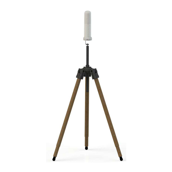
TR-02A Tripod 11.7 11.7.1 Introduction TR-02A is an Optional Accessory of the SMARTS AMC Area Monitor Compact. It allows AMC to be easily supported during field measurements. Each of these instruments has a securing screw, usually placed on the bottom part of its container that enables it to be easily and quickly put into place through the 8053-SN swivel supplied with the tripod. -
Page 160: Amc On The Tr-02A Tripod
Details of the swivel for fastening to the Tripod Joint: • full height: 8 cm • weight: 160 g • load capacity: 10 kg • Threaded insert 1/4“ The adjustable swivel makes mounting and fastening the instrument easy as well as changing the angle in any directions via the locking knob. -
Page 161: Usb Cable - Usb(A)/Usb(C)
11.8 Wall plug regulated switchmode AC/DC power supply is a standard 11.8.1 Introduction accessory of the SMARTS AMC Area Monitor Compact. It is provided with the USB(A)/USB(C) cable to supply the AMC and for charging the internal battery. This is a Class II / Double insulated device for indoor use only. -
Page 162: Tl-Poe150S Front Panel
The Power Over Ethernet, such as TL-POE150S or equivalent products is 11.9.1 Introduction an Optional Accessory of the SMARTS AMC Area Monitor Compact. It delivers power, data and network connection over the same cable to the SMARTS AMC Area Monitor Compact throught the Ethernet port available on the bottom of the AMC baseplate. - Page 163 GPS Not Available If Area Monitor Compact is not supplied by USB-C cable or PoE Injector and the internal battery voltage is low, the SMARTS AMC sends the string: WRN: Low Battery If Area Monitor Compact is not supplied by USB-C cable or PoE Injector and the internal battery voltage is below 3.0 V, the SMARTS AMC sends...
- Page 164 Just after turning on the AMC, it sends automatically the initial diagnostic 12.2 Initial diagnostic results during the boot sequence. The ASCII text is self-explained. The following is an example where an Electric and Magnetic probe is connected to the AMC Area Monitor Compact. #LR$OPTFRK* LR01: FW 1.21 01/24, L A5.3 01/24, W 1.3 09/23 Sensing Flash memories...
- Page 165 Moreover, we are continuously improving our quality, but we know this is a never ending process. We would be glad if our present efforts are pleasing you. Should one of your pieces of NARDA equipment need servicing you can help us serve you more effectively filling out this card and enclosing it with the product.
- Page 166 Suggerimenti / Commenti / Note: Suggestions / Comments / Note:...
Need help?
Do you have a question about the SMARTS AMC and is the answer not in the manual?
Questions and answers