Table of Contents
Advertisement
Quick Links
Installation Manual
WARNING: For your safety the
information in this manual must be
followed to minimize the risk of fire or
explosion and to prevent property
damage, personal injury or death.
— Do not store or use gasoline or other
flammable vapors and liquids in the
vicinity of this or any other appliance.
— WHAT TO DO IF YOU SMELL GAS:
Do not try to light any appliance.
G
Do not touch any electrical switch;
G
do not use any phone in your
building.
Clear the room, building or area of
G
all occupants.
Immediately call your gas supplier
G
from a neighbor's phone. Follow
the gas supplier's instructions.
If you cannot reach your gas
G
supplier, call the fire department.
— Installation and service must be
performed by a qualified installer,
service agency or the gas supplier.
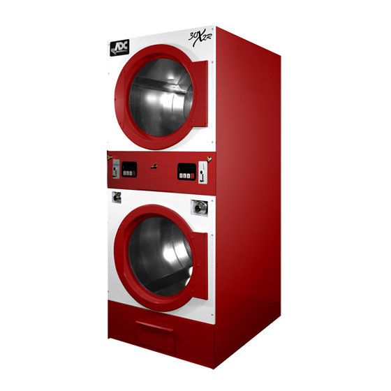
AD-30x2(R)(i)
Telephone: +1 (508) 678-9000 / Fax: +1 (508) 678-9447
AVERTISSEMENT: Assurez-vous de
bien suivre les instructions données dans
cette notice pour réduire au minimum le
risque d'incendie ou d'explosion ou pour
éviter tout dommage matériel, toute
blessure ou la mort.
—Ne pas entreposer ni utiliser d'essence
ni d'autres vapeurs ou liquides
inflammables à proximité de cet
appareil ou de tout autre appareil.
—QUE FAIRE SI VOUS SENTEZ UNE
ODEUR DE GAZ:
Ne pas tenter d'allumer d'appareils.
G
Ne touchez à aucun interrupteur. Ne
G
pas vous servir des téléphones se
trouvant dans le bâtiment.
Évacuez la pièce, le bâtiment ou la
G
zone.
Appelez immédiatement votre
G
fournisseur de gaz depuis un voisin.
Suivez les instructions du fournisseur.
Si vous ne pouvez rejoindre le
G
fournisseur de gaz, appelez le service
des incendies.
—L'installation et l'entretien doivent être
assurés par un installateur ou un
service d'entretien qualifié ou par le
fournisseur de gaz.
American Dryer Corporation
88 Currant Road
Fall River MA 02720-4781 USA
e-mail: techsupport@amdry.com
www.adclaundry.com
ADC Part No. 113019- 7
Advertisement
Table of Contents

Related Manuals for ADC AD-30x2 Series


Summary of Contents for ADC AD-30x2 Series
- Page 1 American Dryer Corporation 88 Currant Road Fall River MA 02720-4781 USA Telephone: +1 (508) 678-9000 / Fax: +1 (508) 678-9447 e-mail: techsupport@amdry.com www.adclaundry.com ADC Part No. 113019- 7...
- Page 2 Replacement parts can be obtained from your reseller or the ADC factory. When ordering replacement parts from the factory, you can FAX your order to ADC at +1 (508) 678-9447 or telephone your order directly to the ADC Parts Department at +1 (508) 678-9000. Please specify the dryer model number and serial number in addition to the description and part number, so that your order is processed accurately and promptly.
-
Page 3: Table Of Contents
WARNING In the State of Massachusetts, the following installation instructions apply: Proposition 65 I Installations and repairs must be performed by a qualified or licensed contractor, plumber, or Use of this product could expose you to gasfitter qualified or licensed by the State of substances from fuel combustion that contain Massachusetts. -
Page 4: Safety Precautions
Safety Precautions ___________________ A program should be established for the inspection and cleaning of lint in the burner area, exhaust ductwork, and area WARNING around the back of the dryer. The frequency of inspection and cleaning can best be determined from experience at each location. - Page 5 WARNING NOTES _____________________________________________________ Disconnect power before resetting the hi-limit. The hi-limit is located on the rear opening of the lint compartment. Press and release and the hi-limit will ____________________________________________________________ reset. ____________________________________________________________ CE ONLY ____________________________________________________________ IMPORTANT: This appliance must only be installed and operated in the country of destination indicated on the dryer’s data plate.
-
Page 6: Specifications
Specifications _____________________________________________________________________ MAXIMUM CAPACITY (DRY WEIGHT) 30 lb 13.6 kg PER POCKET 76.2 cm TUMBLER DIAMETER 30” 68.5 cm TUMBLER DEPTH 27” TUMBLER VOLUME 11 cu ft 311.5 L PER POCKET TUMBLER / DRIVE MOTOR 1/4 hp 0.19 kW PER POCKET 0.37 kW BLOWER / FAN MOTOR 1/2 hp... -
Page 7: Installation Procedures
Installation Procedures ______________ Dryer must be exhausted to the outdoors in an area where correct exhaust venting can be achieved as noted in this Installation should be performed by competent technicians in manual (refer to Exhaust Requirements section). accordance with local and state codes. In the absence of Dryer must be located in an area where correct exhaust venting these codes, the installation must conform to applicable can be achieved as noted in this manual (refer to Exhaust... -
Page 8: Fresh Air Supply Requirements
Fresh Air Supply Requirements ______ Exhaust Requirements _______________ This appliance may only be installed in a room that meets the IMPORTANT: Dryer should be located where a minimum appropriate ventilation requirements specified in the national amount of exhaust duct will be necessary. installation regulations. - Page 9 IMPORTANT: The dryer exhaust duct must not be This calculation of 45 feet (13.7 meters) compensates or connected to any gas vent, chimney, wall, ceiling, or allows for the use of a maximum of two elbows. Refer to the concealing space of a building. illustration below.
-
Page 10: Electrical Information
Electrical Information ________________ Electrical Service Specifications Gas Models Only Electrical Requirements ELECTRICAL SERVICE SPECIFICATIONS (PER DRYER) All electrical connections must be made by a properly licensed and competent electrician. This is to ensure that the electrical IMPORTANT: 208 VAC AND 230/240 VAC ARE NOT THE SAME. When ordering, installation is adequate and conforms to local and state specify exact voltage. -
Page 11: Gas Information
Electrical Connections WARNING A wiring diagram is located inside the control box for connection data. Fire or explosion could result due to failure of isolating or disconnecting gas supply as noted. If local codes permit, power to the dryer can be made by the use of a flexible UL listed power cord/pigtail (wire size must conform to rating of dryer), or the dryer can be hard wired Gas Supply... -
Page 12: Preparation For Operation / Start-Up
L.P. Gas Dryers made for use with L.P. gas have the gas valve’s internal pressure regulator blocked open so that the gas pressure must be regulated upstream of the dryer. The pressure measured at each gas valve pressure tap must be a consistent 10.5 in WC (26.1 mb). -
Page 13: Preoperational Test
Preoperational Test __________________ Preoperational Instructions __________ Coin Models All dryers are thoroughly tested and inspected before leaving Microprocessor Controller (Computer) the factory. However, a preoperational test should be performed before the dryer is publicly used. It is possible that When the microprocessor controller (computer) is in the ready adjustments have changed in transit or due to marginal location state, the L.C.D. -
Page 14: Warranty Information
The accumulation of lint can restrict Returning Warranty Parts this airflow. If the guidelines in this section are met, an ADC dryer will provide many years of efficient, trouble free, and All dryer or parts warranty claims or inquiries should be most importantly, safe operation. -
Page 15: Adjustments
NOTE: To prevent damage, avoid cleaning and/or touching area at the rear of the dryer. When contacting ADC, please ignitor/flame-probe assembly. have the model number and serial number available. -
Page 16: Non-Coin Programming
Non-Coin Programming _______________ SAIL SWITCH OPEN FAULT – Sail switch remained open after the cycle started. Should have closed. To Enter Programming Mode BURNER HIGH LIMIT FAULT – Burner temp. disk has opened. Press Keys Together BURNER IGNITION CONTROL – No signal to gas valve from To Exit Programming Mode Press Multiple Times (DSI) module during trial for ignition time. -
Page 17: Coin Programming
Coin Programming ____________________ Accessing and Clearing Coin Vault Total Enter program mode by switching program switch (up) while Enter Programming Mode By Placing no cycle is in progress. The Programming Switch On The Phase 7 Board Up Press HI – “Coin Vault total is $XXX” will appear. While No Cycle Is In Progress. - Page 18 ADC Part No. 113019 7 - 08/20/14...
Need help?
Do you have a question about the AD-30x2 Series and is the answer not in the manual?
Questions and answers