Table of Contents
Advertisement
Advertisement
Table of Contents

Related Manuals for Hitachi 88-06-0x


Summary of Contents for Hitachi 88-06-0x
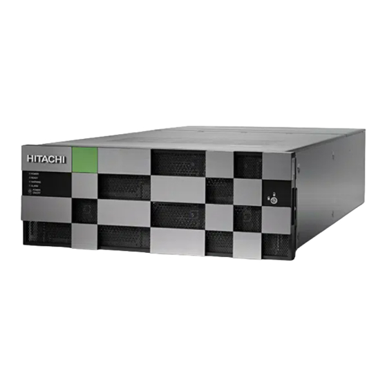
- Page 1 Hitachi Virtual Storage Platform G900 88-06-0x Hardware Reference Guide This document provides information about the system hardware components and the mechanical and environmental specifications for the Hitachi Virtual Storage Platform G900 storage system. MK-97HM85014-06 July 2020...
- Page 2 Materials. “Materials” mean text, data, photographs, graphics, audio, video and documents. Hitachi reserves the right to make changes to this Material at any time without notice and assumes no responsibility for its use. The Materials contain the most current information available at the time of publication.
-
Page 3: Table Of Contents
16-Gbps Fibre Channel (2-port) board LEDs and connectors....24 PCIe module................... 25 LAN blade LEDs and connectors..............26 Back-end modules..................27 Chapter 3: Drive trays................28 Small form-factor drive tray (DBS/DBSE)............28 Contents Hitachi Virtual Storage Platform G900 Hardware Reference Guide... - Page 4 Powering off the storage system................53 Battery unit......................54 Removing cables....................55 Appendix A: Storage system parts list..........56 VSP G900 parts list....................56 Drive tray and drive configuration..............63 Data and power cable model list................64 Contents Hitachi Virtual Storage Platform G900 Hardware Reference Guide...
- Page 5 AC connections..................106 Power cable usage guidelines..............108 Three-phase power considerations for racks..........108 Cable management..................108 Appendix E: Power distribution units for Hitachi Universal V2B Rack .....................109 Americas single-phase PDU 1P30A-8C13-3C19UL.P........109 Americas single-phase PDU 1P30A-15C13-3C19UL.P........110 Americas three-phase PDU 3P30A-8C13-3C19UL.P........111 Americas three-phase PDU 3P30A-15C13-3C19UL.P........
- Page 6 Dense intermix drive tray power supply............129 CMA (used to secure dense intermix drive tray)..........130 Battery......................130 Host port expansion chassis................130 PCIe switch board....................131 Appendix H: Environmental notices..........133 Appendix I: Regulatory compliance..........134 Contents Hitachi Virtual Storage Platform G900 Hardware Reference Guide...
-
Page 7: Preface
Preface This guide describes the hardware features and specifications of the Hitachi Virtual Storage Platform G900. Intended audience This document is intended for Hitachi Vantara representatives, system administrators, authorized service providers, or customers who install, configure, and operate the VSP Gx00 models. -
Page 8: Product Version
ARISING IN ANY WAY OUT OF THE USE OF THIS SOFTWARE, EVEN IF ADVISED OF THE POSSIBILITY OF SUCH DAMAGE. Product version This document revision applies to VSP G900 firmware 88-06-0x or later. Release notes Read the release notes before installing and using this product. They may contain requirements or restrictions that are not fully described in this document or updates or corrections to this document. - Page 9 { a | b } indicates that you must choose either a or b. This document uses the following icons to draw attention to information: Icon Label Description Note Calls attention to important or additional information. Preface Hitachi Virtual Storage Platform G900 Hardware Reference Guide...
-
Page 10: Conventions For Storage Capacity Values
Logical capacity unit Value 1 block 512 bytes 1 cylinder Mainframe: 870 KB Open-systems: OPEN-V: 960 KB ■ Others: 720 KB ■ 1 KB 1,024 (2 ) bytes Preface Hitachi Virtual Storage Platform G900 Hardware Reference Guide... -
Page 11: Accessing Product Documentation
Getting help Hitachi Vantara Support Connect is the destination for technical support of products and solutions sold by Hitachi Vantara. To contact technical support, log on to Hitachi Vantara Support Connect for contact information: https://support.hitachivantara.com/en_us/ contact-us.html. Hitachi Vantara Community is a global online community for Hitachi Vantara customers, partners, independent software vendors, employees, and prospects. -
Page 12: Chapter 1: Overview
Chapter 1: Overview The Hitachi Virtual Storage Platform G900 is a versatile modular, rack-mountable hybrid array storage system equipped with drive boxes, supporting SAS drives, flash drives, and TLC-NAND flash module drives, scaled for various storage capacity configurations. The storage systems provide high performance operations by using multiple controllers with high-speed processors, dual in-line cache memory modules (DIMMs), cache flash memory (CFM), battery, fans and ports to connect iSCSI and Fibre Channel I/O modules. - Page 13 Supports flash drive tray (DBF) requiring 2U of rack space and up to 12 flash module ■ drives (FMD) can be installed Supports system environments with mixed operating systems such as UNIX, Linux, ■ Windows, and VMware Chapter 1: Overview Hitachi Virtual Storage Platform G900 Hardware Reference Guide...
-
Page 14: Chapter 2: System Controller
Each controller includes the following internal components such as a processor, dual in- line cache memory modules (DIMMs), cache flash memory (CFM), battery, and fans. The controller has an Ethernet connection for out-of-band management using Hitachi Device Manager - Storage Navigator. If the data path through one controller fails, all drives remain available to data hosts using a redundant data path through the other controller. - Page 15 ALARM LED Off: Normal operation. Red: Processor failure (system might be down). For assistance, contact customer support: https:// support.hitachivantara.com /en_us/contact-us.html. POWER ON/OFF (main Powers the storage system. switch) Chapter 2: System controller Hitachi Virtual Storage Platform G900 Hardware Reference Guide...
-
Page 16: Cbl Controller Front Panel Leds (Without Bezel)
(SIM) are issued: 452xxx, 462xxx, 3077xx, 4100xx, and 410100. Controllers Controller 1 (bottom) and Controller 2 (top). Backup module Chapter 2: System controller Hitachi Virtual Storage Platform G900 Hardware Reference Guide... - Page 17 Blink red one time: Main battery failure. Blink red two times: Backup battery failure. Blink red three times: Both batteries failed or preventive maintenance replacement of batteries can run. Chapter 2: System controller Hitachi Virtual Storage Platform G900 Hardware Reference Guide...
-
Page 18: Cbl Controller Rear Panel Leds
Back end module LAN blade CBL controller power supply unit LEDs and connectors The following table lists the definitions of the CBL controller power supply unit LEDs and connectors. Chapter 2: System controller Hitachi Virtual Storage Platform G900 Hardware Reference Guide... -
Page 19: Host, Network, And Drive Tray Ports And Leds
VSP G130, G/F350, G/F370, G/F700, G/F900 storage systems support Fibre Channel (FC) and iSCSI FEMs for attachment to host servers. The front-end module LEDs indicate the operating status of the module. Chapter 2: System controller Hitachi Virtual Storage Platform G900 Hardware Reference Guide... -
Page 20: 10-Gbps Iscsi Board Leds And Connectors (Optical)
Red: Small form-factor (SFF) pluggable can be removed. Blue: Normal link status. Blink blue: Front-end module is in communication status. iSCSI connectors Connect to Ethernet cables. 10-Gbps iSCSI board LEDs and connectors (copper) Chapter 2: System controller Hitachi Virtual Storage Platform G900 Hardware Reference Guide... - Page 21 Off: No link connection. PORT LED Green: Link connection is established. Blinking: Communication is in progress. Off: No link connection or not ready to communicate. iSCSI connectors Connect to Ethernet cables. Chapter 2: System controller Hitachi Virtual Storage Platform G900 Hardware Reference Guide...
-
Page 22: 8-Gbps, 16-Gbps, Or 32-Gbps Fibre Channel (4-Port) Board Leds And Connectors
Connect to Fibre Channel cables. STATUS LED Green: Front-end module is in power-on state. Red: Front-end module can be removed safely. PORT LED Red: Small form-factor (SFF) pluggable can be removed. Chapter 2: System controller Hitachi Virtual Storage Platform G900 Hardware Reference Guide... - Page 23 8-Gbps, 16-Gbps, or 32-Gbps Fibre Channel ports (left to right) CHB number Port 1 Port 2 Port 3 Port 4 CHB-1A CHB-1B CHB-1C CHB-1D CHB-1E CHB-1F CHB-1G CHB-1H CHB-2A CHB-2B CHB-2C CHB-2D CHB-2E CHB-2F CHB-2G CHB-2H Chapter 2: System controller Hitachi Virtual Storage Platform G900 Hardware Reference Guide...
-
Page 24: 16-Gbps Fibre Channel (2-Port) Board Leds And Connectors
4-Gbps or 8-Gbps. Fibre Channel connectors Connect to Fibre Channel cables. Port assignments 16-Gbps Fibre Channel ports (left to right) CHB number Port 1 Port 2 CHB-1A CHB-1B Chapter 2: System controller Hitachi Virtual Storage Platform G900 Hardware Reference Guide... -
Page 25: Pcie Module
16-Gbps Fibre Channel ports (left to right) CHB number Port 1 Port 2 CHB-1C CHB-1D CHB-1E CHB-1F CHB-1G CHB-1H CHB-2A CHB-2B CHB-2C CHB-2D CHB-2E CHB-2F CHB-2G CHB-2H PCIe module Chapter 2: System controller Hitachi Virtual Storage Platform G900 Hardware Reference Guide... -
Page 26: Lan Blade Leds And Connectors
LAN port used by the user. LAN 1 Maintenance LAN port used by service personnel. LAN ALARM LED Red: LAN blade can be removed. Uninterruptible power supply (UPS) port Chapter 2: System controller Hitachi Virtual Storage Platform G900 Hardware Reference Guide... -
Page 27: Back-End Modules
Red: Back-end module can be removed safely. PORT LED Blue: Link status is normal. PATH 0 connector Connect to a drive tray. PATH 1 connector Connects to a drive tray. Chapter 2: System controller Hitachi Virtual Storage Platform G900 Hardware Reference Guide... -
Page 28: Chapter 3: Drive Trays
2U (88.2 mm) 2.5 inch (SFF) SFF with front panel bezel Number Item Description POWER LED Green: Drive tray is powered on. READY LED Green: Drive tray is operational. Chapter 3: Drive trays Hitachi Virtual Storage Platform G900 Hardware Reference Guide... -
Page 29: Sff Front Panel Without Bezel
Can be turned on or ■ turned off by the maintenance utility. ALM LED Red: Drive stopped due to a failure and can be replaced. ACT LED Green: Normal operation. Chapter 3: Drive trays Hitachi Virtual Storage Platform G900 Hardware Reference Guide... -
Page 30: Sff Rear Panel
ALARM LED Red: ENC can be replaced. PATH (IN) LED Blue: IN side port is linked PATH (IN) connector Connects to a controller or drive tray. Chapter 3: Drive trays Hitachi Virtual Storage Platform G900 Hardware Reference Guide... -
Page 31: Ac Power Supply Unit Leds And Connectors
The DBSE and DBLE power supply has a Platinum efficiency rating. Number Item Description RDY LED Green: Normal operation. ACI IN LED Green: AC input is operating normally. Chapter 3: Drive trays Hitachi Virtual Storage Platform G900 Hardware Reference Guide... -
Page 32: Large Form-Factor Drive Tray (Dbl/Dble)
READY LED Green: Drive tray is operational. Locate LED Amber: Indicates the location of ■ the chassis. Can be turned on or ■ turned off by the maintenance utility. Chapter 3: Drive trays Hitachi Virtual Storage Platform G900 Hardware Reference Guide... -
Page 33: Lff Front Panel Without Bezel
ACT LED Green: Normal operation. Blink green: Drive is being accessed. ALM LED Red: Drive stopped due to a failure and can be replaced. Chapter 3: Drive trays Hitachi Virtual Storage Platform G900 Hardware Reference Guide... -
Page 34: Lff Rear Panel
PATH (IN) connector Connects to a controller or drive tray. PATH (OUT) LED Blue: OUT side port is linked up. PATH (OUT) connector Connects to a drive tray. Chapter 3: Drive trays Hitachi Virtual Storage Platform G900 Hardware Reference Guide... -
Page 35: Ac Power Supply Unit Leds And Connectors
The DBSE and DBLE power supply has a Platinum efficiency rating. Number Item Description RDY LED Green: Normal operation. ACI IN LED Green: AC input is operating normally. ALM LED Red: Power supply unit can be replaced. Chapter 3: Drive trays Hitachi Virtual Storage Platform G900 Hardware Reference Guide... -
Page 36: Flash Module Drive Tray (Dbf)
■ the chassis. Can be turned on or ■ turned off by the maintenance utility. Lock Locks and unlocks the front panel bezel by using the supplied key. Chapter 3: Drive trays Hitachi Virtual Storage Platform G900 Hardware Reference Guide... -
Page 37: Fmd Front Panel Without Bezel
Note: ACT indicator is only printed on some types of FMDs. POWER, READY, and Green: Drive tray is LOCATE LEDs powered on. Green: Drive tray is operational. Chapter 3: Drive trays Hitachi Virtual Storage Platform G900 Hardware Reference Guide... -
Page 38: Fmd Rear Panel
Green: ENC is in the power- on state. Locate LED Amber: Indicates the location of ■ the chassis. Can be turned on or ■ turned off by the maintenance utility. Chapter 3: Drive trays Hitachi Virtual Storage Platform G900 Hardware Reference Guide... -
Page 39: High-Density Intermix Drive Tray (Db60)
The following describes the physical specifications of the high-density drive tray. Number of Name Model name Height drive slots Drive type DB60 DW-F800- 4U (176 mm) 3.5 inch (LFF) DB60C Chapter 3: Drive trays Hitachi Virtual Storage Platform G900 Hardware Reference Guide... -
Page 40: Dense Intermix Drive Tray With Front Panel Bezel
■ the chassis. Can be turned on or ■ turned off by the maintenance utility. Lock Locks and unlocks the front panel bezel by using the supplied key. Chapter 3: Drive trays Hitachi Virtual Storage Platform G900 Hardware Reference Guide... -
Page 41: Dense Intermix Drive Tray Display Leds
On the left side of the preceding figure, the rear of the drive tray is at the top. Rear of drive tray: 48-59 ■ 36-47 ■ 24-35 ■ 12-23 ■ Front of drive tray: 00-11 ■ Chapter 3: Drive trays Hitachi Virtual Storage Platform G900 Hardware Reference Guide... -
Page 42: Dense Intermix Drive Tray Rear Panel
Blue: IN side port is linked PATH (IN) connector Connects to a controller or drive tray. Console This port is reserved. ALARM LED Red: ENC can be replaced. Chapter 3: Drive trays Hitachi Virtual Storage Platform G900 Hardware Reference Guide... - Page 43 Indicates the location of ■ the chassis. Can be turned on or ■ turned off by the maintenance utility. POWER LED Green: ENC is in the power- on state. Chapter 3: Drive trays Hitachi Virtual Storage Platform G900 Hardware Reference Guide...
-
Page 44: Chapter 4: Host Port Expansion Chassis
Green: Host port expansion is turned on. Amber: PCIe module is turned on. Off: PCIe module is turned off. Safety lock Lock or unlock the front bezel. PCIe switchboard Chapter 4: Host port expansion chassis Hitachi Virtual Storage Platform G900 Hardware Reference Guide... -
Page 45: Host Port Expansion Chassis Fan
Red: PCIe switchboard can be replaced safely. Off: PCIe switchboard is powered off. Host port expansion chassis fan Number Item Description ALM LED Red: Fan failure has occurred. Off: Normal operation. Chapter 4: Host port expansion chassis Hitachi Virtual Storage Platform G900 Hardware Reference Guide... -
Page 46: Pcie Cable Connector
Amber: Basic PCIe status changed from link up to link down and cables. Cables can be removed safely. Off: Basic PCIe is normal or not set. Chapter 4: Host port expansion chassis Hitachi Virtual Storage Platform G900 Hardware Reference Guide... -
Page 47: Host Port Expansion Chassis Power Supply
Host port expansion chassis power supply Number Item Description ALM / RDY LED Red: Host port expansion chassis power supply can be replaced safely. Green: Normal operation. Chapter 4: Host port expansion chassis Hitachi Virtual Storage Platform G900 Hardware Reference Guide... - Page 48 Host port expansion chassis power supply Number Item Description AC IN LED Blue: AC input is normal. Chapter 4: Host port expansion chassis Hitachi Virtual Storage Platform G900 Hardware Reference Guide...
-
Page 49: Chapter 5: Service Processor
The SVP is also available as a 64-bit software application provided by Hitachi Vantara. For the latest interoperability updates and details, see the SVP (Service Processor) OS and Hypervisor support report at https://support.hitachivantara.com/en_us/... -
Page 50: Service Processor Description
<model number><system serial number>/emergency.do. For example: Storage system model Storage system serial number number 8320004 456789 http://192.168.0.15/dev/ storage/8320004456789/ emergency.do 8340004 456789 http://192.168.0.15/dev/ storage/8340004456789/ emergency.do 8360004 456789 http://192.168.0.15/dev/ storage/8360004456789/ emergency.do Chapter 5: Service processor Hitachi Virtual Storage Platform G900 Hardware Reference Guide... -
Page 51: Svp (Windows 10 Enterprise) Front Panel
Turning on automatic Windows updates or using the manual Windows update ■ method. Installing antivirus software that has been tested and approved by Hitachi. ■ SVP (Windows 10 Enterprise) front panel The front panel of the physical SVP with Windows 10 Enterprise operating system is equipped with LEDs, a reset button, and a power button. - Page 52 After the Initial Startup Wizard is complete, the SVP can be used in non-bridge mode. In this mode, the cables can be removed from SVP ports LAN3 and LAN4 and attached to switches. For more information, contact customer support. Chapter 5: Service processor Hitachi Virtual Storage Platform G900 Hardware Reference Guide...
-
Page 53: Chapter 6: Maintaining The Storage System
The POWER LED changes from green to amber when the process is completed. 3. Verify the POWER LED on the front of the storage system changes from green to amber. Chapter 6: Maintaining the storage system Hitachi Virtual Storage Platform G900 Hardware Reference Guide... -
Page 54: Battery Unit
Up to 24 degrees Celsius 5 years Up to 30 degrees Celsius 5 years Up to 34 degrees Celsius 4 years Up to 40 degrees Celsius 3 years Chapter 6: Maintaining the storage system Hitachi Virtual Storage Platform G900 Hardware Reference Guide... -
Page 55: Removing Cables
SAS cable (2). To remove a LAN cable, push the top of the LAN cable connector (1) to release the latch and remove the LAN cable (2). Chapter 6: Maintaining the storage system Hitachi Virtual Storage Platform G900 Hardware Reference Guide... -
Page 56: Appendix A: Storage System Parts List
Appendix A: Storage system parts list The following parts list describes the standard and optional hardware components for the storage systems. For more information about the storage system, contact an Hitachi Vantara sales representative. VSP G900 parts list The VSP G900 includes the following standard and optional components. - Page 57 SFP for 32 Gbps Longwave 0-80 DW-F800-BAT Battery Note: 1. A DIMM of a particular capacity cannot be mixed with different capacities in a storage system configuration. Appendix A: Storage system parts list Hitachi Virtual Storage Platform G900 Hardware Reference Guide...
- Page 58 7.6 TB, TLC, 12 Gbps, SFF, 0-24 flash drive DKC-F810I-15RMGM 15 TB, TLC, 12 Gbps, SFF, 0-24 flash drive DKC-F810I-30RMGM 30 TB, TLC, 12 Gbps, SFF, 0-24 flash drive Appendix A: Storage system parts list Hitachi Virtual Storage Platform G900 Hardware Reference Guide...
- Page 59 7.6 TB, TLC, 12 Gbps, SFF, 0-24 flash drive DKC-F810I-15RMGM 15 TB, TLC, 12 Gbps, SFF, 0-24 flash drive DKC-F810I-30RMGM 30 TB, TLC, 12 Gbps, SFF, 0-24 flash drive Appendix A: Storage system parts list Hitachi Virtual Storage Platform G900 Hardware Reference Guide...
- Page 60 Table 14 DBLE optional drive tray components Model number Part description Quantity DKC-F810I-6R0H9M 6 TB, 3.5-inch, 7.2kmin, 12 0-12 Gbps SAS drive DKC-F810I-10RH9M 10 TB, 3.5-inch, 7.2kmin, 12 0-12 Gbps SAS drive Appendix A: Storage system parts list Hitachi Virtual Storage Platform G900 Hardware Reference Guide...
- Page 61 3.5 TB, MLC 12 Gbps, flash 0-12 module drive DKC-F810I-7R0FP 7 TB, MLC/TLC 12 Gbps, 0-12 flash module drive DKC-F810I-14RFP 14 TB, MLC/TLC 12 Gbps, 0-12 flash module drive Appendix A: Storage system parts list Hitachi Virtual Storage Platform G900 Hardware Reference Guide...
- Page 62 6 TB, 3.5-inch, 7.2kmin, 12 0-60 Gbps, SAS, drive DKC-F810I-10RHLM 10 TB, 3.5-inch, 7.2kmin, 12 0-60 Gbps, SAS, drive DKC-F810I-14RHLM 14 TB, 3.5-inch, 7.2kmin, 12 0-60 Gbps, SAS, drive Appendix A: Storage system parts list Hitachi Virtual Storage Platform G900 Hardware Reference Guide...
-
Page 63: Drive Tray And Drive Configuration
Maximum number of mountable drives Flash Controller Solid-state module chassis Drive trays Maximum SAS drive drive drive (FMD) DBS/DBSE 1,152 1,152 DBL/DBLE DB60 1440 1,200 Appendix A: Storage system parts list Hitachi Virtual Storage Platform G900 Hardware Reference Guide... -
Page 64: Data And Power Cable Model List
5 m SAS cable, including omega clips (2) DW-F800-SCQ10A 10 m SAS optical cable DW-F800-SCQ30A 30 m SAS optical cable DW-F800-SCQ1HA 100 m SAS optical cable Appendix A: Storage system parts list Hitachi Virtual Storage Platform G900 Hardware Reference Guide... - Page 65 30 m LC-LC optical cable for optical A-6515-JM50L 50 m LC-LC optical cable for optical A-6515-JM100L 100 m LC-LC optical cable for optical A-6515-JM200L 200 m LC-LC optical cable for optical Appendix A: Storage system parts list Hitachi Virtual Storage Platform G900 Hardware Reference Guide...
- Page 66 Data and power cable model list Model number Specification A-6515-JM300L 300 m LC-LC optical cable for optical Appendix A: Storage system parts list Hitachi Virtual Storage Platform G900 Hardware Reference Guide...
-
Page 67: Appendix B: System Specifications
2. Can be mounted on the RKU rack. For the mounting, special rails for the rack and decoration panels are required separately depending on the number of the mounted storage systems. 3. The value is at maximum level. Appendix B: System specifications Hitachi Virtual Storage Platform G900 Hardware Reference Guide... - Page 68 DBS/DBSE 126 VA consumption (VA) DBL/DBLE 144 VA 130 VA DB60 191 VA Air flow (m /min) DBS/DBSE 2.2 (m /min) DBL/DBLE 2.2 (m /min) 1.6 (m /min) Appendix B: System specifications Hitachi Virtual Storage Platform G900 Hardware Reference Guide...
- Page 69 2. Can be mounted on the RKU rack. For the mounting, special rails for the rack and decoration panels are required separately depending on the number of the mounted storage systems. 3. The value is at maximum level. Appendix B: System specifications Hitachi Virtual Storage Platform G900 Hardware Reference Guide...
- Page 70 1. When mounting storage system and mixing DBS/DBSE, DBL/DBLE, DBF, and DB60 drive trays, the maximum mountable quantity (unit) may vary. 2. Available as spare or data disks. Appendix B: System specifications Hitachi Virtual Storage Platform G900 Hardware Reference Guide...
- Page 71 Up to 75.2º F (24º C) 5 years Up to 86º F (30º C) 5 years Up to 93.2º (34º C) 4 years Up to 104º (40º C) 3 years Appendix B: System specifications Hitachi Virtual Storage Platform G900 Hardware Reference Guide...
- Page 72 Flash memory: 32 MB L3 cache memory: 4 MB SDRAM: 1 GB Data assurance method Data bus: Parity Cache memory: ECC (1 bit correction, 2 bit detection) Drive: Data assurance code Appendix B: System specifications Hitachi Virtual Storage Platform G900 Hardware Reference Guide...
-
Page 73: Electrical Specifications
Number of phases, cabling Single-phase with protective grounding Steady-state current 100V/ CBL: 4.0x2 SFF drive tray: 2.4x2/1.2x2 200V LFF drive tray: 1.9x2/1.0x2 FMD tray: 2.6x2/1.3x2 Dense intermix drive tray: -/3.0x2 Appendix B: System specifications Hitachi Virtual Storage Platform G900 Hardware Reference Guide... -
Page 74: Environmental Specifications
. The actual required power might exceed the value shown in the table when the tolerance is included. Environmental specifications The environmental specifications for the storage systems are described in the following table. Appendix B: System specifications Hitachi Virtual Storage Platform G900 Hardware Reference Guide... - Page 75 14°F to 95°F (-10°C to 35°C) (-10°C to 50°C) Transport, -22°F to 140°F -22°F to 122°F (-30°C to 50°C) storage (-30°C to 60°C) Temperature 10°C or less change rate (°C/h) Appendix B: System specifications Hitachi Virtual Storage Platform G900 Hardware Reference Guide...
- Page 76 Within 5 seconds (resonance point: 10 Hz or less) Transport 5.0 or less (packed) (m/s Impact State CBL controller and drive trays Operating 20 or less (m/s (10 ms, half sine wave) Non-operating 50 or less Appendix B: System specifications Hitachi Virtual Storage Platform G900 Hardware Reference Guide...
- Page 77 40ºC at an altitude of 950m (3000 feet) to 28ºC at an altitude of 3050m (1000 feet). The allowable ambient temperature is decreased by 1ºC for every 175m increase in altitude above 950m. Appendix B: System specifications Hitachi Virtual Storage Platform G900 Hardware Reference Guide...
- Page 78 Operating Gaseous contamination should be within ANSI/ISA S71.04-2013 G1 classification levels. Non-operating Recommends the data centers maintain a clean operating environment by monitoring and controlling gaseous contamination. Appendix B: System specifications Hitachi Virtual Storage Platform G900 Hardware Reference Guide...
- Page 79 Therefore, the rate of the noise occupied by high-frequency content is high. Appendix B: System specifications Hitachi Virtual Storage Platform G900 Hardware Reference Guide...
- Page 80 7.2 B to 8.1 B, according to the ambient temperature, drive configuration, and operating status. 4. When accessing the dense intermix drive tray, do not work for long times at the rear of the rack. Appendix B: System specifications Hitachi Virtual Storage Platform G900 Hardware Reference Guide...
- Page 81 The acoustic noise level of 90 dB or less in the operating environment table represents the current operating environment guidelines in which Hitachi storage systems are designed and manufactured for reliable operation when placed 2 meters from the source of the noise.
- Page 82 Environmental specifications State Condition Hitachi does not test storage systems and data drives (includes HDDs, SSDs, and FMDs) for compatibility with fire suppression systems and pneumatic sirens. Hitachi also does not provide recommendations or claim compatibility with any fire suppression systems and pneumatic sirens.
-
Page 83: Shared Memory
9.8m/s (1.0G) equivalent to NEBS (Network Equipment-Building System) Level3). Shared memory Using Hitachi software products, the number of pairs, migration plans, and pool capacities and virtual volumes depend on the amount of capacity of shared memory installed on the controller. - Page 84 Table 26 Minimum cache memory capacity required for shared memory function Shared Memory Function VSP G900 Base 256 GiB Extension1 256 GiB Extension2 256 GiB Extension3 256 GiB Appendix B: System specifications Hitachi Virtual Storage Platform G900 Hardware Reference Guide...
-
Page 85: Appendix C: Network Access
Establish connections from the controllers to the host computers. ■ Connect the storage system to the network, enabling storage system management ■ through Hitachi Command Suite or Hitachi Ops Center Administrator. Allow communication to the storage system from the SVP. ■ TCP/IP port assignments When you install your storage system, default ports must be opened to allow for incoming and outgoing requests. - Page 86 TCP/IP port assignments Port number Usage description Used by the SVP, Hitachi Storage Advisor, and Device Manager - Storage Navigatorto communicate through the HTTP protocol. UDP (SNMP uses this port to send traps from the storage system) . Used by SMI-S.
- Page 87 S is not used. or later Automatic 88-02-0x -xx/00 allocation or later CommonJettySt HTTP 8080 88-02-0x -xx/00 or later CommonJettySt HTTP 8210 RestAPIServerS HTTP 9210 DeviceJettyStart HTTP 8081 Appendix C: Network access Hitachi Virtual Storage Platform G900 Hardware Reference Guide...
-
Page 88: Controller Connections
■ Physical service processor connections The SVP is available as an optional, physical device provided by Hitachi Vantara or as a virtual guest host running on customer-provided ESX servers and VM/OS licenses and media. The SVP provides error detection and reporting and supports diagnostic and maintenance activities involving the storage system. - Page 89 SVP Guest OS (1 DKC) Windows 10 IoT Enterprise ■ 2 x vCPU ■ 1 virtual network adapter ■ 4 GB RAM ■ 120 GB disk space ■ Appendix C: Network access Hitachi Virtual Storage Platform G900 Hardware Reference Guide...
-
Page 90: Appendix D: Data And Power Cables
Serial-attached SCSI (SAS) cables are used to connect drive trays to controllers and other drive trays. Appendix D: Data and power cables Hitachi Virtual Storage Platform G900 Hardware Reference Guide... - Page 91 Fibre Channel cable length based on cable size and port speed. Cable size Speed Maximum cable length 9 micron 1 Gbps 1 km (3281 ft) 2 Gbps 2 km Appendix D: Data and power cables Hitachi Virtual Storage Platform G900 Hardware Reference Guide...
-
Page 92: Fibre Channel Cables
Note: Due to high-speed serial data transfer via Fibre Channel, use high- quality FC cables that comply with the Fibre Channel-PH standard. The following figure shows FC direct connection and FC connection through a switch. Appendix D: Data and power cables Hitachi Virtual Storage Platform G900 Hardware Reference Guide... - Page 93 114.8 ft (35 m) 328.08 ft (100 410.1 ft (125 m) — 32 Gbps 65.62 ft (20 m) 229.7 ft (70 m) 328.08 ft (100 — Appendix D: Data and power cables Hitachi Virtual Storage Platform G900 Hardware Reference Guide...
- Page 94 Wavelength: (OMx) 850 nm LC-LC cable DXLC-2PS- 9/125 μm (longwave) SPC-xxM- Singlemode Wavelength: 10/125-2SR 1300 nm The following figure shows the connector used for optical interfaces. Appendix D: Data and power cables Hitachi Virtual Storage Platform G900 Hardware Reference Guide...
-
Page 95: Iscsi Cables
Interface name Cable One side Other side LC-LC cable Optical Equivalent 50, 125 mm to DXLC-2P- Multimode connector connector PC-xxM- Wavelength: GC50, 850 nm 125-2SR (OMx) Appendix D: Data and power cables Hitachi Virtual Storage Platform G900 Hardware Reference Guide... - Page 96 LC connector type ■ Connector type: LC duplex receptacle connector ■ Interval: 6.25 mm flat type, two rows ■ Cable specifications for 10 Gbps iSCSI copper interface Appendix D: Data and power cables Hitachi Virtual Storage Platform G900 Hardware Reference Guide...
- Page 97 50 m 10 Gbps 10GBASE-T STP ( use an RJ-45 LAN cable STP cable that suppresses radio noise) The following figure shows a 10 Gbps iSCSI cable. Appendix D: Data and power cables Hitachi Virtual Storage Platform G900 Hardware Reference Guide...
-
Page 98: Iscsi Standards
255 (maximum per iSCSI With Linux software port) initiator, the maximum number decreases. Path failover HDLM Supports Microsoft MPIO (Multi Path I/O) Link 10 Gbps SFP+ Appendix D: Data and power cables Hitachi Virtual Storage Platform G900 Hardware Reference Guide... - Page 99 When an iSCSI Port IPv6 is set to Enabled, verify the IPv6 router is connected to the same network, and then set IPv6 global address automatically. Appendix D: Data and power cables Hitachi Virtual Storage Platform G900 Hardware Reference Guide...
- Page 100 Header digest Supported Detects header error or data error with iSCSI communication. The storage system follows the host's digest setting. If digest is enabled, the performance degrades. Appendix D: Data and power cables Hitachi Virtual Storage Platform G900 Hardware Reference Guide...
-
Page 101: Managing Cables
ASCII-coded, hexadecimal, EUI-64 identifier. Example: eui.0123456789abcdef Managing cables Organize cables to protect the integrity of your connections and allow proper airflow around your storage system. Appendix D: Data and power cables Hitachi Virtual Storage Platform G900 Hardware Reference Guide... - Page 102 Fibre Channel 40 mm (1.73 inch) iSCSI optical 40 mm (1.73 inch) Category 5 Ethernet Four times the outside diameter of the cable 40 mm (1.73 inch) Appendix D: Data and power cables Hitachi Virtual Storage Platform G900 Hardware Reference Guide...
- Page 103 Cabling full-width modules When cabling full-width modules, route the cables horizontally, so that they do not interfere when replacing a module. Ensuring adequate airflow Appendix D: Data and power cables Hitachi Virtual Storage Platform G900 Hardware Reference Guide...
-
Page 104: Ac Power Cables
■ AC power cables Utility AC power standards for connector types and voltage levels vary by country. Hitachi provides a variety of power cables that facilitate using storage systems around the world. Hitachi power cables meet the safety standards for the country for which they are intended. - Page 105 South Africa 200-240 10, 16 SABS-164 Switzerland 200-240 SEV 1011 International 200-240 IEC 309 United 200-240 BS-1363 Kingdom International 200-240 IEC 309 International 200-240 IEC 309 Appendix D: Data and power cables Hitachi Virtual Storage Platform G900 Hardware Reference Guide...
-
Page 106: Ac Connections
3 IEC 83 NEMA L6-20P 200V-240V 1 ANSI C73.11 2 NEMA 6-15P 3 IEC 83 CEE 7/7 200V-240V 4 CEE (7) II, IV, VII 3 IEC 83 Appendix D: Data and power cables Hitachi Virtual Storage Platform G900 Hardware Reference Guide... - Page 107 AC connections Reference Description Receptacle Input rating standards BS-1363 200V-240V 5 BS 1365 3 IEC 83 AS-3112 200V-240V 6 AS C112 Cable and connector Appendix D: Data and power cables Hitachi Virtual Storage Platform G900 Hardware Reference Guide...
-
Page 108: Power Cable Usage Guidelines
Power cable usage guidelines Power cable usage guidelines Hitachi storage systems are intended for rack installation and ship with power cords. Installation and service requirements may require additional cords and cables to be ordered. The type of power cable required by a given installation is determined primarily by the: Type of AC line feed provided by the facility. -
Page 109: Appendix E: Power Distribution Units For Hitachi Universal V2B Rack
Balance the electrical current load between available PDUs. ■ Americas single-phase PDU 1P30A-8C13-3C19UL.P The following figure and table describe the specifications of the PDU. Figure 1 Americas PDU for the Hitachi Universal V2B Rack (Single-phase PDU 1P30A-8C13-3C19UL.P) Power Total rack... -
Page 110: Americas Single-Phase Pdu 1P30A-15C13-3C19Ul.p
4.5 m (14.76 feet) cable Americas single-phase PDU 1P30A-15C13-3C19UL.P The following figure and table describe the specifications of the PDU. Figure 2 Americas PDU for the Hitachi Universal V2B Rack (Single-phase PDU 1P30A-15C13-3C19UL.P) Power Total rack Part Power input... -
Page 111: Americas Three-Phase Pdu 3P30A-8C13-3C19Ul.p
Americas three-phase PDU 3P30A-8C13-3C19UL.P Americas three-phase PDU 3P30A-8C13-3C19UL.P The following figure and table describe the specifications of the PDU. Figure 3 Americas PDU for the Hitachi Universal V2B Rack (Three-phase PDU 3P30A-8C13-3C19UL.P) Power Total rack Part Power input output per... -
Page 112: Americas Three-Phase Pdu 3P30A-24C13-6C19Ul.p
Americas three-phase PDU 3P30A-24C13-6C19UL.P Figure 4 Americas PDU for the Hitachi Universal V2B Rack (Three-phase PDU 3P30A-15C13-3C19UL.P) Power Total rack Part Power input output per amperage number Region Quantity per PDU available 3P30A-15C Americas 4/rack Three phase 15 IEC C13 77A (16kVA) 13-3C19UL. -
Page 113: Apac And Emea Single-Phase Pdu 1P32A-9C13-3C19Ce.p
APAC and EMEA single-phase PDU 1P32A-9C13-3C19CE.P Figure 5 Americas PDU for the Hitachi Universal V2B Rack (Three-phase PDU 3P30A-24C13-6C19UL.P) Power Total rack Part Power input output per amperage number Region Quantity per PDU available 3P30A-24C Americas 2/rack Three phase 24 IEC C13 38.4A (8kVA) -
Page 114: Apac And Emea Single-Phase Pdu 1P32A-18C13-3C19Ce.p
APAC and EMEA single-phase PDU 1P32A-18C13-3C19CE.P Figure 6 APAC and EMEA PDU for the Hitachi Universal V2B Rack (Single-phase 1P32A-9C13-3C19CE.P) Power Total rack Part Power input output per amperage number Region Quantity per PDU available 1P32A-9C1 APAC and 6/rack Single phase 9 IEC C13 + 77A (17.6kVA) -
Page 115: Apac And Emea Three-Phase Pdu 3P16A-9C13-3C19Ce.p
APAC and EMEA three-phase PDU 3P16A-9C13-3C19CE.P Figure 7 APAC and EMEA PDU for the Hitachi Universal V2B Rack (Single-phase 1P32A-18C13-3C19CE.P) Power Total rack Part Power input output per amperage number Region Quantity per PDU available 1P32A-18C APAC and 4/rack Single phase 18 IEC C13 77A (17.6kVA) -
Page 116: Apac And Emea Three-Phase Pdu 3P16A-15C13-3C19Ce.p
APAC and EMEA three-phase PDU 3P16A-15C13-3C19CE.P Figure 8 APAC and EMEA PDU for the Hitachi Universal V2B Rack (Three-phase 3P16A-9C13-3C19CE.P) Power Total rack Part Power input output per amperage number Region Quantity per PDU available 3P16A-9C1 APAC and 6/rack Three phase 9 IEC C13 + 115A (26.4kVA) -
Page 117: Apac And Emea Three-Phase Pdu 3P32A-24C13-6C19Ce.p
APAC and EMEA three-phase PDU 3P32A-24C13-6C19CE.P Figure 9 APAC and EMEA PDU for the Hitachi Universal V2B Rack (Three-phase 3P16A-15C13-3C19CE.P) Power Total rack Part Power input output per amperage number Region Quantity per PDU available 3P16A-15C APAC and 4/rack Three phase 15 IEC C13 77A (17.6kVA) -
Page 118: Americas, Apac, And Emea Three-Phase Pdu 3P30A-243-69Ce-Ul.p
Americas, APAC, and EMEA three-phase PDU 3P30A-243-69CE-UL.P Figure 10 APAC and EMEA PDU for the Hitachi Universal V2B Rack (Three-phase 3P32A-24C13-6C19CE.P) Power Total rack Part Power input output per amperage number Region Quantity per PDU available 3P32A-24C APAC and 2/rack... - Page 119 Americas, APAC, and EMEA three-phase PDU 3P30A-243-69CE-UL.P Figure 11 APAC and EMEA PDU for the Hitachi Universal V2B Rack (Three-phase 3P30A-243-69CE-UL.P) Power Total rack Part Power input output per amperage number Region Quantity per PDU available 3P30A-243- Americas, 2/rack Three phase 24 IEC C13 77A (17.6kVA)
-
Page 120: Appendix F: Non-Hitachi Racks
PDUs and cable loops. Hitachi Universal V2 Rack rail kits Use rail kits to mount the Hitachi Virtual Storage Platform family storage system in a Hitachi Universal V2 Rack. The following tables list the rail kit information for the specified storage systems. -
Page 121: Hitachi Universal V2 Rack Accessories
2. CGR: Corner guide rail kit A3BF-HK-GL-740-1. Hitachi Universal V2 Rack accessories The following table provides rack accessory information for VSP G series storage systems. Table 28 Accessories for the Hitachi Universal V2 Rack Storage system Front door Rear door... - Page 122 Third-party rack support for DB60 dense intermix drive trays Appendix F: Non-Hitachi racks Hitachi Virtual Storage Platform G900 Hardware Reference Guide...
-
Page 123: Appendix G: Warning Labels On The Storage System
Use caution when handling equipment with movable parts. Use caution when handling equipment with hot surfaces. Use caution when handling equipment prone to tipping over. Appendix G: Warning labels on the storage system Hitachi Virtual Storage Platform G900 Hardware Reference Guide... -
Page 124: Cbl Controller
CBL controller CBL controller Appendix G: Warning labels on the storage system Hitachi Virtual Storage Platform G900 Hardware Reference Guide... -
Page 125: Small Form Factor Drive Tray
Small form factor drive tray Small form factor drive tray Appendix G: Warning labels on the storage system Hitachi Virtual Storage Platform G900 Hardware Reference Guide... -
Page 126: Large Form Factor Drive Tray
Large form factor drive tray Large form factor drive tray Appendix G: Warning labels on the storage system Hitachi Virtual Storage Platform G900 Hardware Reference Guide... -
Page 127: Flash Module Drive Tray
Flash module drive tray Flash module drive tray Appendix G: Warning labels on the storage system Hitachi Virtual Storage Platform G900 Hardware Reference Guide... -
Page 128: Dense Intermix Drive Tray
Dense intermix drive tray Dense intermix drive tray Appendix G: Warning labels on the storage system Hitachi Virtual Storage Platform G900 Hardware Reference Guide... -
Page 129: Cbl Controller
CBL controller CBL controller Dense intermix drive tray power supply Appendix G: Warning labels on the storage system Hitachi Virtual Storage Platform G900 Hardware Reference Guide... -
Page 130: Cma (Used To Secure Dense Intermix Drive Tray)
CMA (used to secure dense intermix drive tray) CMA (used to secure dense intermix drive tray) Battery Host port expansion chassis Appendix G: Warning labels on the storage system Hitachi Virtual Storage Platform G900 Hardware Reference Guide... -
Page 131: Pcie Switch Board
PCIe switch board PCIe switch board Appendix G: Warning labels on the storage system Hitachi Virtual Storage Platform G900 Hardware Reference Guide... - Page 132 PCIe switch board Appendix G: Warning labels on the storage system Hitachi Virtual Storage Platform G900 Hardware Reference Guide...
-
Page 133: Appendix H: Environmental Notices
They will dispose of it for you. This nickel-metal hydride battery, which is designated as recycling product by a recycling promotion low, must be recycled. The mark posted on the Cache Backup Battery is a three-arrow mark that indicates a recyclable part. Appendix H: Environmental notices Hitachi Virtual Storage Platform G900 Hardware Reference Guide... -
Page 134: Appendix I: Regulatory Compliance
Appendix I: Regulatory compliance This equipment has been tested and certified for compliance with the following standards. Appendix I: Regulatory compliance Hitachi Virtual Storage Platform G900 Hardware Reference Guide... - Page 135 All CB countries 1+A2 IEC60950-1:2005+A S_Mark Argentina 1+A2 TP TC 004/2011 Russia CNS 14336-1 BSMI Taiwan EN60950-1:2006+A1 CE marking 1+A1+A12+A2 Radio interference VCCI V-3/2015.4 VCCI Japan voluntary control Appendix I: Regulatory compliance Hitachi Virtual Storage Platform G900 Hardware Reference Guide...
- Page 136 This is a class A product. In a domestic environment this product can cause radio interference in which case the user can be required to take adequate measures. Appendix I: Regulatory compliance Hitachi Virtual Storage Platform G900 Hardware Reference Guide...
- Page 137 Hitachi Vantara Corporate Headquarters Contact Information 2535 Augustine Drive USA: 1-800-446-0744 Santa Clara, CA 95054 USA Global: 1-858-547-4526 HitachiVantara.com | community.HitachiVantara.com HitachiVantara.com/contact...
Need help?
Do you have a question about the 88-06-0x and is the answer not in the manual?
Questions and answers