Table of Contents
Advertisement
Quick Links
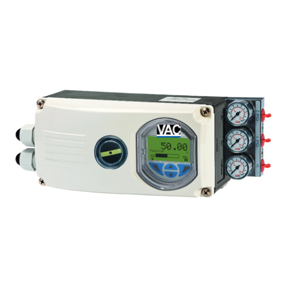
VAC D500 | OPERATING INSTRUCTION
Introduction
—
D500 Manual
The PositionMaster EDP300 has an integral mount
design, features a modular structure and offers an
outstanding price-performance ratio. Fully
automatic determination of the control parameters
and adaptation to the positioner allow for
considerable time savings as well as optimum
control behavior. Due to its characteristics, the
positioner is suited for even the most demanding
operating conditions.
Digital Positioner for the
positioning of pneumatically
controlled final control elements.
Additional Information
Additional documentation on PositionMaster
EDP300 is available for download free of charge at
www.abb.com/positioners.
Alternatively simply scan this code:
Advertisement
Table of Contents

Related Manuals for VAC D500


Summary of Contents for VAC D500
- Page 1 VAC D500 | OPERATING INSTRUCTION Digital Positioner for the positioning of pneumatically controlled final control elements. Introduction Additional Information — D500 Manual The PositionMaster EDP300 has an integral mount Additional documentation on PositionMaster design, features a modular structure and offers an EDP300 is available for download free of charge at outstanding price-performance ratio.
-
Page 2: Table Of Contents
Table of contents Change from one to two columns Safety ................4 Transport and storage ..........15 Inspection ................15 General information and instructions ........4 Transporting the device ............15 Warnings ..................4 Storing the device ..............15 Intended use ................5 Improper use ................ - Page 3 15 Additional documents ..........80 Commissioning ............37 Safety instructions ..............37 16 Accessories .............. 80 Checks prior to commissioning .......... 37 Extension modules ..............80 Mechanical mounting checks ..........37 Accessories ................80 Operation ..............39 Mounting material ............80 Pressure gauge block ............
-
Page 4: Safety
1 Safety Warnings General information and instructions These instructions are an important part of the product and The warnings in these instructions are structured as follows: must be retained for future reference. DANGER Installation, commissioning, and maintenance of the product may only be performed by trained specialist personnel who have The signal word ‘DANGER’... -
Page 5: Intended Use
Intended use Warranty provisions Positioning of pneumatically controlled actuators; designed for Using the device in a manner that does not fall within the scope mounting on linear and rotary actuators. of its intended use, disregarding this manual, using The device is designed for use exclusively within the stated underqualified personnel, or making unauthorized alterations values on the name plate and in the data sheet. -
Page 6: Use In Potentially Explosive Atmospheres
2 Use in potentially explosive atmospheres in accordance with ATEX and IECEx Mounting Note The installation, commissioning, maintenance and repair of Further information on the Ex-Approval of devices can be found devices in potentially explosive atmospheres must only be in the type examination certificates or the relevant certificates carried out by appropriately trained personnel. -
Page 7: Operation With Flammable Gases
ATEX and IECEx temperature data Operation with flammable gases Type of protection Ex i, intrinsic safety Observe the following points when operating a device with flammable gases: Temperature Ambient temperature Surface temperature • The device must be used in accordance with the class specifications in the relevant certificate. -
Page 8: Atex Und Iecex Electrical Data
… 2 Use in potentially explosive atmospheres in accordance with ATEX and IECEx ATEX und IECEx electrical data Type of protection Ex i, intrinsic safety Basic device Signal circuit (AI) Module for analog feedback (AO) Terminals +11 / 12 Terminals +31 / 32 Temperature class T1 –... -
Page 9: Type Of Protection Ex N - Non-Sparking
Type of protection Ex n - non-sparking Basic device Signal circuit (AI) Terminals +11 / 12 Electrical values 22 mA; U 30 V Digital input (DI) Terminals +81 / 82 Electrical values 30 V Digital output (DO) Terminals +83 / 84 Electrical values 30 V Option modules... -
Page 10: Use In Potentially Explosive Atmospheres
3 Use in potentially explosive atmospheres in accordance with FM and CSA Change from one to two columns Mounting Note The installation, commissioning, maintenance and repair of Further information on the Ex-Approval of devices can be found devices in areas with explosion hazard must only be carried out in the type examination certificates or the relevant certificates by appropriately trained personnel. -
Page 11: Operation With Flammable Gases
Temperature data Operation with flammable gases Note Observe the following points when operating a device with Legibility of the display is guaranteed at an ambient flammable gases: temperature of 20 to 70 °C. At 20 °C and lower, legibility can •... -
Page 12: Electrical Data
… 3 Use in potentially explosive atmospheres in accordance with FM and CSA Electrical data Basic device Signal circuit (AI) Module for analog feedback (AO) Terminals +11 / 12 Terminals +31 / 32 Temperature class T1 – T4 Temperature class T6 Temperature class T1 –... -
Page 13: Design And Function
4 Design and function Schematic diagram Basic device Optional upgrades M M 10112-01 A Electronics 7 Analog feedback B Pneumatics 8 Digital feedback C Position sensor 9 Emergency shutdown module 1 4 to 20 mA / Bus connection j Universal input 2 Digital input k Pressure sensor 3 Alarm output... -
Page 14: Principle Of Operation
… 4 Design and function Principle of operation The PositionMaster EDP300 is an electronically configurable positioner with communication capabilities designed for mounting on pneumatic linear or rotary actuators. Fully automatic determination of the control parameters and adaptation to the positioner allow for considerable time savings as well as optimum control behavior. -
Page 15: Transport And Storage
6 Transport and storage 7 Installation Inspection Safety instructions Check the devices immediately after unpacking for possible CAUTION damage that may have occurred from improper transport. Risk of injury due to incorrect parameter values! Details of any damage that has occurred in transit must be Incorrect parameter values can cause the valve to move recorded on the transport documents. -
Page 16: External Position Sensors
… 7 Installation External position sensors Note To connect the EDP300 Remote Sensor, a cable with the following specifications needs to be used: • 3-wire, cross-section 0.5 to 1.0 mm² • shielded, with at least 85 % coverage • Temperature range up to at least 100 °C (212 °F) The cable glands must also be approved for a temperature range up to at least 100 °C (212 °F). -
Page 17: Mechanical Mounting
Mechanical mounting General Operating range for linear actuators: The operating range for linear actuators is ±45° symmetrically to the longitudinal axis. The usable span within the operating range is at least 25° (recommended figure 40°). The usable span does not necessarily need to run symmetrically to the longitudinal axis. -
Page 18: Mounting On Linear Actuators
… 7 Installation … Mechanical mounting Mounting on linear actuators For mounting on a linear actuator in accordance with DIN / IEC 534 (lateral mounting as per NAMUR), the following attachment kit is available: M10411-01 Figure 7: Attaching a follower guide to the actuator 1. - Page 19 4. Hold the prepared positioner (with the mount bracket still loose) on the actuator so that the follower pin for the lever enters the follower guide to determine which tap holes on the positioner must be used for the mount bracket. 5.
- Page 20 … 7 Installation … Mechanical mounting Position of actuator bolt The actuator bolt for moving the potentiometer lever can be mounted permanently on the lever itself or on the valve stem. Depending on the mounting method, when the valve moves the actuator bolt performs either a circular or a linear movement with reference to the center of rotation of the potentiometer lever.
-
Page 21: Mounting On Control Valves
Mounting on control valves Mounting on rotary actuator For mounting on part-turn actuators in accordance with VDI / VDE 3845, the following attachment kit is available: M10128-01 1 Washers 3 O-ring 2 Screws 4 Lever Figure 14: Integral mounting on control valves M10130-01 Figure 16: Components of attachment kit •... - Page 22 … 7 Installation … Mechanical mounting M10421-01 1 Attachment bracket M10424-01 Figure 18: Screwing the attachment bracket onto the positioner Figure 17: Mounting the adapter on the positioner 1. Determine the mounting position (parallel to actuator or at 90° angle) 2.
-
Page 23: Electrical Connections
Electrical connections Safety instructions DANGER Risk of explosion for devices with local communication interface (LCI) A local communication interface (LCI) may not be operated in hazardous areas. • Never use the local communication interface (LCI) on the main board in a hazardous area! WARNING Risk of injury due to live parts! When the housing is open, contact protection is not provided... -
Page 24: Positioner / Edp300 Control Unit Electrical Connection
… 7 Installation … Electrical connections Positioner / EDP300 Control Unit Electrical Connection D Limit 1 Limit 2 51 52 53 41 42 43 Limit 1 Limit 2 +11 -12 +81 -82 +83 -84 +51 -52 +41 -42 +31 -32 +85 -86 +51 -52 +41 -42... -
Page 25: Edp300 Remote Sensor Electrical Connection
EDP300 Remote Sensor Electrical Connection Limit 1 Limit 2 Limit 1Limit 2 +51 -52 +41 -42 51 52 53 41 42 43 M10949 M10949 A Basic device 1 Position sensor B Options 2 Limit monitor with proximity switches (optional) 3 Limit monitor with microswitches (optional) Figure 21: EDP300 Remote Sensor Electrical Connection Change from one to two columns Electrical data for inputs and outputs... -
Page 26: Module For Analog Feedback Ao
… 7 Installation … Electrical connections Option modules Set point signal analog (two-wire technology) Module for analog feedback AO* Terminals +11 / 12 Without any signal from the positioner (e.g. ‘no power’ or ‘initializing’) the module sets the output to > 20 mA (alarm level). Nominal operating range 4 to 20 mA Limit values... -
Page 27: Module For The Emergency Shutdown Function
Module for the emergency shutdown function* Limit switch When the 24 V DC signal is interrupted, the I/P module executes The limit switch can either be equipped with proximity switches the respective safety function, depending on the mechanical or with potential-free microswitches. construction. -
Page 28: Connection On The Device
… 7 Installation … Electrical connections Connection on the device M 20 mm / 1/2" M10950 1 Blind plug 4 Terminals attachment set for digital feedback 2 Cable gland 5 Terminals basic device 3 Terminals for options modules Figure 22: Connection on device (example) Change from one to two columns Wire cross-sectional areas 2 tap holes ½- 14 NPT or M20 ×... - Page 29 Option modules Cross section Rigid / flexible wires 0.14 to 1.5 mm (AWG26 to AWG17) Flexible with wire end sleeve no 0.25 to 1.5 mm (AWG23 to AWG17) plastic sleeve Flexible with wire end sleeve 0.25 to 1.5 mm (AWG23 to AWG17) with plastic sleeve Multi-wire connection capacity (two wire with the same cross-section) Rigid / flexible wires...
-
Page 30: Connection To Device - Edp300 Control Unit With Edp300 Remote Sensor
… 7 Installation … Electrical connections Connection to device - EDP300 Control Unit with EDP300 Remote Sensor Housing 1 (EDP300 Control Unit) Housing 2 (EDP300 Remote Sensor) M 20 mm / M 20 mm / NPT 1/2" NPT 1/2" M10832-01 1 Terminals EDP300 Remote Sensor 3 EMC Cable gland 2 Terminal attachment kit for digital feedback... - Page 31 Electrical connection Connect the positioner (EDP300 Control Unit, housing 1) and remote position sensor (EDP300 Remote Sensor, housing 2), while following the instructions below: • The EDP300 Remote Sensor and the EDP300 Control Unit are adjusted to each other. Ensure that only devices with the same serial number are connected.
-
Page 32: Remote Position Sensor
… 7 Installation … Electrical connections Connection to device - EDP300 Control Unit for remote position sensor M 20 mm / M 20 mm / 1/2" 1/2" M10834-01 1 Terminals for remote position sensor 3 EMC Cable gland 2 Remote position sensor 4 Shielded connection cable Figure 24: Connection of EDP300 Control Unit with remote position sensor (example) Change from one to two columns... -
Page 33: Installing The Option Modules
Installing the option modules Electrical connection Note Connect the positioner (EDP300 Control Unit) and remote The supply voltage must be switched off before the option position sensor while observing the following instructions: modules are installed. • A shielded 3-wire cable with a maximum length of 10 m (33 ft) must be used for the connection. -
Page 34: Installing The Mechanical Position Feedback
… 7 Installation … Installing the option modules Installing the mechanical position feedback 1. Loosen the screws for the housing cover and remove it. 1. Loosen the screws for the housing cover and remove it. 2. Loosen all cable connections on the screw terminals. 2. -
Page 35: Setting The Mechanical Limit Switch With Proximity Switches
Setting the mechanical limit switch with proximity Setting the mechanical limit switch with 24 V switches microswitches 1. Loosen the screws for the housing cover and remove it. 2. Select the ‘Manual Adjustment’ operating mode and move the final control element by hand into the desired switching position for contact 1. -
Page 36: Pneumatic Connections
… 7 Installation Pneumatic connections Connection on the device Note The positioner must only be supplied with instrument air that is free of oil, water, and dust (in gas configuration with dried natural gas). The purity and oil content must meet the requirements of Class 3 according to DIN/ISO 8573-1. -
Page 37: Air Supply
8 Commissioning Safety instructions Air supply Note The electrical power supply and supply air pressure data indicated on the name plate must be complied with during Instrument air commissioning. Purity Maximum particle size: 5 m Maximum particle density: 5 mg/m Before switching on the device, make sure that your installation Oil content Maximum concentration 1 mg/m... - Page 38 … 8 Commissioning … Mechanical mounting checks Moving to end positions after completion of automatic Moving to end positions with a new device adjustment Process display Process display 1. Use to move to the relevant end positions. 1. Use to switch to the Operating Mode menu. -45.0 Operating mode Auto Adjust...
-
Page 39: Operation
9 Operation Safety instructions Menu navigation CAUTION Risk of injury due to incorrect parameter values! Incorrect parameter values can cause the valve to move unexpectedly. This can lead to process failures and result in injuries. • Before recommissioning a positioner that was previously in use at another location, always reset the device to its factory settings. -
Page 40: Menu Levels
… 9 Operation Menu levels There are three menu levels below the process display. Process display Information level Operating mode Diagnosis Auto Adjust Operator Page 1 Adaptive Signals View Control Manual SP Manual Sensor Configuration Configuration Easy Setup Device Setup Display Control Input/Output... -
Page 41: Process Display
Process display Switching to the information level (Operator Menu) On the information level, the operator menu can be used to display diagnostic information and choose which operator 50.0 pages to display. Position °% Process display M10240-01 1 Indication of measuring point 4 Symbol indicating tagging ‘Parameterization protected’... -
Page 42: Switching The Operating Mode
… 9 Operation Switching the operating mode The operating mode is displayed and changed in the operating Description of operating modes modes menu. Additionally, it is possible to switch to the configuration level Symbol Operating mode from there. Adaptive control active When the PositionMaster EDP300 positioner is operated Process display in ‘Adaptive Mode’, the control parameters are... -
Page 43: Start Automatic Adjustment
Start automatic adjustment Symbol Operating mode The Auto Adjust function of the device can be configured and Manual set point, fixed control started in the ‘Operating mode’ menu. The valve is adjusted manually within the stroke range using the direction buttons. Process display 1. -
Page 44: Switching To The Configuration Level (Parameterization)
… 9 Operation … Switching the operating mode Switching to the configuration level (parameterization) Note The ‘Autoadjust Mode’ can be preset at the configuration level in The device parameters can be displayed and changed on the ‘... / Easy Setup / Autoadjust Mode’. configuration level. -
Page 45: Error Messages On The Lcd Display
Error messages on the LCD display Numerical entry When a numerical entry is made, a value is set by entering the In the event of an error, a message consisting of a symbol and individual decimal positions. text appears at the bottom of the process screen (e. -
Page 46: Overview Of Parameters On The Configuration Level
… 9 Operation Overview of parameters on the configuration level Note This overview of parameters shows all the menus and parameters available on the device. Depending on the version and configuration of the device, not all of the menus and parameters may be visible in it. Easy Setup Language Actuator Type... - Page 47 Input/Output Digital Input DI Function DI Default SP DI Logic Alarm Output Alarm Logic DO Alarm Mask Alarm Simulation Alarm Maintenan. Alarm OoSpec. Alarm Check Fct. Alarm Failure Analog Feedback Analog Out Min. Analog Out Max. Feedbk. Charact. AO Alarm Mask Alarm Maintenan.
- Page 48 … 9 Operation … Overview of parameters on the configuration level SW 2 Mask Map Alarm Maintenan. Alarm OoSpec. Alarm Check Fct. Alarm Failure Universal input UI SP Value Max. UI SP Value Min. UI Damping UI Charact. UI Out Value Min UI Out Value Max Communication HART Version...
- Page 49 Device Info Hardware Rev. Software Rev. Mounting Date Commun. Tag Device Address Descriptor Device Message Pneumatic Type Stroke Time Up Stroke Time Dn Service Service Mode Factory Setting Adjust Sensors Adjust All Adjust Outputs Pneumatic Remote Sensor Sensor Type Sensor Calib. AO Alarm Current...
-
Page 50: Parameter Descriptions
… 9 Operation Parameter descriptions Menu Easy Setup Menu / parameter Value range Description Easy Setup Language English, Deutsch, Français, Selects the menu language Italiano, Español, Português Actuator Type Linear, Rotary Use this parameter to configure the positioner for operation on a linear actuator (sensor range ±30°) or on a rotary actuator (sensor range ±45°). - Page 51 Menu / parameter Value range Description Easy Setup (continued) Autoadjust Mode Full, Controller, Valve Range, Use this parameter to define the mode or scope of the Auto Adjust function. Zero, Locked • Full: Complete automatic adjustment • Controller: Determine control parameters only •...
-
Page 52: Menu Device Setup
… 9 Operation … Parameter descriptions Menu Device Setup Menu / parameter Value range Description Device Setup Actuator Type Linear, Rotary Use this parameter to configure the configuration-, parameterization instruction for the positioner for operation on a linear actuator (sensor range ±30°) or on a rotary actuator (sensor range ±45°). No mechanical modifications to the positioner are required. - Page 53 Setpoint Menu / parameter Value range Description Device Setup / Setpoint SP Range Min. 4.0 to 18.4 mA The setpoint range is the range of the input current as a percentage of the operating range of the fittings from 0 to 100 %. Use parameter ‘0’...
- Page 54 … 9 Operation … Parameter descriptions Menu / parameter Value range Description Device Setup / Setpoint (continued) SP Charact. Curve Linear Use this parameter to select a function that adjusts the behavior of the positioner to the analog input signal in accordance with a predefined course. This linearizes the characteristic curves for the valves and 1:25 AM fittings and improves the behavior of the overall control loop.
- Page 55 Menu: Range Settings Menu / parameter Value range Description Device Setup / Range Settings Valve Rng Calib. Upper Valve Rng 0.0 to 100.0 % Normally, the valve range is determined automatically during Auto Adjust. A partial run of Auto Adjust that is limited to the control parameters or valves and fittings without end stops, however, requires manual adjustment of the valve range.
- Page 56 … 9 Operation … Parameter descriptions Menu / parameter Value range Description Device Setup / Range Settings (continued) Upper Working Rng 0.0 to 100.0 % The working range can be configured to be smaller than the maximum mechanical working range. The set point range always refers to the configured working range.
- Page 57 End Stop Behav. Menu / parameter Value range Description Device Setup / End Stop Behav. Tight Shut 0% 0 to 45.0 The shut-off value is a percentage of the working range from which the 0 % position is approached. Once the specified position limit value is reached, the actuator moves into the 0% end position. Control at 0% On, Off Use this parameter to set the end position behavior.
-
Page 58: Menu: Display
… 9 Operation … Parameter descriptions Menu: Display Menu / parameter Value range Description Display Language English, Deutsch, Français, Selects the menu language Italiano, Español, Português Engineering Units Temperature Use this parameter to select the units to be displayed. Pressure •... -
Page 59: Menu: Controller
Menu: Controller Menu / parameter Value range Description Controller Zone 1 to 100 in steps of 1 This parameter specifies the point at which the control structure is switched over when the dead band is being approached. Note On valves where slip-stick effect is significant, valve vibration can be reduced by increasing the value of the ‘Zone’... - Page 60 … 9 Operation … Parameter descriptions Menu / parameter Value range Description Controller (continued) KP Up 1.0 to 400.0 Use this parameter to adjust the KP value for the up positioning direction (towards 100 %). The KP value is the gain of the controller. The control speed and stability are influenced by the KP value. With higher KP values, the control speed increases.
- Page 61 Menu / parameter Value range Description Controller (continued) Y-Offset Up 1 to 100.0 % Use this parameter to adjust the Y offset for the up positioning direction (towards 100 %). The ‘offset for the set point signal’ linearizes the behavior of the I/P module used and enables rapid compensation even in the case of small control deviations.
-
Page 62: Menu: Input/Output
… 9 Operation … Parameter descriptions Menu: Input/Output Menu / parameter Value range Description Input/Output Digital Input DI Function Selection of functions or states that are executed or adopted if the ‘digital input’ has been activated. DI Default SP DI Logic Alarm Output Alarm Logic Use this parameter to configure the alarm output via which a general alarm can be issued. - Page 63 Menu: Digital Input Menu / parameter Value range Description Input/Output / Digital Input DI Function • Off – No function Hold Last SP • Hold Last SP – Last set point is retained Hold User SP • Hold User SP – Substitute value for set point (defined in ‘DI Default Setup.’) Hold Last Pos.
- Page 64 … 9 Operation … Parameter descriptions Menu: Alarm Output Menu / parameter Value range Description Input/Output / Alarm Output Alarm Logic Active High, Active Low Use this parameter to define the contact logic for the alarm output. • Active High –> I > 2.1 mA •...
- Page 65 Menu: Digital Feedback Menu / parameter Value range Description Input/Output / Digital Feedback Switch 1 Switch 1 Funct. The function of switch 1 is configured in this parameter group. Switch 1 Value • Switch 1 Funct. – Switch 1 function Switch 1 Logic •...
- Page 66 … 9 Operation … Parameter descriptions Menu: SW 1 Mask Map Menu / parameter Value range Description Input/Output / Digital Feedback / SW 1 Mask Map Alarm Maintenan. On, Off When a general alarm is issued, an alarm current can be sent via the analog position feedback. These alarm groups are defined in accordance with Namur NE107.
- Page 67 Menu: Switch 2 Menu / parameter Value range Description Input/Output / Digit. Feedback / Switch 2 Switch 2 Funct. Position Info Use this parameter to select whether the switch is to be used as a limit signal generator or for signaling diagnostics messages.
-
Page 68: Menu: Communication
… 9 Operation … Parameter descriptions Menu: Communication Menu / parameter Value range Description Communication HART Version HART 5, HART 7 Use this parameter to define the HART protocol via which the device is to communicate. • HART 5 – HART® Protocol 5.9 •... -
Page 69: Menu: Diagnosis
Menu: Diagnosis Menu / parameter Value range Description Diagnosis Partial Stroke PS Configuration, PS ‘Partial Stroke Test’ is used to test the mobility of the safety-related valves and fittings. For this Interval, PS Start Now purpose, the valve is moved by a configurable amount in the direction of the safety position (venting of positioner output 1). - Page 70 … 9 Operation … Parameter descriptions Menu: Partial Stroke Menu / parameter Value range Description Diagnosis / Partial Stroke PS Configuration PS Vent Amount, • PS Vent Amount: Position change in the direction of the safety position (venting of positioner output 1) by which the valve is to be moved.
-
Page 71: Menu: Device Info
Menu: Device Info Note This menu is only used to display the device parameters. The parameters are displayed independently of the configured access level, but cannot be changed. Menu / parameter Value range Description Device Info Hardware Rev. The hardware revision is displayed here. Software Rev. -
Page 72: Menu: Service
… 9 Operation … Parameter descriptions Menu: Service Menu / parameter Value range Description Service Off, On * Service Mode Activate service mode. CAUTION Danger of crushing! If Service Mode is set to ‘On’, the valve moves to its pneumatic safety position. In the case of the ‘venting’... - Page 73 Menu / parameter Value range Description Service (continued) Remote Sensor* Off, On If an external position sensor is connected, this parameter must be set to ‘On’. Sensor Type * Standard Use this parameter to select the version of the installed position sensor. Non-Contact •...
-
Page 74: Diagnosis / Error Messages
10 Diagnosis / error messages Calling up the error description Additional details about the error that has occurred can be called up on the information level. Process display Electronics 1. Use to switch to the information level (Operator Menu). Operator Menu Diagnosis Back Select... -
Page 75: Possible Error Messages
Possible error messages Priority Fault message Possible cause Troubleshooting the Instrument Group Position measurement Defective position sensor Replace position sensor Sensor Failure * Valve blocked Friction too high Valve requires maintenance Actuator Positioning timeout - Check Positioning time up-scaled Valve requires maintenance Actuator valve maintenance friction high... - Page 76 … 10 Diagnosis / error messages … Possible error messages Priority Fault message Possible cause Troubleshooting the Instrument Group Leakage in actuator Leakage inside the actuator Check the actuator diaphragms Actuator Pressure NV Data defect Restart device Electronics Pressure NV chip defect Replace pressure option Electronics Overpressure from supply...
- Page 77 Priority Fault message Possible cause Troubleshooting the Instrument Group Binary input active Digital input activated by the Deactivate the digital input Special user Requirements Switchpoint 1 exceeded Valve has passed limit 1 position Depends on application Process Switchpoint 2 exceeded Valve has passed limit 2 position Depends on application Process Analog output supply fault...
-
Page 78: Maintenance
11 Maintenance 13 Recycling and disposal The positioner does not require any maintenance if it is used as Note intended under normal operating conditions. Products that are marked with the adjacent symbol may not be disposed of as unsorted municipal waste Note (domestic waste). -
Page 79: Supplemental Specifications
14 Supplemental specifications Transmission data and contributing Actuator travel factors Rotation angle Output Y1 Used range 25 … 270° for rotary actuator Increasing set point signal 0 to 100 % 25 … 60° for linear actuator Increasing pressure at output Actuator travel limit Min. -
Page 80: Ambient Conditions
… 14 Supplemental specifications 16 Accessories Ambient conditions Extension modules Mechanical position indicator Ambient temperature range Indicator disk in housing cover linked with device feedback During operation, storage, 40 to 85 °C ( 40 to 185 °F) shaft. and transport 40 to 100 °C ( 40 to 212 °F)* Contactless position sensor (optional) Increased temperature range only with EDP300 Remote Sensor. -
Page 81: Appendix
17 Appendix Return form Statement on the contamination of devices and components Repair and/or maintenance work will only be performed on devices and components if a statement form has been completed and submitted. Otherwise, the device/component returned may be rejected. This statement form may only be completed and signed by authorized specialist personnel employed by the operator. -
Page 82: Control Drawing 901305
… 17 Appendix Control Drawing 901305... - Page 84 … 17 Appendix … Control Drawing 901305...
- Page 86 … 17 Appendix … Control Drawing 901305...
- Page 88 Manufacturer ABB Automation Products GmbH Process Automation Schillerstr. 72 32425 Minden Germany Tel: +49 571 830-0 Fax: +49 571 830-1806 Customer service center Tel: +49 180 5 222 580 Mail: automation.service@de.abb.com...
- Page 89 VALVE ACCESSORIES & CONTROLS 200 Jade Park • Chelsea, AL 35043 TEL: 205.678.0507 info@vacaccessories.com...
Need help?
Do you have a question about the D500 and is the answer not in the manual?
Questions and answers