VAC V200 POSITIONER Installation,Operation And Maintenance Instruction
Feedback option
Hide thumbs
Also See for V200 POSITIONER:
- Fine tuning (2 pages) ,
- Mounting instructions (2 pages) ,
- Installation, calibration and troubleshooting manual (2 pages)
Table of Contents
Advertisement
Advertisement
Table of Contents

Related Manuals for VAC V200 POSITIONER


Summary of Contents for VAC V200 POSITIONER
- Page 1 V200 POSITIONER www.vacaccessories.com V200 FEEDBACK OPTION 92077r14...
-
Page 2: Table Of Contents
V200 POSITIONER www.vac.se CONTENTS 1 INTRODUCTION .................. 4 Principle of Operation .............. 4 1.2 Product Identification ............... 4 Safety Instructions ..............4 2 FEEDBACK INSTALLATION .............. 5 Connections ................5 Front cover and indicator ............5 2.2.1 Removing the front cover ............5 2.2.2... -
Page 3: Introduction
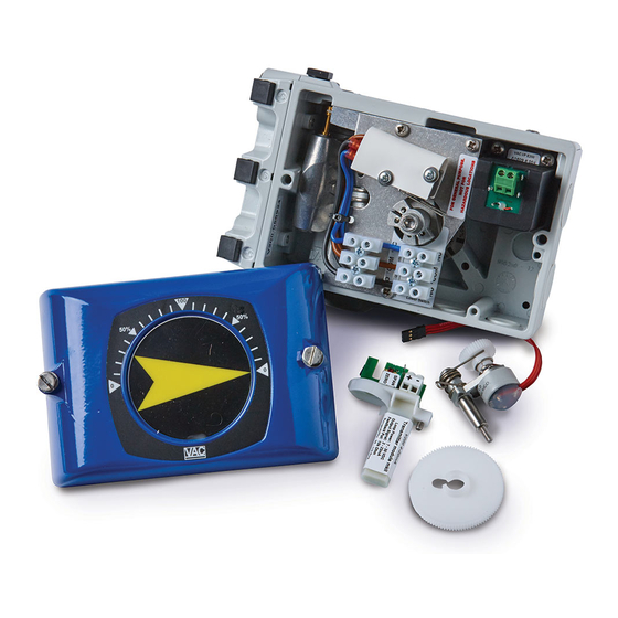
The V200 feedback options allows for accurate position feedback, where on-off (open/closed) indication (switches) or continuous 4-20mA transmission (or simple potentiometer) is required. Any feedback module can be factory or field installed inside the V200 positioner housing with no special parts or mounting brackets. This creates a very compact and simple package that is completely sealed. The various feedback options are connected to the... -
Page 4: Feedback Installation
V200 POSITIONER www.vac.se 2. FEEDBACK INSTALLATION 2.1 Connections – Grounding point 1. – Terminal block, switches 2 X 3 Connections Maximum cable size AWG 11 (4 mm 2. – Terminal block, Position Transmitter Maximum cable size AWG 13 (2.5 mm 2.2 Front cover and indicator 2.2.1 Removing the front cover Loosen the two screws(1) and remove the front cover. -
Page 5: 4-20Ma Transmitter Installation
V200 POSITIONER www.vacaccessories.com 2.3 4-20mA transmitter installation 2.3.1 Gearwheel installation 1. Remove the front cover and indicator on the V200 positioner. (see page 4) 2. Remove Indicator screw(1). 3. Install the gearwheel(2) so that it aligns over the cam locking nut screw(3). 4. Secure the gearwheel with the Indicator screw(1). 2.3.2 Potentiometer installation 1. Install the potentiometer module(4) in the designed section of the unit as shown. Tighten the screw that secures the pot arm and spring. -
Page 6: 4-20Ma Transmitter Setup
V200 POSITIONER www.vac.se 2.3.3 4-20mA transmitter setup The Position Transmitter is shipped for direct (CCW) turning, range 0-90° Determine the direction for increasing mA output. Direct (CCW) or Reverse (CW). The direction of rotation is simply determined by watching the positioner drive shaft(1). CCW rotation: the potentiometer lead connector(2) fitted with the Black or Blue colored lead facing to the left. -
Page 7: 4-20Ma Transmitter Calibration
V200 POSITIONER www.vacaccessories.com 2.3.5 4-20mA transmitter Calibration Make sure V200E/P has first been properly calibrated! 1. Power up the current loop. Pot adjustment.eps 2. Connect a low ohmic ampere meter over the test points(5). 3. Set the valve/actuator to the closed/zero position (4mA). 4. Turn the feedback potentiometer shaft(6) with a screw driver until you read 3.7 - 3.9 mA on the meter. 5. Adjust the trim potentiometer(7) marked zero so that the meter reads 4mA. -
Page 8: Trouble Shooting - Reset And Calibration
V200 POSITIONER www.vac.se 2.3.6 Trouble shooting - Reset and Calibration If you are unable to properly zero and span the feedback, the potentiometers could be out of factory settings. In order to get back to factory settings please follow the steps 1-8 below. -
Page 9: Switch Option Installation
V200 POSITIONER www.vacaccessories.com 2.4 Switch option Installation 2.4.1 Switch and cam installation 1. Remove the front cover and indicator on the V200 positioner. (see page 4) 2. Remove the Indicator screw(1). 3. Install the switch cam assembly(2) in the positioner drive slot and secure the cams with screw(3). Install the switch module(4) and tighten the three screws(5). 2.4.2 Electrical installation Connect your control system/equipment cables to the terminal blocks(6) Maximum cable size AWG 11(4 mm 2.4.3 Switch calibration... -
Page 10: Spare Parts
V200 POSITIONER www.vac.se 3. SPARE PARTS 3.1 Exploded drawing Feedback options 92077r14... -
Page 11: Spare Parts List Feedback Options
V200 POSITIONER www.vacaccessories.com 3.2 Spare parts list Feedback options Item Description Material Part no Item Description Material Part no 1 ..V200 Feedback Potentiometer 10K Kit ......93006 ....1 4 ..V200 Feedback Inductive Sensor Kit ......93014 ....1 (1 ..V200 Feedback Potentiometer 5K Kit ......93028 .... 1) 1 .. -
Page 12: Specifications
V200 POSITIONER www.vac.se 4. SPECIFICATIONS 4.1 Specifications feedback options Mechanical Switch module Type: SPDT, V3 (Camden CMNS 2020D) Maximum load: Resistive (Inductive) Voltage 10 A (3) A 250 VAC Reed Switch module Type: SPDT-CO, Form C (Hamlin 59145-3S02A) Contact rating: max 3W Voltage switching: max 175 VDC Voltage breakdown: min 200 VDC Current switching max 0.25 A...
Need help?
Do you have a question about the V200 POSITIONER and is the answer not in the manual?
Questions and answers