Table of Contents
Advertisement
Quick Links
Advertisement
Table of Contents

Subscribe to Our Youtube Channel
Related Manuals for PCB Piezotronics ICP 483C30


Summary of Contents for PCB Piezotronics ICP 483C30
- Page 1 Model 483C50 ICP® Sensor Signal Conditioner Installation and Operating Manual For assistance with the operation of this product, contact PCB Piezotronics, Inc. Toll-free: 800-828-8840 24-hour SensorLine: 716-684-0001 Fax: 716-684-0987 E-mail: info@pcb.com Web: www.pcb.com...
- Page 2 Piezotronics, user servicing or repair is critical test. not recommended and, if attempted, may void the factory warranty. Routine PCB Piezotronics maintains an ISO- maintenance, such as the cleaning of 9001 certified metrology laboratory and electrical connectors, housings, and offers calibration services, which are...
- Page 3 E-mail: info@pcb.com representative. Warranty – All equipment and repair services provided by PCB Piezotronics, Inc. are covered by a limited warranty against defective material workmanship for a period of one year from date of original purchase. Contact...
- Page 4 PCB工业监视和测量设备 - 中国RoHS2公布表 PCB Industrial Monitoring and Measuring Equipment - China RoHS 2 Disclosure Table 有害物质 汞 镉 六价铬 (Cr(VI)) 多溴联苯 (PBB) 多溴二苯醚 (PBDE) 部件名称 铅 (Pb) (Hg) (Cd) 住房 PCB板 电气连接器 压电晶体 环氧 铁氟龙 电子 厚膜基板 电线 电缆 塑料 焊接...
- Page 5 Component Name Hazardous Substances Lead Mercury Cadmium Chromium VI Polybrominated Polybrominated (Pb) (Hg) (Cd) Compounds Biphenyls Diphenyl (Cr(VI)) (PBB) Ethers (PBDE) Housing PCB Board Electrical Connectors Piezoelectric Crystals Epoxy Teflon Electronics Thick Film Substrate Wires Cables Plastic Solder Copper Alloy/Brass This table is prepared in accordance with the provisions of SJ/T 11364.
- Page 6 Manual # 34896 Rev. A PCB PIEZOTRONICS, INC. 3425 WALDEN AVENUE DEPEW, NY 14043-2495 PHONE 716-684-0001 FAX 716-684-0987 ® ICP is a registered trademark of PCB Group, Inc.
-
Page 7: Table Of Contents
Table of Contents Table of Contents Table of Figures 1-0. INTRODUCTION AND SPECIFICATIONS 1-1. Introduction: Safety Considerations 1-2. System Description, Basic Configuration ® 1-2.1. Input/Output Mode, All Models 1-3. Block Diagram 1-4. Installation 1-4.1. Grounding Techniques 1-5. Operation: Standard AC Line 1-6. -
Page 8: Table Of Figures
MODELS 483C30, 483C50 AND, 482M179 GENERAL OPERATION MANUAL 3-4. Unit Initialization Procedure 3-5. Command Summary 3-6. Command Format 3-7. Multiple Board Models 3-8. Commands GAIN SENS FSCI FSCO INPT IEXC OFLT OSCL RTED ALLC RBIA STUS UNIT UNID LEDS RSET AUTR SAVS WTED... - Page 9 MODELS 483C30, 483C50 AND, 482M179 GENERAL OPERATION MANUAL Figure 5 Selectable Gain Amplifier Configuration ...........5 Figure 6 Autoscale/Overload Window Comparator ..........7...
-
Page 10: Introduction And Specifications
WARNING 2: This equipment is designed with user safety in mind; however, the protection provided by the equipment may be impaired if the equipment is used in a manner not specified by PCB Piezotronics, Inc. Caution 1: Cables can kill your equipment. High voltage ElectroStatic Discharge (ESD) can damage electrical devices. -
Page 11: System Description, Basic Configuration
MODELS 483C30, 483C50, 482M179 AND 483M217 GENERAL OPERATION MANUAL EQUIPMENT RATINGS For complete specifications, please refer to the enclosed Specification Sheet. This equipment operates optimally at +32 to +120°F (0 to +50°C), in an environment having <85% relative humidity. These models require 100 to 240 VAC / 47 to 63 Hz to operate. In turn, they supply 24 VDC 2 to 20 mA, excitation to connected ICP®... -
Page 12: Block Diagram
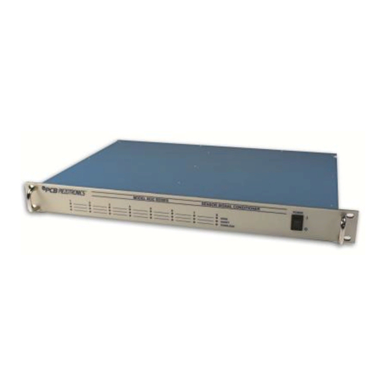
MODELS 483C30, 483C50, 482M179 AND 483M217 GENERAL OPERATION MANUAL 1-3. Block Diagram Figure 1 Typical Block Diagram 1-4. Installation These signal conditioner models comes in a standard 19-inch rack mount enclosure with a 1U (1.75”) height. The enclosure should be located in such a way as to allow convenient access to the power outlet for disconnect purposes. Since these models have low power consumption, they can be located in confined environments. -
Page 13: Operation: Standard Ac Line
MODELS 483C30, 483C50, 482M179 AND 483M217 GENERAL OPERATION MANUAL other grounds in the signal conditioner. This removes one of the grounds in the measurement channel and in most cases it will eliminate ground loops on that channel. 1-5. Operation: Standard AC Line Plug the line cord into a 120V/60 Hz or 230V/50 Hz power source and toggle the “ON/OFF”... -
Page 14: Input Fault Detection
MODELS 483C30, 483C50, 482M179 AND 483M217 GENERAL OPERATION MANUAL 2-3. Input Fault Detection These models monitor two input fault conditions; “short” and “open,” which indicate problems with sensor input and is displayed through the front panel LEDs. Either case implies that the sensor is NOT functioning properly. An input is shorted when it has a ground path for the sensor excitation and open when the sensor fails to draw the excitation. -
Page 15: 2-5.1. Programmable Gain
MODELS 483C30, 483C50, 482M179 AND 483M217 GENERAL OPERATION MANUAL 2-5.1. Programmable Gain Adjustable incremental gain (from 0.1 to 200) is standard in these models. The steps in the incremental gain are 0.1. This is particularly useful in the standardization of groups of sensors. Consider the following example, wherein the user desires to normalize sensitivities to 1 V/unit for each channel. -
Page 16: 2-7.1. Autoscaling
MODELS 483C30, 483C50, 482M179 AND 483M217 GENERAL OPERATION MANUAL 2-7.1. Autoscaling To avoid overload, these signal conditioners feature autoscaling for gain adjustment. It first sets maximum gain on all channels, then decreases the gain setting of any channel on which an overload has occurred. The gain autoscale continues until there is no overload with respect to the preset overload threshold level (standard ±10 volts) and sensed signal of the channel. -
Page 17: Non-Volatile Memory
MODELS 483C30, 483C50, 482M179 AND 483M217 GENERAL OPERATION MANUAL 2-9. Non-Volatile Memory This feature provides a mechanism to save and restore a programmed configuration. The programmable settings are saved when the unit receives a SAVS command and restored when the unit powers up. The unit’s non-volatile memory may be reset to the factory default settings by using the RSET Command. -
Page 18: Input Filtering
MODELS 483C30, 483C50, 482M179 AND 483M217 GENERAL OPERATION MANUAL 2-11.2 Input Filtering The Model 482C can also be ordered with low pass or high pass Input Filters installed. Input filters are located at the front end of the signal path, before any gain has been applied. This location may be advantageous for applications where gain is used and there is significant signal content outside the passband which could overload the signal conditioner. -
Page 19: Computer Interface Programming Guide
MODELS 483C30, 483C50, 482M179 AND 483M217 GENERAL OPERATION MANUAL 3-0. COMPUTER INTERFACE PROGRAMMING GUIDE 3-1. Introduction Individual commands are subject to feature availability on the particular unit. The Ethernet Interface enables these models to be fully controlled by a computer or handheld controller. With this interface, the unit is able to become part of a fully automated system. - Page 20 MODELS 483C30, 483C50, 482M179 AND 483M217 GENERAL OPERATION MANUAL • Now you can use the assigned IP address to address the unit. Important Note: The communication protocol requires a unit id as part of the command header. The unit id is not the IP address.
- Page 21 MODELS 483C30, 483C50, 482M179 AND 483M217 GENERAL OPERATION MANUAL Following this screen the right panel will appear as shown below. Click on the ‘Connection’ item and check to see that the parameters are shown as below and pay particular attention to the ‘Active Connection’ and ‘Endpoint’ Port items. They should be set as shown below.
- Page 22 MODELS 483C30, 483C50, 482M179 AND 483M217 GENERAL OPERATION MANUAL...
- Page 23 MODELS 483C30, 483C50, 482M179 AND 483M217 GENERAL OPERATION MANUAL...
-
Page 24: Communication Guidelines
MODELS 483C30, 483C50, 482M179 AND 483M217 GENERAL OPERATION MANUAL 3-3. Communication Guidelines 1) Data transfer from the host terminal to the unit must contain an ending delimiter of <CR><LF>. Example: <CR><LF> -Carriage Return and Line feed. (In ASCII, <CR> is 13; <LF> is 10.) 2) The number of characters for any command string, from the first character to the <CR>, may not exceed 255. -
Page 25: Command Format
MODELS 483C30, 483C50, 482M179 AND 483M217 GENERAL OPERATION MANUAL Command type definitions; • R/W – the setting can be read from or written to the unit or channel. • R – The information can only be read from the unit or channel. •... - Page 26 MODELS 483C30, 483C50, 482M179 AND 483M217 GENERAL OPERATION MANUAL Likewise, a global Query command will be responded to by the channel 1-4 board but will be ignored by the channel 5-8 board. However, in order to facilitate efficient communications with the second board, the concept of a second unit address was introduced.
- Page 27 MODELS 483C30, 483C50, 482M179 AND 483M217 GENERAL OPERATION MANUAL Global Gain Query: 1:0:SENS? Global Gain Response: 1:SENS:1= 6.0;2= 10.0;3= 10.0;4= 10.0; FSCI The FSCI command provides a scaling mechanism to automatically set the gain based on a known input level (in EU) and what output level (in Volts) you would like that Full Scale input level to be represented by.
-
Page 28: Inpt
MODELS 483C30, 483C50, 482M179 AND 483M217 GENERAL OPERATION MANUAL • ® • Multi-Charge option of 10mV/pc sensitivity • Multi-Charge option of 1.0mV/pc sensitivity • Multi-Charge option of 0.1mV/pc sensitivity • ® Isolated ICP • Isolated Multi-Charge option of 10mV/pc sensitivity 7 •... - Page 29 MODELS 483C30, 483C50, 482M179 AND 483M217 GENERAL OPERATION MANUAL Global IEXC Query: 1:0: IEXC? Global IEXC Response: 1:IEXC:1=4; OFLT The OFLT command enables or disables the Output Filter. The Output Filter value is sent as an integer value of either 0 -Disable or 1-Enable. Setting: 2:1:OFLT= 1\r\n ( unit 2, channel 1, Output Filter Enabled ) Setting Response: 2: OFLT:ok...
- Page 30 MODELS 483C30, 483C50, 482M179 AND 483M217 GENERAL OPERATION MANUAL RTED The RTED query returns the TEDS information that is stored in the sensor or other, TEDS capable, in-line module attached to a specific channel. The signal conditioners are IEEE 1451.4 compliant in that they will read the family code of the 1-wire memory chip to determine its type.
- Page 31 MODELS 483C30, 483C50, 482M179 AND 483M217 GENERAL OPERATION MANUAL RBIA The RBIA command is used to read all channels Bias Levels. Setting: N/A – Command is Read only Query: This command is a global command and will return all channel bias readings regardless of the channel id in the command.
- Page 32 MODELS 483C30, 483C50, 482M179 AND 483M217 GENERAL OPERATION MANUAL Query: 1:1:UNIT? Response: 1:UNIT:482C\s\s\s\s\s\s\s\s\s\s\s\s:FW\sVer\s1.0:12345:09-27-2006:10.000:1:4:1:16,37,1,143,0\r\n Model & Firmware version strings are self-explanatory. Following are: Serial Number (U16): Cal Date (10 character string): Filter corner (kHz) Unit Id: Number of Channels: Starting Channel Number Followed by the option bytes: Gain Options OPT_GAIN_INC...
- Page 33 MODELS 483C30, 483C50, 482M179 AND 483M217 GENERAL OPERATION MANUAL LEDS The LEDS command is used to test the LED functionality of the front panel. When sent as a command the LED’s on the front panel will flash 3 times. This command invokes a function and therefore has no query capability.
- Page 34 MODELS 483C30, 483C50, 482M179 AND 483M217 GENERAL OPERATION MANUAL Query Format: Unit#:Ch#: AUTR? Response format: Unit#:Cmd:Ch#:=current state (0=off,1-on,2=immediate) Query: 2:1:AUTR? Query Response: 2:AUTR:1=0; SAVS The SAVS command is used to store the current channel setting as the default settings that will be restored on power up.
-
Page 35: Communication Responses
MODELS 483C30, 483C50, 482M179 AND 483M217 GENERAL OPERATION MANUAL Command interpretation: Unit=1;channel=1;’WTED=’; 36 = bytes in the message payload (values after the ‘=’ sign);0 = DO NOT write to the application register if it exists; 0 = write to page 0; 23-117 are the 32 bytes to be written into the TEDS chip EEPROM memory;... - Page 36 Model Number Revision: H ICP® SENSOR SIGNAL CONDITIONER 483C50 ECN #: 45020 Performance ENGLISH OPTIONAL VERSIONS Channels Optional versions have identical specifications and accessories as listed for the standard Sensor Input Type(s) ICP®, Voltage ICP®, Voltage model except where noted below. More than one option may be used. Voltage Gain x0.1 to x200 x0.1 to x200...
- Page 37 PCB Piezotronics Inc. claims proprietary rights in REVISIONS the information disclosed hereon. Neither it nor any reproduction thereof will be disclosed to others DESCRIPTION without the written consent of PCB Piezotronics Inc. RELEASED TO DRAFTING 43807 16X BNC CONNECTORS EXTERNAL AC POWER...
Need help?
Do you have a question about the ICP 483C30 and is the answer not in the manual?
Questions and answers