Table of Contents
Advertisement
Available languages
Available languages
Quick Links
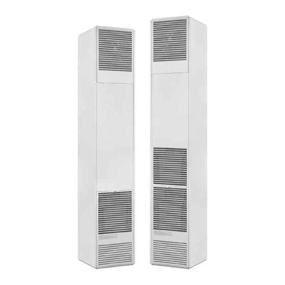
NATURAL GAS - DVCF403C - H, DVCF553C - H, DVCF407C-H, DVCF557C-H
PROPANE GAS - DVCF404C-H, DVCF554C-H, DVCF408C-H, DVCF558C-H
!
WARNING: If the information in these instructions
is not followed exactly, a fire or explosion may result
causing property damage, personal injury or loss of life.
— Do not store or use gasoline or other flammable vapors and
liquids in the vicinity of this or any other appliance.
— WHAT TO DO IF YOU SMELL GAS
• Do not try to light any appliance.
• Do not touch any electrical switch; do not use any phone
in your building.
• Immediately call your gas supplier from a neighbor's
phone. Follow the gas supplier's instructions.
• If you cannot reach your gas supplier, call the fire
department.
— Installation and service must be performed by a qualified
installer, service agency or the gas supplier.
INSTALLER: Leave this manual with the appliance.
CONSUMER: Retain this manual for future reference.
WARNING: This product can expose you to chemicals including epichlorohydrin
!
which is known to the State of California to cause cancer and birth defects and/or
other reproductive harm. For information go to www.p65warnings.ca.gov.
- The coating selected to provide longer life to the heat exchanger may smoke slightly upon initial firing. Please provide adequate
ventilation if this occurs.
- Installation, maintenance, service, troubleshooting & repairs must be performed by a qualified service agency. DO NOT attempt any of
these procedures if you are not qualified as this could expose you to property damage, personal injury, or loss of life and will invalidate
all warranties.
- This unit is for residential use only and is not approved for installation in greenhouses, or environments involving dusty, wet, corrosive,
or explosive conditions. Such conditions will invalidate the warranty and may create unsafe conditions.
- The appliance may be installed in an aftermarket permanently located, manufactured home (USA only) or mobile home, where not
prohibited by local codes. This appliance is only for use with the type of gas indicated on the rating plate. This appliance is not
convertible for use with other gases, unless a certified kit is used.
WARNING: Operation of this furnace without the properly installed, furnished vent system and vent cap could result in Carbon
Monoxide (CO) poisoning and possible death. For your safety, this furnace and the vent system should be inspected at least
annually by a qualified service technician.
Cozy Heating Systems, LLC | cozyheaters.com | 888-444-1212 | 250 West Laurel Street | Colton, CA 92324
Installation and Operating Instructions
DIRECT VENT
COUNTERFLOW
WALL FURNACE
!
alteration, service or maintenance can cause
injury or property damage. Refer to this manual
for proper installation. For assistance or for
additional information consult a qualified installer,
service agency or the gas supplier.
Page 1
DVCF55
DVCF40
WARNING: Improper installation, adjustment,
1018028-B
Advertisement
Chapters
Table of Contents

Related Manuals for COZY DVCF40


Summary of Contents for COZY DVCF40
- Page 1 Monoxide (CO) poisoning and possible death. For your safety, this furnace and the vent system should be inspected at least annually by a qualified service technician. Cozy Heating Systems, LLC | cozyheaters.com | 888-444-1212 | 250 West Laurel Street | Colton, CA 92324 Page 1...
-
Page 2: Table Of Contents
CONTENTS READ CAREFULLY BEFORE INSTALLING UNIT Before Installation These installation instructions are a general guide and do not supersede applicable local codes and ordinances. Before planning Standards ........... 2 or making the installation be sure it complies with all phases of the Specifications ........ -
Page 3: Specifications
SPECIFICATIONS & DIMENSIONS Your Direct Vent Counterflow Wall Furnace is shipped in two cartons. One carton contains the furnace, thermostat, thermostat wire and insulated staples. The second carton will have the vent tube, air intake tube and vent cap assembly. After the furnace has been removed from the carton check the rating plate to verify that the model number is correct and that the wall furnace is equipped with the type gas you intend to use. -
Page 4: Venting
SAFETY - Continued technician. The furnace should be inspected before use and 17. Do not use this heater if any part has been under water. at least annually by a professional service technician. More Immediately call a qualified service technician to inspect the heater and to replace any part of the control system which frequent cleaning may be required due to excessive lint from has been under water. -
Page 5: Clearances
= Area where terminal is not permitted CANADIAN U.S. INSTALLATIONS** REFERENCE LETTER TO DRAWING INSTALLATIONS* DVCF40 DVCF55 A Clearance above grade, veranda, porch, deck, or balcony 12 Inches (30 cm) 12 Inches (30 cm) B Clearance to window or door that may be opened 12 Inches (30 cm) 9”... - Page 6 CLEARANCES - Continued 1. MINIMUM CLEARANCES FIG. 1 CEILING • Side Wall: Min. Clearance = 4” 4” Minimum (See Fig. 1) NOTE: The unit may be recessed and rest directly against side studs and the inside surface of the rear wall. •...
-
Page 7: Locations
ROUGH-IN GAS SUPPLY Install a 1/2 inch diameter gas supply line. The gas line can enter the cabinet through the right side or bottom (See Figure 3). The gas line DVCF40 - 59” WALL DVCF55 - 68-1/2” must have an individual manual shut off valve. Also, you must install a STUDS drip leg and provide a 1/8”... -
Page 8: Locate Vent Opening
INSTALLATION FIG. 6 LOCATE VENT OPENING OUTSIDE WALL INSIDE After the location of the heater has been determined, the opening for the vent pipe should be cut. If the heater is to be recessed, cut “ ” out opening for heater between studs on the interior wall and cut out the floor plate between the studs, so heater will set flat on floor as all dimensions are given from a finished floor. -
Page 9: Lighting Instructions
LIGHTING INSTRUCTIONS MODELS: DVCF403C-H / DVCF404C-H / DVCF553C-H / DVCF554C-H FOR YOUR SAFETY READ BEFORE LIGHTING WARNING: This appliance has a pilot which must be • If you cannot reach your gas supplier, call If you do not lighted by hand. When lighting the pilot, the fire department. - Page 10 LIGHTING INSTRUCTIONS MODELS: DVCF407C-H / DVCF408C-H / DVCF557C-H / DVCF558C-H FOR YOUR SAFETY READ BEFORE LIGHTING WARNING: This appliance is equipped with an ignition • If you cannot reach your gas supplier, call If you do not device which automatically lights the pilot. the fire department.
-
Page 11: Maintenance
MAINTENANCE WARNING: This is a gas-fired appliance. Keep the area clear of gasoline and other flammable vapors and liquids. All combustible material must be kept clear of this area to avoid fire or explosion. For proper and safe operation, keep furnace and furnace area clean. At regular intervals turn control valve off, let cool and clean inside control compartment. -
Page 12: Wiring Diagrams
MAINTENANCE TO REMOVE MAIN BURNER PROPER BURNER FLAME FOR INSPECTION & CLEANING The burner flame may be observed by raising the sight glass cover. A proper Turn thermostat to lowest setting and allow flame will have a dark blue inner mantle that sits right on top of the burners with the furnace to cool. - Page 13 WIRING SCHEMATICS Standing Pilot Models IID Models PICTORIAL SCHEMATIC Models Amps DVCF407C-H . . . . . . . . . . . . . 2 .20 DVCF408C-H .
- Page 14 Plug power cord into wall receptacle. Light the heater following lighting instructions. BOTTOM SECTION (4) MODEL NO. LENGTH OF BOTTOM SECTION (Ref. 4) PLASTIC RACEWAY DVCF40 5-5/16 Inches NOTE: Lengths terminate approximately 2 inches above floor. DVCF55 14 Inches NOTE: Lengths terminate approximately 2 inches above floor.
-
Page 15: 31300-A Cabinet Trim Kit
31300-A: CABINET TRIM KIT CAUTION: These kits must be installed by a qualified installer or service technician. FIG. 12-A PART DESCRIPTION QUANTITY PART NO. 48” Long Side Flange ......Qty. 4 31310 15-1/2”... -
Page 16: Side Discharge Kits
306SR & 30SRB: SIDE DISCHARGE KITS (Optional Accessories) CAUTION: These kits must be installed by a qualified installer or service technician. 306SR-A 30SRB-A Side Discharge on Casing Side Discharge with Extension Boot Cut out and remove embossed area on Cut opening in drywall as shown in figure 11, below. casing side. - Page 17 TROUBLESHOOTING CHART ( For Qualified Service Technician ) - MAIN BURNER Please follow the following corrective actions in order. SYMPTOM POSSIBLE CAUSES CORRECTIVE ACTION Flame Too 1. Defective operator section of valve. 1. Replace valve. Large 2. Burner orifice too large. 2.
-
Page 18: Installations In The State Of Massachusetts
TROUBLESHOOTING CHART ( For Qualified Service Technician ) - MAIN BURNER Please follow the following corrective actions in order. SYMPTOM POSSIBLE CAUSES CORRECTIVE ACTION Burner Won’t 1. Gas valve not turned on. Turn gas valve to “on” position. Turn On 2. - Page 19 TROUBLESHOOTING CHART ( Specifically for Intermittent Ignition System ) - IID Please follow the following corrective actions in order. GREEN LED FLASH INDICATES NEXT SYSTEM ACTION RECOMMENDED SERVICE ACTION CODE (XxY)ª No Call for Heat Not Applicable None Not Applicable None Flash Fast Startup - Flame...
- Page 20 - Serial Number contact the wholesaler from which you - Type of Gas Used purchased your Cozy heater. This information can be found on the rating plate that is attached to the heater. NOTE: Parts & schematic drawings on current models are shown at: cozyheaters.com | Specifications subject to change without notice.
- Page 21 Aux. Limit Switch, 60T15-L350 78086 78086 78086 78086 Transformer 78069 78069 78069 78069 Transformer Plate 34089 34089 34089 34089 Cozy Handle 84003 84003 84003 84003 Wiring Harness 72251 72252 72253 72250 Terminal Board 78300 78300 78300 78300 Flue Outlet Pipe Gasket - 7” Circle...
- Page 22 - Serial Number contact the wholesaler from which you - Type of Gas Used purchased your Cozy heater. This information can be found on the rating plate that is attached to the heater. NOTE: Parts & schematic drawings on current models are shown at: cozyheaters.com | Specifications subject to change without notice.
- Page 23 DIRECT VENT COUNTERFLOW WALL FURNACE PARTS LIST Natural Gas: DVCF403C-H, DVCF553C-H, DVCF407C-H, DVCF557C-H Propane Gas: DVCF404C-H, DVCF554C-H, DVCF408C-H, DVCF558C-H DVCF403C-H DVCF407C-H DVCF553C-H DVCF557C-H Natural Gas Model Numbers ......DVCF404C-H DVCF408C-H DVCF554C-H...
- Page 24 RIGHTS AND YOU MAY ALSO HAVE OTHER RIGHTS AND ARE IN LIEU OF ALL OTHER REMEDIES. WHICH VARY FROM STATE TO STATE. TO REGISTER YOUR FURNACE: GO ONLINE TO THE COZY HEATERS WEBSITE AT: www.cozyheaters.com/warranty-registration/ COZY HEATING SYSTEMS, LLC 250 WEST LAUREL STREET – COLTON, CA 92324...
- Page 25 Cozy Heating Systems, LLC | cozyheaters.com | 888-444-1212 | 250 West Laurel Street | Colton, CA 92324 Manual Español Página 1...
-
Page 26: Dvcf Part List
CONTENIDO LEA ESTA SECCIÓN ANTES DE INSTALAR LA UNIDAD Antes de la Instalación Este instructivo es una guía general para su aparato y no substituye los códigos y reglamentos locales que aplican. Antes de planear o Estándares ......... 2 realizar la instalación, asegúrese de que cumple con todas las fases Especificaciones y Dimensiones .. -
Page 27: Especificaciones Y Dimensiones
ESPECIFICACIONES Y DIMENSIONES Su calefactor a contra:flujo de pared con ventila directa fue enviado completo en dos cajas. Una caja contiene el calefactor, el termostato, el alambre para el termostato y grapas aislantes. La segunda caja contiene el tubo de la ventila, el tubo de entrada de aire y el ensamble de la tapa de la ventila. -
Page 28: Desfogue
REGLAS DE SEGURIDAD - Continuado 13. La instalación y la reparación se deben realizar por un técnico de 17. No use este aparato si alguna de sus partes ha estado bajo el agua. servicio calificado. El calefactor de pared debe ser inspeccionado De inmediato llame a un técnico calificado para que inspeccione el antes de ser usado y por lo menos una vez al año. -
Page 29: Espacios Libres
= Área Donde no se Permite el Terminal INSTALACIONES Instalaciones de EE.UU.** CARTA DE REFERENCIA AL DIBUJO CANADIENSES* DVCF40 DVCF55 A Holgadura sobre grado, veranda porche, cubierta, o balcón 30 cm (12”) 30 cm (12”) B Holgadura a ventana o puerta que pudiera estar abierta 30 cm (12”) - Page 30 ESPACIOS LIBRES - Continuado 1. DISTANCIAS MÍNIMAS FIG. 1 CEILO • Pared Lateral: El espacio mínimo = 10.16 cm 10.16cm Min. (Ver Ilustración 1) NOTA: La unidad puede ser empotrada y descansar directamente contra los entramos laterales y la superficie interna de la pared trasera.
-
Page 31: Ubicaciones
(Ver la Ilustración 3). La línea del gas debe tener una válvula individual de cierre manual. También, debe instalar un tubo de goteo en la línea DVCF40 - 149.86cm Entramados DVCF55 - 173.99cm de gas y dejar un tubo de prueba (conroscaytapón) de N.P.T. -
Page 32: Conexión De Gas
INSTALACIÓN COLOCACIÓN DE LA APERTURA PARA LA VENTILA FIG. 6 AFUERA PARED DENTRO Después de haber determinado la ubicación del calefactor, se debe hacer un orificio para el dueto de la ventila. Si el calefactor va a ser empotrado, corte la apertura para el calefactor entre los entramados de la pared interior y corte la “... -
Page 33: Instrucciones De Encendido
INSTRUCCIONES DE ENCENDIDO MODELOS: DVCF403C-H / DVCF404C-H / DVCF553C-H / DVCF554C-H PARA SU SEGURIDAD LEA ESTE INSTRUCTIVO ANTES DE ENCENDER EL APARATO ADVERTENCIA: Este aparato tiene un piloto que se debe instrucciones de la compañía de gas. encender a mano. Siga estas instrucciones •... - Page 34 INSTRUCCIONES DE ENCENDIDO MODELOS: DVCF407C-H / DVCF408C-H / DVCF557C-H / DVCF558C-H PARA SU SEGURIDAD LEA ESTE INSTRUCTIVO ANTES DE ENCENDER EL APARATO ADVERTENCIA: Este aparato está equipado con un dispositivo instrucciones de la compañía de gas. que enciende automáticamente el piloto. NO •...
-
Page 35: Mantenimiento
MANTENIMIENTO ADVERTENCIA: ESTE ES UN APARATO A GAS. Mantenga el área libre de gasolina y otros vapores y líquidos inflamables. Todo el material combustible debe mantenerse alejado de esta área para evitar incendios o explosiones. Para que su calefactor tenga un funcionamiento apropiado y seguro, mantenga límpio el calefactor y el área donde éste se encuentra A intervalos regulares, apague la válvula de control (colóquela en la posición OFF), deje TUBO que se enfríe y limpie la parte de adentro del compartimiento. - Page 36 MANTENIMIENTO CÓMO RETIRAR EL QUEMADOR PRINCIPAL AL REALIZAR LA INSPECCIÓN Y LIMPIEZA LLAMA APROPIADA DEL QUEMADOR Baje el termostato al valor más bajo y permita La llama del quemador se puede observar levantando la tapa del vidrio. Una llama que se enfríe el calefactor. apropiada deberá...
- Page 37 ESQUEMA DE CABLEADO Piloto Vertical Encendido Intermitente ESQUEMA DEL APARATO Modelos Amps DVCF407C-H . . . . . . . . . . . 2 .20 DVCF408C-H . . . . . . . . . . . 2 .25 DVCF557C-H .
-
Page 38: 14-Pek
15. Encienda el calefactor siguiendo las instrucciones de encendido. SECCIÓN INFERIOR (4) MODEL NO. LONGITUD DE LA PARTE INFERIOR (Ref. 4) DE LA SECCIÓN DE PLÁSTICO DVCF40 13.49 cm NOTA: Las longitudes anteriores terminan aproximadamente 5.08 cm sobre el piso. DVCF55 35.56 cm... -
Page 39: 31300-A
31300-A: KIT DE ACABADO DEL GABINETE PRECAUCIÓN: Este equipo se debe instalar por un instalador o un técnico de servicio calificados. FIG. 12-A NUM. DE PARTE DESCRIPCIÓN CANTIDAD PARTE JUEGO NRO. 31300-A Angulo Para Orilla Lateral del Gabinete ..Qty. 4 31310 JUEGO DE ORILLAS... -
Page 40: Kits De Descarga Lateral
306SR & 30SRB: KITS DE DESCARGA LATERAL (Accesorios Opcionales) PRECAUCIÓN: Este equipo se debe instalar por un instalador o un técnico de servicio calificados. 306SR-A 30SRB-A Descarga lateral en la carcasa Descarga lateral con arranque de extensión Recorte y quite el área repujada en el lado de Corte la abertura en paneles de yeso como se muestra en la figura 11, a la carcasa. - Page 41 TABLA DE LOCALIZACIÓN DE PROBLEMAS ( Para un Técnico de Servicio Calificados ) - QUEMADOR PRINCIPAL Por favor, siga las siguientes acciones correctivas en orden. SÍNTOMA CAUSAS POSIBLES ACCIÓN CORRECTIVA La Llama está 1. Sección defectuosa de la válvula. 1. Cambie la válvula. Muy Grande 2.
-
Page 42: Instalaciones En El Estado De Massachusetts
TABLA DE LOCALIZACIÓN DE PROBLEMAS ( Para un Técnico de Servicio Calificados ) - QUEMADOR PRINCIPAL Por favor, siga las siguientes acciones correctivas en orden. SÍNTOMA CAUSAS POSIBLES ACCIÓN CORRECTIVA El Quemador 1. La válvula del gas no está encendida. 1. - Page 43 TABLA DE LOCALIZACIÓN DE PROBLEMAS ( Especificamente Para el Piloto De Encendido Intermitente ) - IID Para un técnico de servicio calificados. CÓDIGO VERDE SIGUIENTE ACCIÓN INDICA ACCIÓN DE SERVICIO RECOMENDADA DE LED (XxY)ª DEL SISTEMA Apagado No hay “demanda de calor.” No Applica Ninguna Puesta en marcha -...
- Page 44 Para obtener un servicio de piezas -Tipo de gas utilizado rápido, comuníquese con el mayorista al que le compró su calentador Cozy. Esta información se puede encontrar en placa de características que está unida al calentador. NOTA: Las partes y los esquemas del modelo actual se publican en: cozyheaters.com | Las especificaciones están sujetas a cambios sin previo aviso.
- Page 45 Interruptor Limitador auxiliar, 60T15-LJSO 78086 78086 78086 78086 Transformador 78069 78069 78069 78069 Placa del transformador 34089 34089 34089 34089 Manivela Cozy 84003 84003 84003 84003 Arnés de alambrado 72251 72252 72253 72250 Tablilla de terminales 78300 78300 78300 78300...
- Page 46 Para obtener un servicio de piezas -Tipo de gas utilizado rápido, comuníquese con el mayorista al que le compró su calentador Cozy. Esta información se puede encontrar en placa de características que está unida al calentador. NOTA: Las partes y los esquemas del modelo actual se publican en: cozyheaters.com | Las especificaciones están sujetas a cambios sin previo aviso.
- Page 47 LISTA DE PIEZAS - CALEFACTORA CONTRAFLUJO DE PARED DE VENTILA DIRECTA Gas Natural: DVCF403C-H, DVCF553C-H, DVCF407C-H, DVCF557C-H Gas Propano: DVCF404C-H, DVCF554C-H, DVCF408C-H, DVCF558C-H Números de Modelo de Gas Natural ....DVCF403C-H DVCF407C-H DVCF553C-H...
-
Page 48: Garantía
VARIAR DE UN ESTADO A OTRO. duración de una garantía implícita, y algunos estados no permiten la exclusión o limitación de PARA REGISTRAR SU CALEFACTOR: Vaya en línea al sitio web de Cozy Heaters en: www.cozyheaters.com/warranty-registration/ COZY HEATING SYSTEMS, LLC 250 WEST LAUREL STREET –... - Page 49 à l’oxyde de carbone et possiblement la mort. Pour votre sûreté, l’appareil de chauffage et le système de ventilation devraient être inspectés au moins annuellement par un technicien d’entretien qualifié. Cozy Heating Systems, LLC | cozyheaters.com | 888-444-1212 | 250 West Laurel Street | Colton, CA 92324 Manuel Français...
- Page 50 TABLE DES MATIÉRES LIRE ATTENTIVEMENT AVANT D’INSTALLER DE CETTE L’UNITÉ Ces directives d’installation servent de guide général et ne remplacent Avant l’installation pas les codes locaux et ordonnances applicables. S’assurer de se Normes ..........2 confonner à toutes les phases du code de chauffage local avant Spécifications et dimensions ....
- Page 51 CARACTÉRISTIQUES ET DIMENSIONS Votre appareil de chauffage à circulation à contre courant et à ventilation directe est emballé et expédié en deux cartons. Un carton contient la fournaise, le fil de thermostat et les crampons isolés. L’autre carton contiendra le tuyau d’aération, le tube d’admission d’air et l’assemblage du chapeau de ventilation.
- Page 52 RÈGLES DE SÉCIOEUTÉ - A Continué 12. Ne pas placer de vêtement ou autre matériel inflammable sur ou de la largeur et de la profondeur de la chaudière. Si vous devez installer un kit de registre d’air latéral, reportezvous à la page 14. près de 1’...
- Page 53 = Secteur ou la Borne n’est pas Autorisée INSTALLATIONS Installations de ETATS-UNIS** LETTRE DE REFERENCE AU DESSIN CANADIENNES* DVCF40 DVCF55 A Le dégagement au-dessus du degré, la véranda. la porche, le 12 Pouces (30 cm) 12 Pouces (30 cm) pont. ou le balcon B Le dégagement à...
- Page 54 DÉGAGEMENTS - A Continué 1. DISTANCES MINIMALES FIG. 1 PLAFOND • Mur latéral: L’espace minimum = 10.16 cm 10,16 cm Minimum (Voir Illustration 1) REMARQUE: L’unité peut être encastrée et repose directement contre l’entrée latérale et la surface interne de la paroi arrière.
- Page 55 Le conduit de gaz doit avoir son propre robinet de fermeture manuelle.· Installer également un point de purge et fournir une dérivation filetée NPT de 1/8 pouce, accessible pour adapteur de manomètre d’essai, DVCF40 - 149.86cm Poteaux DVCF55 - 173.99cm inunédiatement en amont du raccordement d’alimentation de gaz à...
- Page 56 INSTALACIÓN SITUER L’OUVERTURE DE VENTILATION FIG. 6 À L’EXTÉRIEUR À L’INTÉRIEUR Une fois que l’emplacement de l’appareil de chauffage a été determine, il faut couper l’ouverture du tuyau de ventilation. Si l’appareil doit être encastré, couper l’ouverture entre les poteaux sur le mur intérieur et couper “...
- Page 57 INSTRUCTIONS D’ALLUMAGE MODÈLES: DVCF403C-H / DVCF404C-H / DVCF553C-H / DVCF554C-H PAR SOUCI DE SÉCURITÉ, LIRE AVANT D’ALLUMER Cet appareil est équipé d’une veilleuse qui doit être Suivre les directives du fournisseur de gaz. MISE EN allumée manuellement. Suivre scrupuleusement • Si votre fournisseur de gaz n’est pas disponible, GARDE: les consignes lors de l’allumage de la veilleuse.
- Page 58 INSTRUCTIONS D’ALLUMAGE MODÈLES: DVCF407C-H / DVCF408C-H / DVCF557C-H / DVCF558C-H PAR SOUCI DE SÉCURITÉ, LIRE AVANT D’ALLUMER appareil muni d’un dispositif Suivre les directives du fournisseur de gaz. MISE EN d’allumage qui allume automatiquement la • Si votre fournisseur de gaz n’est pas disponible, veilleuse.
- Page 59 ENTRETIEN MISE EN GARDE: CET APPAREIL FONCTIONNE AU GAZ. Ne pas entreposer ou utiliser de l’essence ou d’autres liquides ou vapeurs inflammables aux alentours de cet appareil. Toute matière combustible doit être gardée loin de cet appareil de chauffage afin d’éviter une incendie ou une explosion. Garder propres la fournaise et l’aire de la fournaise pour un fonctionnement sûr et approprié.
- Page 60 ENTRETIEN COMMENT ENLEVER LE BRÛLEUR PRINCIPAL POUR INSPECTION ET NETTOYAGE FLAMME APPROPRIÉE DU BRÛLEUR Régler le thermostat au point le plus bas et laisser On peut observer la flamme du brûleur en soulevant la plaque-couvercle du voyant. Une l’appareil de chauffage refroidir. flamme appropriée aura un manteau interne bleu foncé...
- Page 61 SCHÉMA DE CÂBLAGE Veilleuse Constante Veilleuse IID SCHÉMA Modeles Amps DVCF407C-H . . . 2 .20 DVCF408C-H . . . 2 .25 DVCF557C-H . . . 3 .30 DVCF558C-H . . . 3 .35 Voir page 22 pour un schéma plus...
- Page 62 15. Mettre l’appareil de chauffage en marche en suivant les instructions d’allumage. SECTION DU BAS (4) No. de Modèle LONGUEUR DE LA SECTION DU BAS (Réf 4) CANALISATION PLASTIQUE DVCF40 13,49 cm REMARQUE: Les longueurs ci-dessus se terminent à environ 5,08 cm au-dessus du plancher. DVCF55 35,56 cm REMARQUE: Les longueurs ci-dessus se terminent à...
- Page 63 31300-A: TROUSSE DE GARNITURE DE CABINET ATTENTION: Ce kit doit être installé par un installateur qualifié ou un technicien de maintenance. FIG. 12-A DESCRIPTION DE PIÈCES QUANTITÉ No. PIÈCE N° D’ENSEMBLE Angle de Garniture du Côté du Cabinet ..Qty. 4 31310 31300-A ENSEMBLE...
- Page 64 306SR & 30SRB: ENSEMBLES DE DÉCHARGE LATÉRALE (Accesorios Opcionales) ATTENTION: Ce kit doit être installé par un installateur qualifié ou un technicien de maintenance. 306SR-A 30SRB-A Décharge Latérale sur le Caisson DÉCHARGE LATÉRALE (avec pièce de prolongement) Couper et retirer la partie enstampée sur le Couper l’ouverture dans la cloison sèche comme montré...
- Page 65 TABLEAU DE DEPANNAGE ( Par un Installateur Qualifié ou un Technicien de Maintenance ) - BRÛLEUR PRINCIPAL Veuillez suivre les actions correctives suivantes dans l’ordre. PROBLÈME CAUSE POSSIBLE ACTION CORRECTIVE Flamme 1. Soupape defective. 1. Remplacer la soupape. Trop Grande 2.
- Page 66 TABLEAU DE DEPANNAGE ( Par un Installateur Qualifié ou un Technicien de Maintenance ) - BRÛLEUR PRINCIPAL Veuillez suivre les actions correctives suivantes dans l’ordre. PROBLÈME CAUSE POSSIBLE ACTION CORRECTIVE Le Brûleur ne 1. La soupape à gaz pas ouverte. 1.
- Page 67 TABLEAU DE DEPANNAGE ( Spécifiquement Pour la Veilleuse Intermittente ) - IID A utiliser par un installateur ou un technicien d’entretien qualifié. CODE PROCHAINE ACTION INTERVENTION D’ENTRETIEN CLIGNOTANT LED INDIQUE DU SYSTÈME RECOMMANDÈE VERT (XxY)ª Eteinte Aucun «beso in de chaleur» Non applicable Aucune Démarrage - Détection de la...
- Page 68 Cette information peut être trouvée sur la plaque signalétique acheté votre appareil de chauffage Cozy. qui est attachée à l’appareil de chauffage. NOTE: Les parties et diagrammes du modèle actuel sont publiés dans: cozyheaters.com | Les spécifications sont sujettes à changement sans préavis.
- Page 69 Commutateur Auxiliaire de Seuil, 60T15-LJS0 78086 78086 78086 78086 Transformateur 78069 78069 78069 78069 Raque du Transformateur 34089 34089 34089 34089 Poignee Cozy 84003 84003 84003 84003 Gables groupes 72251 72252 72253 72250 Raque a bornes 78300 78300 78300 78300...
- Page 70 Cette information peut être trouvée sur la plaque signalétique acheté votre appareil de chauffage Cozy. qui est attachée à l’appareil de chauffage. NOTE: Les parties et diagrammes du modèle actuel sont publiés dans: cozyheaters.com | Les spécifications sont sujettes à changement sans préavis.
- Page 71 LISTE DES PIÈCES - CHAUFFE-CAISSE MURALE À VENTILATION DIRECTE Gaz Naturel: DVCF403C-H, DVCF553C-H, DVCF407C-H, DVCF557C-H Gaz Propane: DVCF404C-H, DVCF554C-H, DVCF408C-H, DVCF558C-H Numéros de Modèle de Gaz Naturel ....DVCF403C-H DVCF407C-H DVCF553C-H...
- Page 72 PEUT ETRE D’AUTRES DROITS VARIANT SELON RECOURS POSSIBLE POUR L’UTILISATEUR VOTRE PAYS POUR ENREGISTRER VOTRE FOURNAISE : Allez en ligne sur le site Web de Cozy Heaters à l’adresse : www.cozyheaters.com/warranty-registration/ COZY HEATING SYSTEMS, LLC 250 WEST LAUREL STREET – COLTON, CA 92324...
Need help?
Do you have a question about the DVCF40 and is the answer not in the manual?
Questions and answers