Table of Contents
Advertisement
Available languages
Available languages
Quick Links
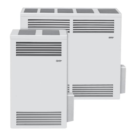
Natural Gas - CDV155DPPD, CDV255DPPD & CDV305DPPD
!
WARNING: If the information in these
instructions is not followed exactly, a fire or
explosion may result causing property damage,
personal injury or loss of life.
— Do not store or use gasoline or other flammable
vapors and liquids in the vicinity of this or any
other appliance.
— WHAT TO DO IF YOU SMELL GAS
• Do not try to light any appliance.
• Do not touch any electrical switch; do not use
any phone in your building.
• Immediately call your gas supplier from a
neighbor's phone. Follow the gas supplier's
instructions.
• If you cannot reach your gas supplier, call the
fire department.
— Installation and service must be performed by
a qualified installer, service agency or the gas
supplier.
INSTALLER: Leave this manual with the appliance.
CONSUMER: Retain this manual for future reference.
!
WARNING: This product can expose you to chemicals including epichlorohydrin
which is known to the State of California to cause cancer and birth defects and/or
other reproductive harm. For information go to www.p65warnings.ca.gov.
The appliance may be installed in an aftermarket permanently located, manufactured home (USA only) or mobile home,
where not prohibited by local codes. This appliance is only for use with the type of gas indicated on the rating plate. This
appliance is not convertible for use with other gases, unless a certified kit is used.
Cozy Heating Systems, LLC | cozyheaters.com | 888-444-1212 | 250 West Laurel Street | Colton, CA 92324
Installation and Operating Instructions
DIRECT VENT
WALL FURNACE WITH
!
alteration, service or maintenance can cause
injury or property damage. Refer to this manual
for proper installation. For assistance or for
additional information consult a qualified installer,
service agency or the gas supplier.
- The coating selected to provide longer life to
the heat exchanger may smoke slightly upon
initial firing. Provide adequate ventilation if
this occurs.
- Installation, maintenance, service,
troubleshooting & repairs must be performed
by a qualified service agency. DO NOT attempt
any of these procedures if you are not qualified
as this could expose you to property damage,
personal injury, or loss of life and will invalidate
all warranties.
- This unit is for residential use only and is not
approved for installation in greenhouses, or
environments involving dusty, wet, corrosive,
or explosive conditions. Such conditions will
invalidate the warranty and may create unsafe
conditions.
Page 1
PILOT PRO
CDV255DPPD
CDV305DPPD
CDV155DPPD
WARNING: Improper installation, adjustment,
1019068-C
Advertisement
Chapters
Table of Contents

Related Manuals for COZY CDV155DPPD


Summary of Contents for COZY CDV155DPPD
- Page 1 This appliance is only for use with the type of gas indicated on the rating plate. This appliance is not convertible for use with other gases, unless a certified kit is used. Cozy Heating Systems, LLC | cozyheaters.com | 888-444-1212 | 250 West Laurel Street | Colton, CA 92324 Page 1...
-
Page 2: Table Of Contents
CONTENTS READ CAREFULLY BEFORE INSTALLING UNIT Before Installation These installation instructions are a general guide and do not supersede applicable local codes and ordinances. Before planning Standards ........... 2 or making the installation be sure it complies with all phases of the Specifications ........ -
Page 3: Specifications
Your Direct Vent Wall Furnace is shipped complete in one carton. This carton contains the furnace, vent cap, vent tube, air inlet tube, template with rough-in dimensions, installation and operating instructions, and the thermostat with thermostat wire. NOTE: There will be two cartons if an optional vent kit or blower is purchased. MODEL NUMBERS CDV155DPPD CDV255DPPD CDV305DPPD Gas Type... -
Page 4: Venting
SAFETY - Continued It is imperative that control compartments, burner, and 20. If it is suspected that rising water may enter the furnace, circulating air passageways of the furnace be kept clean. turn off the gas immediately. Do not use this appliance if any part has been under water. -
Page 5: Clearances
CLEARANCES Inside F IX E D Corner B L E C L O S E O P E R A Detail F IX E D C L O S E = Vent Terminal = Air Supply Inlet = Area where terminal is not permitted CANADIAN REFERENCE LETTER TO DRAWING... -
Page 6: Special Precautions & Location
CLEARANCES - Continued 1. If the wall furnace is installed directly on carpeting, tile or any combustible material other than wood flooring, the wall furnace shall be installed on a metal plate or wood panel secured to the floor, extending the full width and depth of the wall furnace. 2. - Page 7 INSTALLATION WARNING: Failure to follow these instructions carefully could result in poor performance, property damage, personal injury or death. STEP 1. LOCATE VENT OPENING Locate wall studs and center 9” vent opening a minimum of 22” for CDV15 or 24-1/8” for CDV25/30 above the floor.
- Page 8 INSTALLATION FOR ALTERNATE WALL DIMENSIONS 9” TO 15" WALLS 15” TO 24” WALLS 9” TO 15” WALLS ( CDV15 / CDV25-D ) ( CDV15 / CDV25-D ) ( CDV30-D ) For 9" to 15" wall use Vent Kit No. For 15" to 24" wall use only Vent Kit For 9”...
- Page 9 INSTALLATION FIG. 4 CDV15-D CDV25/30-D 18" Cabinet 34-1/2" Cabinet 9” Dia. 9" Dia. Opening Opening 9" Valve 29-3/4" 13-3/8" 16-5/8" Inlet 31-3/4" 22" 24-1/8" Valve Inlet 8" 13” 1/2" Floor 4” Shut Off Valve 1/8” N.P.T. 1/2” Min. Center Floor Pressure Tap Line Pipe Elbow Supply...
- Page 10 INSTALLATION FIG. 7 Wall Stud Inside Wall Wall Thimble Extension Wall Thimble Assembly Vent Terminal Outside Wall Vent Terminal Spacer Plate STEP 3-B. GAS CONNECTION This heater must be connected to a gas supply capable of supplying the full rated capacity. Provide a 1/8 inch N.P.T. plugged tapping, accessible for test gauge connection, immediately upstream of the gas supply connection to the appliance.
- Page 11 Continue to page 12. Skip ahead to page 15. NOTE: Pages 12-14 are assembly NOTE: Pages 15-17 are assembly steps specifically for the CDV155DPPD steps specifically for the CDV255DPPD (this section has a gray background). and CDV305DPPD models. Page 11...
-
Page 12: Installation Steps
INSTALLATION (CDV155DPPD) STEP 5-A. Connecting the PilotPro Wires Find the three connection terminals at the base of the heater IID Valve (34). Find the green, orange and black wires that are together on one end of the Wiring Harness (57). - Page 13 INSTALLATION (CDV155DPPD) STEP 5-C. Left Side Right Side Install Install Choose which side of your heater will best accomodate the PilotPro attachment. • It can be installed on your choice of the left OR right side. • Be sure to allow room for future removal of the PilotPro cover.
- Page 14 INSTALLATION (CDV155DPPD) NOTE IF USING BLOWER KIT DVB3: Attach the wires to the Blower Shield STEP 6. Right Side Install A. Bundle and loop the wires, neatly settling them on the valve bracket. B. Allow the free ends of the wires to extend to...
- Page 15 INSTALLATION (CDV255DPPD and CDV305DPPD) STEP 5-A. Connecting the PilotPro Wires Find the three connection terminals at the base of the heater IID Valve (34). Find the green, orange and black wires that are together on one end of the Wiring Harness (57).
- Page 16 INSTALLATION (CDV255DPPD and CDV305DPPD) STEP 5-C. Left Side Install Right Side Install Choose which side of your heater will best accommodate the PilotPro attachment. • It can be installed on your choice of the left OR right side. • Be sure to allow room for future removal of the PilotPro cover. •...
- Page 17 INSTALLATION (CDV255DPPD and CDV305DPPD) STEP 6. Right Side Install 6” WARNING: Ensure wires A. Connect the orange B. Route the orange C. Allow the free ends of do not touch sparker wire and and black wires over the wires extend approx- combustion black sensor wire to to the wiring harness...
- Page 18 INSTALLATION STEP 7. Plug main Wiring Harness (57) into the Control Module (50). NOTE: Plug the wiring harness into place with the clip facing out as illustrated here. WARNING: Add the wiring sleeves on this step to prevent PilotPro damage during testing. STEP 8.
- Page 19 INSTALLATION STEP 9. A. Connect bare brown SWI wire from the control module wiring harness (57) to the white thermostat wire, using a wire nut. B. Connect the bare brown wire from the control module wiring harness (57) to the red Red Wire thermostat wire, using a (Thermostat)
- Page 20 INSTALLATION STEP 10-B. Plug the black flame sensor wire (47) into the port labeled “S” on the control module (50). Ensure it is firmly seated. NOTE: Base of the connector terminal may be slightly exposed. STEP 10-C. ENSURE THE WIRING IS DONE ACCORDING TO THIS DIAGRAM Page 20 1019068-C...
- Page 21 INSTALLATION STEP 11. TESTING Turn on all gas and electricity to the appliance. Conduct a gas leakage test of the appliance piping & control system downstream of the shutoff valve in the supply line to the appliance. Adjust thermostat to lowest setting. Place two D Batteries (62) in the Battery pack (49).
- Page 22 INSTALLATION STEP 13. TESTING Determine that the pilot is igniting and burning properly and that main burner ignition is satisfactory by turning the thermostat off and back on. Make this determination with the appliance burner both cold and hot. Perform this step as many times as is necessary to satisfy yourself that the automatic intermittent pilot system is operating properly.
- Page 23 INSTALLATION STEP 15. Check the inside of the housing for safety labels. Try to avoid drilling through any pertinent safety information during this step. Use the base of the PilotPro as a template for the following steps. Mount as directed or the wire harness will not reach.
- Page 24 INSTALLATION STEP 16. With a phillips-head screwdriver, attach the mounting plate (51) to the side of the heater cabinet (2) using: - x3 Screws #8-32 x 3/4” (55) - x3 Nuts #8 (56) USE A POWERED DRILL FOR THIS STEP, IT COULD CRACK THE MOUNTING PLATE.
- Page 25 INSTALLATION STEP 18. Re-connect the PilotPro wiring to the Control Module (50). - (33) Ignitor Wire - (47) Flame Sensor Wire - (57) IID Wiring Harness STEP 19. Ensure a protective Electrical Wire Sleeve (63) is on the red wire that extends from the Battery Pack (49).
- Page 26 INSTALLATION STEP 20. Ensure a protective Electrical Wire Sleeve (63) is on the black wire that extends from the Battery Pack (49). Connect the black wire Black Wire from the Battery Pack (49) to the black wire from the Wiring Harness (57). Black Wire Black Slide the protective...
- Page 27 INSTALLATION STEP 21. Redirect any excess length of wire between the cabinet and wall, tucking them out of sight and neatly into the heater. STEP 22. Slide the PilotPro Cover (52) in place as illustrated, and secure with the two remaining bolts (54). NOTE: Tighten in place by hand, no tools necessary.
-
Page 28: Lighting Instructions
LIGHTING INSTRUCTIONS - ( IID PILOT ) MODELS: CDV155DPPD / CDV255DPPD / CDV305DPPD Page 28 1019068-C... -
Page 29: Maintenance
MAINTENANCE WARNING: This is a gas-fired appliance. Keep the area clear of gasoline and other flammable vapors and liquids. All combustible material must be kept clear of this area to avoid fire or explosion. For proper and safe operation keep furnace and furnace If the air intake tube or the exhaust tube is removed, follow area clean. -
Page 30: Thermostat Installation
MAINTENANCE BURNER ORIFICE Fig 11: Specific Elevations This appliance is orificed at the factory for elevations up Model 0 to 2,000’ - 4,000’ - 6,000’ - 8,000’ - 2,000’ 4,000’ 6,000’ 8,000’ 10,000’ to 2,000 ft. If installed above 2,000 ft., the BTU input must be reduced 4% per 1,000 ft. -
Page 31: Installations In The State Of Massachusetts
MAINTENANCE Label all wires prior to disconnection when servicing controls. Wiring errors can cause CAUTION: improper and dangerous operation. Verify proper operation after servicing. NOTE: The furnace and all components must be inspected at least annually by a qualified service technician. This should include the burner, heat exchanger, and vent system. -
Page 32: Troubleshooting Chart
TROUBLESHOOTING CHART ( FOR QUALIFIED SERVICE TECHNICIAN ) SYMPTOM POSSIBLE CAUSES CORRECTIVE ACTION Flame 1. Defective operator section of valve. 1. Replace valve. Too Large 2. Burner orifice too large. 2. Check with local gas company for proper orifice size and replace. 3. - Page 33 KITS AND PART LIST CDV155DPPD, CDV255DPPD & CDV305DPPD Cozy Heating Systems, LLC | cozyheaters.com | 888-444-1212 | 250 West Laurel Street | Colton, CA 92324 Page 33 1019068-C...
- Page 34 DVB-3 BLOWER KIT INSTALLATION - ( OPTIONAL ) This kit must be installed by a qualified installer or service technician only. Compatable with CDV15-D / CDV25-D / CDV30-D Series. CAUTION: Label all wires prior to disconnection when servicing controls. Wiring errors can cause improper and dangerous operation.
- Page 35 DVB-3 BLOWER KIT INSTALLATION - ( OPTIONAL ) This kit must be installed by a qualified installer or service technician only. Compatable with CDV15-D / CDV25-D / CDV30-D Series. FIG. 15-A LADDER PART DESCRIPTION PART NO. SCHEMATIC BLOWER HOUSING w/ Motor & Blower 70201 JUNCTION 43610...
-
Page 36: Bbsk Installation
BBSK INSTALLATION INSTRUCTIONS - ( OPTIONAL ) This kit must be installed by a qualified installer or FIG. 16-A service technician only. 13/16" CDV15 STEP 1. Find the drilling location at the rear of the cabinet, near the top. See Figure 16-A. 3-1/4"... - Page 37 BBSK-CDV LIGHTING INSTRUCTIONS - ( OPTIONAL ) FOR YOUR SAFETY READ BEFORE LIGHTING WARNING: This appliance has a pilot which must be • If you cannot reach your gas supplier, call If you do not lighted by hand. When lighting the pilot, the fire department.
- Page 38 CDV155DPPD ) PARTS LIST - ( = 6-3/4” Dia. = 4-3/16” Dia. OPTIONAL VENT EXTENSIONS VK1525 / 9-15 Vent Kit Assembly VK1525 / 15-24 Vent Kit Assembly OPTIONAL BLOWER ASSEMBLY / DVB-3 DVB3 Blower Kit Also Includes: 43078 Cover Plate 43625 Blower Shield for CDV25/30 NOTE: Parts &...
- Page 39 CDV155DPPD ) PARTS LIST - ( ATTN: Contractors and Qualified Service Technicians: We only sell parts through our wholesalers. For prompt parts service, contact the wholesaler from which you purchased your Cozy heater. PART DESCRIPTION PART DESCRIPTION PART NO. PART NO.
- Page 40 PARTS LIST - ( CDV255DPPD et CDV305DPPD ) = 6-3/4” Dia. = 4-3/16” Dia. Ref No. 44 & 45 Not Illustrated. OPTIONAL VENT EXTENSIONS VK1525 / 9-15 & VK30 / 9-15 Vent Kit Assembly VK15/25 / 15-24 Vent Kit Assembly OPTIONAL BLOWER ASSEMBLY / DVB-3 DVB3 Blower Kit also includes:...
- Page 41 ATTN: Contractors and Qualified Service Technicians: We only sell parts through our wholesalers. For prompt parts service, contact the wholesaler from which you purchased your Cozy heater. Model Numbers ....
- Page 42 DIRECT VENT WALL FURNACE PARTS LIST : PILOT PRO CDV155DPPD, CDV255DPPD and CDV305DPPD Direct Vent IID: IID Pilot Assembly: P I L O T NOTE: Parts & schematic drawings on current models are shown at: cozyheaters.com | Specifications subject to change without notice.
- Page 43 DIRECT VENT WALL FURNACE PARTS LIST : PILOT PRO CDV155DPPD, CDV255DPPD and CDV305DPPD ATTN: Contractors and Qualified Service Technicians: We only sell parts through our wholesalers. For prompt parts service, contact the wholesaler from which you purchased your Cozy heater. PART DESCRIPTION PART NO.
- Page 44 RIGHTS AND YOU MAY ALSO HAVE OTHER RIGHTS AND ARE IN LIEU OF ALL OTHER REMEDIES. WHICH VARY FROM STATE TO STATE. TO REGISTER YOUR FURNACE: GO ONLINE TO THE COZY HEATERS WEBSITE AT: www.cozyheaters.com/warranty-registration/ COZY HEATING SYSTEMS, LLC 250 WEST LAUREL STREET – COLTON, CA 92324...
- Page 45 Cet appareil n’est pas convertible pour une utilisation avec d’autres gaz, sauf si un kit certifié est utilisé. Cozy Heating Systems, LLC | cozyheaters.com | 888-444-1212 | 250 West Laurel Street | Colton, CA 92324 Manuel en Français...
- Page 46 TABLE DES MATIÈRES LIRE ATTENTIVEMENT AVANT D’INSTALLER DE CETTE L’UNITÉ Ces directives d’installation servent de guide général et ne remplacent Avant L’installation pas les codes locaux et ordonnances applicables. S’assurer de se Normes ..........2 confonner à toutes les phases du code de chauffage local avant Spécifications ........
- Page 47 SPÉCIFICATIONS - GÉNÉRATEUR INDIVIDUEL Votre chaudière murale à prise d’air directe est expédiée en un seul carton. Ce carton contient la chaudière, le capuchon d’aération, le tuyau d’aération, le tuyau d’ admission d’ air, le modèle des dimensions des robinetteries, les instructions d’installation et de fonctionnement et le câble du thermostat.
- Page 48 SÉCURITÉ - A Continué nettoyage plus fréquent peut être requis s’ il y a un excès de 20. Si vous suspectez une montée d’eau dans la chaudière, peluche provenant de tapis, literie, etc. Il faut absolument coupez immédiatement le gaz. N’utilisez pas l’appareil si que les compartiments de commandes.
- Page 49 DÉGAGEMENTS TERMINAUX DE VENTILATION Coin F IX E Intérieur F E R M É B L E O P É R A Détail F IX É F E R M É = Borne De Passage = Admission D’Air = Secteur ou la Borne N’est Pas Autorisée INSTALLATIONS INSTALLATIONS...
- Page 50 DÉGAGEMENTS - A Continué 1. Si la chaudière est directement installée sur de la moquette, du carrelage ou tout matériau combustible autre que du plancher en bois, installez-la sur un panneau de bois ou de métal fixé au sol, de la largeur et de la profondeur de la chaudière. 2.
- Page 51 INSTALLATION ATTENTION: Si ces directives ne sont pas suivies prudemment, il pourrait y avoir comme conséquence un faible rendement, des dommages à la propriété, des blessures ou la mort. ÉTAPE 1 EMPLACEMENT DE L’OUVERTURE DU VENTILATION Déterminer l’emplacement des montants et centrer l’ouvexiure du ventilation de 22,9 mm (9 po) au moins 56 cm (22 po) au-dessus du sol pour un CDV15 et 61 cm (24-1/8 po) pour un CDV25/30.
- Page 52 INSTALLATION POUR DES DIMENSIONS DE MUR SUPPLÉMENTAIRES INSTALLATION DE LA INSTALLATION DE LA INSTALLATION DE LA FOURNAISE - MURS 22,86 CM FOURNAISE - MURS 38,10 CM À FOURNAISE- MURS 22,86 CM À À 38,10 CM (CDV15 / CDV25-D) 60,96 CM (CDV15/ CD V25-C) 38,10 CM (CDV30-D) Pour les murs de 22,86cm à...
- Page 53 INSTALLATION Schéma 4 CDV15-D CDV25/30-D 45,72 cm 87,63 cm Caisson Caisson Ouverture Ouverture dia. dia. 22,86 cm 22,86 cm Soupape 22,86 D’admission 71,76cm 33,97 42,23 de Gaz 80,65cm 55,88cm Soupape 61,28cm d’admission 20,32 de gaz 33,02cm Robinet 1.27cm Manométrique Plancer 10,16cm Robinet D’arrêt NPT .32cm...
- Page 54 INSTALLATION Schéma 7 Poteau Mural Mur Intérieur Prolongation du Manchon D’emboîtement Mural Manchon D’emboîtement Mural Mur Extérieur Plaque-Entretoise du Tuyau de Ventilation Tuyau de Ventilation Schéma 8 ALIMENTATION EN GAZ Ce radiateur ventilé doit être raccordé à une alimentation en gaz À...
-
Page 55: Cdv155
REMARQUE : Les pages 12 à 14 sont REMARQUE : Les pages 15 à 17 sont des des étapes d’assemblage spécifiques au étapes d’assemblage spécifiques aux modèles CDV155DPPD (cette section a un fond gris). CDV255DPPD et CDV305DPPD. Manuel en Français Page 11... - Page 56 INSTALLATION (CDV155DPPD) ÉTAPE 5-A. Connexion des fils du Pilot Pro Trouvez les trois bornes de connexion à la base de la valve IID de l’appareil de chauffage (34). Trouvez les fils vert, orange et noir qui se trouvent ensemble à l’une des extrémités du...
- Page 57 INSTALLATION (CDV155DPPD) ÉTAPE 5-C. Installation Installation Côté Gauche Côté Droit ≤ 25.4cm ≤ 25.4cm Choisissez le côté de votre appareil de chauffage qui s’adaptera le mieux à l’accessoire Pilot Pro. • Vous pouvez l’installer sur le côté droit ou gauche.
- Page 58 INSTALLATION (CDV155DPPD) REMARQUE SI VOUS UTILISEZ LE KIT VENTILATION DVB3 : Fixez les fils au déflecteur de ventilation ÉTAPE 6. Installation du Côté Droit A. Regroupez et bouclez les fils. Installez-les soigneusement sur le support de valve. B. Laissez les extrémités libres des fils s’étendre...
- Page 59 INSTALLATION (CDV255DPPD y CDV305DPPD) ÉTAPE 5-A. Connexion des fils du Pilot Pro Trouvez les trois bornes de connexion à la base de la valve IID de l’appareil de chauffage (34). Trouvez les fils vert, orange et noir qui se trouvent ensemble à...
- Page 60 INSTALLATION (CDV255DPPD y CDV305DPPD) ÉTAPE 5-C. Installation Côté Gauche Installation Côté Droit ≤ 25.4cm ≤ 25.4cm Choisissez le côté de votre appareil de chauffage qui s’adaptera le mieux à l’accessoire Pilot Pro. • Vous pouvez l’installer sur le côté droit ou gauche. •...
- Page 61 INSTALLATION (CDV255DPPD y CDV305DPPD) ÉTAPE 6. Installation du Côté Droit 15.2 Avertissement : Assurez-vous que les fils ne touchent A. Branchez le fil B. Acheminez C. Laissez les extrémités pas la chambre de d’allumage orange et le les fils orange libres des fils s’étendre à...
- Page 62 INSTALLATION ÉTAPE 7. Branchez le faisceau de câbles principal (57) dans le module de commande (50). REMARQUE : Branchez le faisceau de câbles en place avec le clip orienté vers l’extérieur, comme illustré ici. ATTENTION : Ajoutez gaines de câblage à cette étape-ci pour éviter d’endommager le Pilot Pro pendant l’étape d’essai. ÉTAPE 8.
- Page 63 INSTALLATION ÉTAPE 9. A. Connectez le fil SWI marron nu du faisceau de câbles du module de commande (57) au fil blanc du thermostat à l’aide d’un capuchon de connexion. B. Connectez le fil marron nu du faisceau de câbles du module de commande (57) au fil Fil Rouge rouge du thermostat à...
- Page 64 INSTALLATION ÉTAPE 10-B. Branchez le fil noir du détecteur de flamme (47) dans le port marqué « S » du module de commande (50). Assurez-vous qu’il est bien en place. REMARQUE : La base de la borne du connecteur peut être légèrement exposée.
- Page 65 INSTALLATION ÉTAPE 11. ESSAI Allumez l’alimentation en gaz et en électricité de l’appareil. Effectuez un test de fuite de gaz de la tuyauterie et du système de contrôle de l’appareil en aval de la valve d’arrêt, dans la conduite d’alimentation de l’appareil. Réglez le thermostat au réglage le plus bas.
- Page 66 INSTALLATION ÉTAPE 13. ESSAI Déterminez que le pilote s’allume et brûle correctement et que le brûleur principal s’allume correctement en éteignant puis en rallumant le thermostat. Assurez-vous que tout cela fonctionne aussi bien lorsque le brûleur de l’appareil est chaud que froid.
- Page 67 INSTALLATION ÉTAPE 15. Vérifiez l’intérieur du boîtier pour les étiquettes de sécurité. Essayez d’éviter de percer à travers les informations de sécurité au cours de cette étape. Utilisez la base de Pilot Pro comme modèle pour les étapes suivantes. Montez l’assemblage de la manière indiquée ou le faisceau de câbles n’atteindra pas la connexion.
-
Page 68: Pilot Pro (All Models)
INSTALLATION ÉTAPE 16. À l’aide d’un tournevis cruciforme, fixez la plaque de montage (51) sur le côté du boîtier de l’appareil de chauffage (2) à l’aide de: - x3 vis no 8-32 x 3/4 po (55) - x3 écrous no 8 (56) N’UTILISEZ PAS DE PERC- EUSE ÉLECTRIQUE À... - Page 69 INSTALLATION ÉTAPE 18. Rebranchez le câblage du Pilot Pro au module de commande (50). - (33) Fil d’allumage - (47) Fil du détecteur de flamme - (57) Faisceau de câbles IID ÉTAPE 19. Assurez-vous qu’une gaine de protection (63) est mise en place sur le fil rouge qui s’étend Cable du bloc de batteries (49).
- Page 70 INSTALLATION ÉTAPE 20. Assurez-vous qu’une gaine de protection (63) est installée sur le fil noir qui s’étend du bloc de batteries (49). Connectez le fil noir du bloc de Cable Noir batteries (49) et le fil noir du faisceau de câbles (57). Cable Noir Cable Glissez la gaine de protection...
- Page 71 INSTALLATION ÉTAPE 21. Redirigez toute longueur excessive de fil entre le boîtier et le mur, en dissimulant les fils et en les rangeant soigneusement près de l’appareil de chauffage. ÉTAPE 22. Glissez en place le couvercle du Pilot Pro (52) comme illustré...
- Page 72 INSTRUCTIONS POUR L’ALLUMAGE - ( IID PILOT ) MODÈLE: CDV155DPPD / CDV255DPPD / CDV305DPPD SÉCURITÉ – LIRE AVANT D’ALLUMER ATTENTION: IL FAUT SUIVRE CES INSTRUCTIONS SOIGNEUSEMENT POUR ÉVITER UN INCENDIE OU UNE EXPLOSION QUI PEUT CAUSER DES DÉGÂTS, DES BLESSURES OU LA MORT.
- Page 73 ENTRETIEN MISE EN GARDE: Cet appareil fonctionne au gas. Ne pas entreposer ou utiliser de l’essence ou d’autres liquides ou vapeurs inflammables aux alentours de cet appareil. Toute matière combustible doit être gardée loin de cet appareil de chauffage afin d’éviter une incendie ou une explosion. Garder la foumaise et l‘aire de la fournaise propres pour un Ne pas obstruer l’air de combustion et de ventilation.
- Page 74 ENTRETIEN ORIFICE DU BRÛLEUR Schéma 11: Altitudes Spécifiques La grosseur le l’orifice de cet appareil a été déterminée en Numéros 609.61 a 1219.21 a 1828.82 a 2438.43 a de Modéle 609.61m 1219.21 m 1828.82 m 2438.43 m 3048.04 m usine pour des altitudes jusqu’à 609,61 m. Si cet appareil est installé...
- Page 75 ENTRETIEN ATTENTION: Au moment de l’entretien des commandes étiquetez tous les fils avant le débranchement. Des erreurs de câblage peuvent entraîner un fonctionnement inadéquat et dangereux. REMARQUE - La fournaise et tous ses composants doivent être inspectés au moins annuellement par un technicien d’entretien qualifié.
- Page 76 TABLEAU DE DÉPANNAGE ( A utiliser par un installateur ou un technicien d’entretien qualifié. ) PROBLÈME CAUSE POSSIBLE ACTION CORRECTIVE FLAMME 1. Soupape defective. 1. Remplacer la soupape. TROP 2. Orifice trop grand du brûleur. 2. Vérifier avec la société gazière locale pour la taille appropriée d’orifice et remplacer. GRANDE 3.
- Page 77 KITS AND PART LIST CDV155DPPD, CDV255DPPD & CDV305DPPD Cozy Heating Systems, LLC | cozyheaters.com | 888-444-1212 | 250 West Laurel Street | Colton, CA 92324 Manuel en Français Page 33 1019074-C...
- Page 78 KIT SOUFFLEUR DVB-3 NOTICE D’INSTALLATION - ( FACULTATIF ) Ce kit doit être installé uniquement par un installateur qualifié ou un technicien de maintenance. Compatible avec les séries CDV15-D / CDV25-D / CDV30-D. ATTENTION: Au moment de l’entretien des commandes étiquetez tous les fils avant le débranchement. Des erreurs de câblage peuvent entraîner un fonctionnement inadéquat et dangereux.
- Page 79 KIT SOUFFLEUR DVB-3 NOTICE D’INSTALLATION - ( FACULTATIF ) Ce kit doit être installé uniquement par un installateur qualifié ou un technicien de maintenance. Compatible avec les séries CDV15-D / CDV25-D / CDV30-D. Schéma 15-A SCHÉMA DESCRIPTION DE PIÈCE PIÈCE DÉCHELLE BOITER DE VENTILATEUR av/ moteur et souffleur 70201...
- Page 80 INSTRUCTIONS D’INSTALLATION DU KIT BBSK - ( FACULTATIF ) Ce kit doit être installé uniquement par un installateur qualifié ou Schéma 16-A un technicien de maintenance. 2,06375cm CDV15 ÉTAPE 1. Trouvez l’emplacement de forage à l’arrière de l’armoire, près du sommet. Voir Schéma 16-A. 8,255cm ÉTAPE 2.
- Page 81 INSTRUCTIONS D’ALLUMAGE DU MODÈLE BBSK - ( FACULTATIF ) PAR SOUCI DE SÉCURITÉ, LIRE AVANT D’ALLUMER MISE Cet appareil est équipé d’une veilleuse qui doit être instructions du fournisseur de gaz. EN GARDE: allumée manuellement. Il faut suivre scrupuleusement • S’il n’est pas possible d’atteindre le fournisseur Si vous ne ces consignes lors de l‘allumage de la veilleuse.
- Page 82 LISTE DES PIÈCES - ( CDV155DPPD ) = 17.145 cm Dia. = 10.6299 cm Dia. EXTENSIONS D’ÉVENT EN OPTION VK1525 / 9-15 Ensemble de kit ventilation VK1525 / 15-24 Ensemble de kit ventilation ENSEMBLE OPTIONNEL DE VENTILATEUR / DVB-3 Le Kit DVB3 Comprend Également :...
- Page 83 LISTE DES PIÈCES - ( CDV155DPPD ) ATTENTION : Entrepreneurs et techniciens de service qualifiés : Nous vendons uniquement des pièces par l’intermédiaire de nos grossistes. Pour de l’assistance rapide avec les pièces, contactez le grossiste auprès duquel vous avez acheté votre appareil de chauffage Cosy.
- Page 84 LISTE DES PIÈCES - ( CDV255DPPD et CDV305DPPD ) = 6-3/4” Dia. = 4-3/16” Dia. Réf No. 44 & 45 Non Illustré EXTENSIONS D’ÉVENT EN OPTION VK1525 / 9-15 et VK30 / 9-15 Ensemble de kit ventilation VK15/25 / 15-24 Ensemble de kit ventilation ENSEMBLE OPTIONNEL DE VENTILATEUR / DVB-3 Le kit de soufflerie...
- Page 85 ATTN: Entrepreneurs et techniciens de service qualifiés: Nous ne vendons des pièces que par l’intermédiaire de nos grossistes. Pour un service de pièces rapide, contactez le grossiste chez qui vous avez acheté votre appareil de chauffage Cozy. Pièces des Modèles ... . .
- Page 86 LISTE DES PIÈCES : PILOTE PRO POUR CHAUFFAGE MURAL POUR VENTILA DIRECTA ( CDV155DPPD, CDV255DPPD et CDV305DPPD ) Ventilation Directe du Pilote IID: Assemblé du Pilote IID: P I L O T E REMARQUE: Les pièces et les schémas des modèles actuels sont affichés sur: cozyheaters.com | Spécifications sujettes à changement sans préavis.
- Page 87 ( CDV155DPPD, CDV255DPPD et CDV305DPPD ) ATTN: Entrepreneurs et techniciens de service qualifiés: Nous ne vendons des pièces que par l’intermédiaire de nos grossistes. Pour un service de pièces rapide, contactez le grossiste chez qui vous avez acheté votre appareil de chauffage Cozy. RÉF. # LISTE DES PIÈCES DU PILOT PRO...
- Page 88 PEUT ETRE D’AUTRES DROITS VARIANT SELON RECOURS POSSIBLE POUR L’UTILISATEUR VOTRE PAYS POUR ENREGISTRER VOTRE FOURNAISE : Allez en ligne sur le site Web de Cozy Heaters à l’adresse : www.cozyheaters.com/warranty-registration/ COZY HEATING SYSTEMS, LLC 250 WEST LAUREL STREET – COLTON, CA 92324 Manuel en Français...
- Page 89 No es posible hacerlo funcionar con ningún otro tipo de gas, a menos que se use un kit (juego) certificado. Cozy Heating Systems, LLC | cozyheaters.com | 888-444-1212 | 250 West Laurel Street | Colton, CA 92324 Manual en Español...
- Page 90 TABLA DE CONTENIDO LEA ESTA SECCIÓN ANTES DE INSTALAR LA UNIDAD Antes de la instalación Este instructivo es una guía general para su aparato y no substituye los códigos y reglamentos locales que aplican. Antes de planear o Normas ..........2 realizar la instalación, asegúrese de que cumple con todas las fases Especificaciones .........
-
Page 91: Introducción
NOTA: Si se compra el kit o soplador de ventilación opcjonal habrá dos cartones. NÚMEROS DE MODELOS CDV155DPPD CDV255DPPD CDV305DPPD Tipo de Gas... -
Page 92: Ventilation
REGLAS DE SEGURIDAD - Continuado técnico de servicio calificado. Quizá sea necesario limpiar 20. Si se sospecha que el nivel de agua puede liegar a penetrar con más frecuencia el aparato debido a un exceso de pelusa el horno, cierre el gas inmedíatamente. No use este aparato de las alfombras, blancos, etc. -
Page 93: Espacios Libres
ESPACIOS LIBRES Detalle de F IJ O la Esquina B L E O P E R A C E R R A F IJ O Interior C E R R A = Terminal de Ventilación = Entrada de Suministro de Aire = Área Donde no se Permite el Terminal Instalaciones... -
Page 94: Precauciones Especiales
ESPACIOS LIBRES - Continuado 1. Si la calefacción de pared está instalada directamente sobre la alfombra, azulejo u otro material que no sea piso de madera, la calefacción de pared debe ser instalada sobre una placa de metal o panel de madera asegurado al suelo, extendiendo todo el ancho y profundidad de la calefacción de pared. - Page 95 INSTALACIÓN PRECAUCIÓN: El incumplimiento de estas instrucciones con cuidado puede provocar un rendimiento deficiente, daños a la propiedad, lesiones personales o la muerte. PASO 1. UBICACIÓN DE APERTURA PARA LA VENTILA. Ubique los pernos de la pared y centre la abertura de ventilación de 9”, como mínimo, 22” para CDV15 o 24-1/8” para CDV25/30 sobre el piso.
- Page 96 INSTALACIÓN PARA DIMENSIONES DE PARED ADICIONALES INSTALACIÓN DEL CALEFACTOR INSTALACIÓN DEL CALEFACTOR INSTALACIÓN DEL PAREDES DE 22.86 CM A 38.10 CM PAREDES DE 38.10 CM A 60.96 CM CALEFACTOR PAREDES DE ( CDV15 / CDV25-D ) (CDV15 / CDV25-D) 22.86 CM A 38.10 CM (CDV30-D) Para paredes de 22.86 cm a 38.10 cm, utilice El VK1525/15-24-B se utiliza con los modelos Para paredes de 22.86 cm a 38.10 cm, utilice el...
- Page 97 INSTALACIÓN Illustración 4 CDV15-D CDV25/30-D 45.72 cm 87.63 cm Gabinete Gabinete Apertura Apertura del diametro del diametro 22.86 cm 22.86 cm Entrada 22.86 de Valvula 71.76cm 33.97 42.23 de Gas 80.65cm 55.88cm Entrada 61.28cm de Valvula 20.32 de Gas 33.02cm Llave de 1.27cm Presión de...
- Page 98 INSTALACIÓN Illustración 7 Entramado de la Pared Pared Interior Extension del Guardacabo de la Pared Calefactor Ensamble del Guardacabo de la Pared Pared Exterior Placa Espaciadora para la Terminal de la Ventila Terminal de Ventila Illustración 8 PASO 3-B. CONEXIÓN DEL GAS Este calentador debe estar conectado a un suministro de gas A la Válvula de Control de Gas capaz de suministrar la capacidad nominal completa.
- Page 99 Continúe en la página 12. Pase a la página 15. NOTA: Las páginas 12-14 son pasos de NOTA: Las páginas 15-17 son pasos montajes específicos para el CDV155DPPD de montaje específicos para los modelos (esta sección tiene un fondo gris). CDV255DPPD y CDV305DPPD.
- Page 100 INSTALACIÓN (CDV155DPPD) PASO 5-A. Conexión de los Cables Pro Piloto Encuentre los tres terminales de conexión en la base de la válvula IID del calentador (34). Encuentre los cables verde, naranja y negro que están juntos en un extremo del mazo de cables (57).
- Page 101 INSTALACIÓN (CDV155DPPD) PASO 5-C. instalación instalación del lado del lado izquierdo derecho ≤ 25.4cm ≤ 25.4cm Elija qué lado de su calentador adaptará mejor el accesorio Pro piloto. • Se puede instalar del lado izquierdo O derecho, según la opción elegida.
- Page 102 INSTALACIÓN (CDV155DPPD) NOTA SI USA EL KIT DE VENTILADOR DVB3: Conecte los cables al protector delventilador PASO 6. Instalación del Lado Derecho A. Ate y enrolle los cables, colocándolos de forma cuidadosa en el soporte de la válvula. B. Permita que los...
- Page 103 INSTALACIÓN (CDV255DPPD y CDV305DPPD) PASO 5-A. Conexión de los Cables Pro Piloto Encuentre los tres terminales de conexión en la base de la válvula IID del calentador (34). Encuentre los cables verde, naranja y negro que están juntos en un extremo del mazo de cables (57).
- Page 104 INSTALACIÓN (CDV255DPPD y CDV305DPPD) PASO 5-C. instalación del lado instalación izquierdo del lado derecho ≤ 25.4cm ≤ 25.4cm Elija qué lado de su calentador adaptará mejor el accesorio Pro piloto. • Se puede instalar izquierdo O derecho, según la opción elegida. •...
- Page 105 INSTALACIÓN (CDV255DPPD y CDV305DPPD) PASO 6. Instalación del Lado Derecho 15.2 ADVERTENCIA: Asegúrese de que los cables A. Conecte el cable naranja C. Permita que los extremos B. Dirija los no toquen la de encendido y el cable cables naranja libres de los cables se extien- cámara de negro del sensor a la...
- Page 106 INSTALACIÓN PASO 7. Conecte el arnés de cableado principal (57) en el módulo de control (50). NOTA: Enchufe el arnés de cableado en su lugar con el clip hacia afuera como se muestra aquí. ADVERTENCIA: Agregue los manguitos cableado en este paso para evitar daños al Pro piloto durante la prueba. PASO 8.
- Page 107 INSTALACIÓN PASO 9. A. Conecte el cable SWI marrón desnudo del mazo de cables del módulo de control (57) al cable blanco del termostato, utilizando una tuerca para cable. B. Conecte el cable marrón desnudo del Cable Rojo mazo de cables del (Termostato) módulo de control (57) al cable rojo del termostato,...
- Page 108 INSTALACIÓN PASO 10-B. Enchufe el cable negro del sensor de llama (47) en el puerto con la etiqueta “S” en el módulo de control (50). Asegúrese de que esté asentado con firmeza. Nota: La base del terminal conector puede estar levemente expuesta.
- Page 109 INSTALACIÓN PASO 11. PRUEBAS Encienda todo el gas y la electricidad al aparato. Realice una prueba de fuga de gas de la tubería del aparato y el sistema de control aguas abajo de la válvula de cierre en la línea de suministro al aparato. Ajuste el termostato a la configuración más baja.
- Page 110 INSTALACIÓN PASO 13. TESTING Determine que el piloto se está encendiendo y quemando de forma correcta y que el encendido del quemador principal sea satisfactorio apagando y volviendo a encender el termostato. Haga esta determinación con el quemador del aparato tanto frío como caliente. Realice este paso tantas veces como sea necesario para asegurarse de que el sistema piloto intermitente automático funcione correctamente.
- Page 111 INSTALACIÓN PASO 15. Check the inside of the housing for safety labels. Try to avoid drilling through any pertinent safety information during this PASO. Use la base de Pro piloto como plantilla para los siguientes PASOs. Monte como se indica o el mazo de cables no llegará.
- Page 112 INSTALACIÓN PASO 16. Con un destornillador Phillips, fije la placa de montaje (51) al costado del gabinete del calentador (2) usando: - x3 Tornillos # 8-32 x 3/4” (55) - x3 Tuercas # 8 (56) NO UTILICE UN TALADRO ELÉCTRICO PARA ESTE PASO PODRÍA ROMPER LA PLACA DE MONTAJE.
- Page 113 INSTALACIÓN PASO 18. Vuelva a conectar el cableado del Pro piloto al Módulo de control (50). - (33) Cable del dispositivo de encendido - (47) Cable del sensor de llama - (57) Mazo de cables IID PASO 19. Garantiza una protección manguito del cable eléctrico (63) está...
- Page 114 INSTALACIÓN PASO 20. Asegúrese de que haya una manga protectora de cable eléctrico (63) en el cable negro que se extiende desde la batería (49). Cable Conecte el cable negro del Negro Paquete de Baterías (49) al cable negro del mazo de cables (57).
- Page 115 INSTALACIÓN PASO 21. Redireccione cualquier exceso de cable entre el gabinete y la pared, ocultándolos y colocándolos de forma cuidadosa en el calentador. PASO 22. Deslice la Cubierta Pro piloto (52) en su lugar como se ilustra, y asegúrela con los dos pernos restantes (54).
-
Page 116: Instrucciones De Encendido
INSTRUCCIONES DE ENCENDIDO - ( PILOTO IID ) MODELOS: CDV155DPPD / CDV255DPPD / CDV305DPPD Manual en Español Page 28 1019073-D... -
Page 117: Mantenimiento
MANTENIMIENTO ADVERTENCIA: Este aparato funciona a gas. Mantenga el área libre de gasolina y de otros vapores y líquidos inflamables. Todo material combustible se debe mantener alejado de esta área para evitar que haya incendios o explosion. Para que su calefactor tenga un funcionamiento apropiado y revisión anual de seguridad del funcionamiento de su aparato. -
Page 118: Instalación Del Termostato
MANTENIMIENTO ESPREAS DEL QUEMADOR Illustración 11: ELEVACIÓN ESPECÍFICA Este aparato viene con las espreas del quemador de fábrica Números 609.61 a 1219.21 a 1828.82 a 2438.43 a de Model 609.61m 1219.21 m 1828.82 m 2438.43 m 3048.04 m para elevaciones de hasta 609.61 metros. Si se instala por encima de una elevación de 609.61 metros, la entrada GAS NATURAL del BTU se debe reducir 4% por 304.80 metros. -
Page 119: Instalaciones En El Estado De Massachusetts
MANTENIMIENTO Etiquete todos los cables antes de la desconexión al realizar el mantenimiento de PRECAUCIÓN: los controles. Los errores de cableado pueden causar un funcionamiento incorrecto y peligroso. Verificar el funcionamiento correcto después del servicio. NOTA: El calefactor y todos los componentes se deben inspeccionar por lo menos usa vez al año por un técnico de servicio calificado. -
Page 120: Tabla De Localización Problemas
TABLA DE LOCALIZACIÓN DE PROBLEMAS ( Para ser usado por un instalador o un técnico de servicio calificados. ) SÍNTOMA CAUSAS POSIBLES ACCÍON CORRECTIVA LA LLAMA ESTÁ 1. Sección defectuosa de la válvula. 1. Cambie la válvula. MUY GRANDE 2. Esprea del quemador demasiado grande. 2. - Page 121 KITS Y LISTA DE PIEZAS CDV155DPPD, CDV255DPPD y CDV305DPPD Cozy Heating Systems, LLC | cozyheaters.com | 888-444-1212 | 250 West Laurel Street | Colton, CA 92324 Manual en Español Page 33 1019073-D...
- Page 122 INSTRUCCIONES DE INSTALACION PARA EL KIT DEL SPOLADOR DVB-3 - ( OPCIONAL ) Este kit solo debe instalarlo un instalador calificado o un técnico de servicio. Compatible con la serie CDV15-D / CDV25-D / CDV30-D. PRECAUCIÓN: Etiquete todos los cables antes de la desconexión al realizar el mantenimiento de los controles.
- Page 123 INSTRUCCIONES DE INSTALACION PARA EL KIT DEL SPOLADOR DVB-3 - ( OPCIONAL ) Este kit solo debe instalarlo un instalador calificado o un técnico de servicio. Compatible con la serie CDV15-D / CDV25-D / CDV30-D. Illustración 15-A ESQUEMA DESCRIPCIÓN DE LA PARTE NÚM.
- Page 124 INSTRUCCIONES PARA LA INSTALACIÓN DEL KIT BBSK - ( OPCIONAL ) Este kit solo debe instalarlo un instalador calificado o un Illustración 16-A técnico de servicio. 2,06375cm CDV15 PASO 1. Encuentre la ubicación de perforación en la parte posterior del gabinete, cerca de la parte superior.
- Page 125 INSTRUCCIONES DE ENCENDIDO PARA EL MODELO BBSK - ( OPCIONALES ) PARA SU SEGURIDAD LEA ESTE INSTRUCTIVO ANTES DE ENCENDER EL APARATO ADVERTENCIA: SI NO Este aparato tiene un piloto que se debe encender • Si no puede comunicarse con la compañía de gas, SIGUE ESTAS a mano.
-
Page 126: Lista De Piezas
LISTA DE PIEZAS - ( CDV155DPPD ) = 17.145 cm Dia. = 10.6299 cm Dia. EXTENSIONES OPCIONALES DEL RESPIRADERO VK1525 / 9-15 Juego para el Ensamble de la Ventila VK1525 / 15-24 Juego para el Ensamble de la Ventila MONTAJE DEL VENTILADOR OPCIONAL / DVB-3 DVB-3 Ventilador Kit También Incluye:... - Page 127 LISTA DE PIEZAS - ( CDV155DPPD ) ATENCIÓN: Contratistas y técnicos de servicio calificados: Solo vendemos piezas a través de nuestros mayoristas. Para un servicio rápido de piezas, comuníquese con el mayorista al que compró su calentador Cozy. PART DESCRIPTION PART DESCRIPTION PART NO.
- Page 128 LISTA DE PIEZAS - ( CDV255DPPD y CDV305DPPD ) = 17.145 cm Dia. = 10.6299 cm Dia. # Réf. 44 y 45 No ilustrado EXTENSIONES OPCIONALES DEL RESPIRADERO VK15 / 25-9-15 y VK30/9-15 Juego para el Ensamble de la Ventila VK15 / 25-15-24 Juego para el Ensamble Ventila VENTILATEUR FACULTATIF / DVB-3...
- Page 129 ATENCIÓN: Contratistas y técnicos de servicio calificados: Solo vendemos piezas a través de nuestros mayoristas. Para un servicio rápido de piezas, comuníquese con el mayorista al que compró su calentador Cozy. Números de Modelo ... . .
- Page 130 LISTA DE PIEZAS : PILOTO PRO PARA EL CALEFACTOR DE PARED DE VENTILA DIRECTA ( CDV155DPPD, CDV255DPPD y CDV305DPPD ) Ventila Directa: IID Piloto Assemblea: P I L O T O NOTA: Las partes y los esquemas del modelo actual se publican en: cozyheaters.com | Las especificaciones están sujetas a cambios sin previo aviso.
- Page 131 ( CDV155DPPD, CDV255DPPD y CDV305DPPD ) ATENCIÓN: Contratistas y técnicos de servicio calificados: Solo vendemos piezas a través de nuestros mayoristas. Para un servicio rápido de piezas, comuníquese con el mayorista al que compró su calentador Cozy. # RÉF. NÚMEROS DE MODEL...
-
Page 132: Garantía
VARIAR DE UN ESTADO A OTRO. duración de una garantía implícita, y algunos estados no permiten la exclusión o limitación de PARA REGISTRAR SU CALEFACTOR: Vaya en línea al sitio web de Cozy Heaters en: www.cozyheaters.com/warranty-registration/ COZY HEATING SYSTEMS, LLC 250 WEST LAUREL STREET –...
Need help?
Do you have a question about the CDV155DPPD and is the answer not in the manual?
Questions and answers