COZY CF553D-H Installation And Operating Instructions Manual
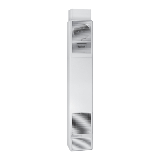
Counterflow wall furnace
Hide thumbs
Also See for CF553D-H:
- Installation and operating instructions manual (26 pages) ,
- Installation and operating instructions manual (85 pages)
Table of Contents
Advertisement
Quick Links
NATURAL GAS - CF403D - H, CF553D - H, CF407D-H, CF557D-H
PROPANE GAS - CF404D-H, CF554D-H, CF408D-H, CF558D-H
!
WARNING: If the information in these instructions
is not followed exactly, a fire or explosion may result
causing property damage, personal injury or loss of life.
— Do not store or use gasoline or other flammable vapors and
liquids in the vicinity of this or any other appliance.
— WHAT TO DO IF YOU SMELL GAS
• Do not try to light any appliance.
• Do not touch any electrical switch; do not use any phone
in your building.
• Immediately call your gas supplier from a neighbor's
phone. Follow the gas supplier's instructions.
• If you cannot reach your gas supplier, call the fire
department.
— Installation and service must be performed by a qualified
installer, service agency or the gas supplier.
INSTALLER: Leave this manual with the appliance.
CONSUMER: Retain this manual for future reference.
WARNING: This product can expose you to chemicals including epichlorohydrin
!
which is known to the State of California to cause cancer and birth defects and/or
other reproductive harm. For information go to www.p65warnings.ca.gov.
- The coating selected to provide longer life to the heat exchanger may smoke slightly upon initial firing. Please provide adequate
ventilation if this occurs.
- Installation, maintenance, service, troubleshooting & repairs must be performed by a qualified service agency. DO NOT attempt any of
these procedures if you are not qualified as this could expose you to property damage, personal injury, or loss of life and will invalidate
all warranties.
- This unit is for residential use only and is not approved for installation in greenhouses, or environments involving dusty, wet, corrosive,
or explosive conditions. Such conditions will invalidate the warranty and may create unsafe conditions.
- This appliance is equipped with a blocked flue switch designed to protect against improper venting of combustion products.
- THIS UNIT IS NOT TO BE INSTALLED IN MOBILE HOMES.
WARNING: Operation of this furnace without the properly installed, furnished vent system and vent cap could result in Carbon
Monoxide (CO) poisoning and possible death. For your safety, this furnace and the vent system should be inspected at least
annually by a qualified service technician.
Cozy Heating Systems | cozyheaters.com | 888-444-1212 | 250 West Laurel Street | Colton, CA 92324
Installation and Operating Instructions
COUNTERFLOW
WALL FURNACE
!
alteration, service or maintenance can cause
injury or property damage. Refer to this manual
for proper installation. For assistance or for
additional information consult a qualified installer,
service agency or the gas supplier.
Page 1
CF40
WARNING: Improper installation, adjustment,
CF55
1018029-E_03/22
Advertisement
Table of Contents

Subscribe to Our Youtube Channel
Related Manuals for COZY CF553D-H


Summary of Contents for COZY CF553D-H
- Page 1 Monoxide (CO) poisoning and possible death. For your safety, this furnace and the vent system should be inspected at least annually by a qualified service technician. Cozy Heating Systems | cozyheaters.com | 888-444-1212 | 250 West Laurel Street | Colton, CA 92324 Page 1...
-
Page 2: Table Of Contents
CONTENTS READ CAREFULLY BEFORE INSTALLING UNIT Before Installation These installation instructions are a general guide and do not supersede applicable local codes and ordinances. Before planning Standards ........... 2 or making the installation be sure it complies with all phases of the Specifications ........ -
Page 3: Specifications
While the burner access door is open, check the rating plate to verify that the model number is correct and that the wall furnace is equipped for the type gas you intend to use. CF403D-H CF407D-H CF553D-H CF557D-H CF404D-H CF408D-H... -
Page 4: Venting
VENTING This appliance must be properly connected to a venting system. Consult local ordinances governing venting. Install only UL listed type BW 4” oval gas vent. When the vent enters the attic, a listed type B-1 round flue pipe may be used. See Figure 1, Page 5. Vent pipe must connect to the wall furnace or header plate with a “B”... - Page 5 VENTING WARNING: Do not bypass the blocked flue switch. To do so could expose the consumer to property damage, personal injury or possible death. FIG. 1 FIG. 2: Vent Installation More than 10’ Height above any roof surface 10’ within 10’ horizontally Listed Vent Top...
-
Page 6: Combustion & Ventilation
COMBUSTION AND VENTILATION AIR When installed, this gas appliance must be provided with fresh air for combustion, ventilation, and dilution of hot flue gases. The minimum required volume of the area where the appliance is installed should be 50 cubic feet per 1,000 BTU/HR. If installed in an area of the home that is considered an unconfined space, the natural infiltration of air around windows and doors will be adequate. -
Page 7: Locations
COMBUSTION AND VENTILATION AIR FIG. 4-A FIG. 4-B UL Listed Vent Cap UL Listed Vent Cap UL Listed Gas Vent UL Listed Gas Vent Ventilation Louvers (each end of attic) Opening Outlet Air Inlet Air Opening Ventilation Louvers for Unheated Crawl Space ALL COMBUSTION AIR FROM ALL COMBUSTION AIR FROM OUTDOORS. -
Page 8: Rough-In Instructions
LOCATION AND SPECIAL PRECAUTIONS FIG. 5 Using Adjacent Stud Space for All Combustion Air From Outside The wall furnace should be located near the center of the area to be heated for optimal heat distribution. If the wall furnace is installed directly on carpeting, tile or Holes Connecting to Ventilated Attic any combustible material other than wood flooring, the wall furnace shall be installed on a metal plate or wood panel... - Page 9 ELECTRICAL ROUGH-IN FIG. 7 115 V.A.C. Line In Rough in 115 v. wiring, terminating inside the junction box located on top of header plate for recessed, or in a receptacle box (not provided) for flush mount. Vent Pipe Consult local codes or ordinances. See Figure 7. Stud MODEL NUMBER AMPS...
-
Page 10: Installing
INSTALLATION NOTE: For proper combustion, make sure units are level front to back and side to side. RECESSED UP TO 9-1/4” INSTALLATION FIG. 10 Cut out floor plate between 2x4 studs, so heater will set flat on floor. Make electrical connection of 115 V. wiring into junction box provided on top of header plate. -
Page 11: Controls
INSTALLATION FIG. 12 FIG. 13 Ceiling plate spacers Firestop spacers supplied by to center B-W gas vent manufacturer of B-W gas vent. Installation of in stud space - nail Installation of B-W gas vent B-W Gas Vent securely at both ends. for each subsequent ceiling or for one story floor level of multi-story... -
Page 12: Lighting Instructions
LIGHTING INSTRUCTIONS - ( Standing Pilot ) MODELS: CF403D-H / CF404D-H / CF553D-H / CF554D-H FOR YOUR SAFETY READ BEFORE LIGHTING WARNING: This appliance has a pilot which must be • If you cannot reach your gas supplier, call If you do not lighted by hand. - Page 13 LIGHTING INSTRUCTIONS - ( IID Pilot ) MODELS: CF407D-H / CF408D-H / CF557D-H / CF558D-H FOR YOUR SAFETY READ BEFORE LIGHTING WARNING: This appliance is equipped with an ignition • If you cannot reach your gas supplier, call If you do not device which automatically lights the pilot.
-
Page 14: Proper Burner Flame
PROPER BURNER FLAME OPERATION A proper flame will have a dark blue inner mantle that sits This heater is equipped with a slow opening gas control. right on top of the burners with a lighter blue outer mantle On a call for heat the gas valve does not snap-open to full rising above the burner, (See Figure 15). -
Page 15: Terminal Block Wiring Diagram
TERMINAL BLOCK WIRING DIAGRAM MAINTENANCE INSTRUCTIONS Installation and repair must be done by a qualified service technician. The appliance should be inspected before use CAUTION: and at least annually by a professional service technician. Label all wires prior to disconnection when More frequent cleaning may be required due to excessive servicing controls. -
Page 16: Wiring Schematics
WIRING SCHEMATICS Standing Pilot Models IID Models 1. Spark 2. Sense 3. 24V 4. 24V 5. Gnd. 6. Gnd. (Burner) 7. PV 8. MV/PV 9. MV 1018029-E Page 16... -
Page 17: 14-Pek Extension Kit
14-PEK: 14’ PLUG EXTENSION KIT (For NON-Recessed Installations Only) CAUTION: These kits must be installed by a qualified installer or service technician. FIG. 16 Units with Terminal Board Turn heater off following Section 3 in the Lighting Instructions and allow to cool. 90 DEGREE OUTSIDE Turn off all electricity to heater. -
Page 18: 406Rr-A Rear Register Kit
KITS (Optional Accessories) CAUTION: These kits must be installed by a qualified installer or service technician. 406RR-A 407RR-A REAR REGISTER KIT ( Flush Mount ) REAR DISCHARGE KIT ( Recessed ) FIG. 17-A FIG. 18-A Plaster Ground 1/2” Plaster Ground 14-3/8”... -
Page 19: 306Sr-A And 30Srb-A: Side Discharge Kits
KITS (Optional Accessories) CAUTION: These kits must be installed by a qualified installer or service technician. 306SR-A 30SRB-A SIDE DISCHARGE ON CASING ( Flush Mount ) SIDE DISCHARGE ( With Extension Boot ) FIG. 19 FIG. 20 18” Min. Cut out and remove embossed area on casing side. Cut opening in drywall as shown in Fig. -
Page 20: Troubleshooting Charts
TROUBLESHOOTING CHART ( FOR QUALIFIED SERVICE TECHNICIAN ) - MAIN BURNER Please follow the following corrective actions in order. SYMPTOM POSSIBLE CAUSES CORRECTIVE ACTION Flame Too 1. Defective operator section of gas 1. Replace complete valve. Large valve. 2. Burner orifice too large. 2. -
Page 21: Installations In The State Of Massachusetts
TROUBLESHOOTING CHART ( FOR QUALIFIED SERVICE TECHNICIAN ) - PILOT AND VALVE Please follow the following corrective actions in order. SYMPTOM POSSIBLE CAUSES CORRECTIVE ACTION Burner Won’t 1. Gas valve not turned on. 1. Turn gas valve to “on” position”. Turn On 2. - Page 22 TROUBLESHOOTING CHART ( SPECIFICALLY FOR INTERMITTENT IGNITION SYSTEM ) - IID Please follow the following corrective actions in order. GREEN LED FLASH INDICATES NEXT SYSTEM ACTION RECOMMENDED SERVICE ACTION CODE (XXY)ª No Call for Heat Not Applicable None Not Applicable None Flash Fast Startup - Flame...
- Page 23 TROUBLESHOOTING CHART ( FOR QUALIFIED SERVICE TECHNICIAN ) BLOCKED FLUE SWITCH PROBLEMS The following is a list of possible causes and corrective actions for blocked flue switch problems. WARNING: Do not bypass the blocked flue switch. To do so could expose the consumer to property damage, personal injury or possible death.
-
Page 24: Cf Part List
COUNTERFLOW WALL FURNACE PARTS LIST Natural Gas: CF403D-H, CF553D-H, CF407D-H, CF557D-H Propane Gas: CF404D-H, CF554D-H, CF408D-H, CF558D-H C F 4 C F 5 HOW TO PROPERLY ORDER PARTS: ATTN: CONTRACTORS AND In addition to the part description and numbers, QUALIFIED SERVICE... - Page 25 COUNTERFLOW WALL FURNACE PARTS LIST Natural Gas: CF403D-H, CF553D-H, CF407D-H, CF557D-H Propane Gas: CF404D-H, CF554D-H, CF408D-H, CF558D-H STANDING PILOT MODELS IID PILOT MODELS CF404 CF554 CF408 CF558 Natural Gas Model Numbers ......
- Page 26 COUNTERFLOW WALL FURNACE PARTS LIST Natural Gas: CF403D-H, CF553D-H, CF407D-H, CF557D-H Propane Gas: CF404D-H, CF554D-H, CF408D-H, CF558D-H CONTROL ASSEMBLY THERMOSTAT - (Standing Pilots) Used on the CF403D-H, CF404D-H, CF553D-H and CF554D-H series. I.I.D. CONTROL MODULE CONTROL ASSEMBLY - (IID Pilots)
- Page 27 COUNTERFLOW WALL FURNACE PARTS LIST Natural Gas: CF403D-H, CF553D-H, CF407D-H, CF557D-H Propane Gas: CF404D-H, CF554D-H, CF408D-H, CF558D-H STANDING PILOT MODELS IID PILOT MODELS CF404 CF554 CF408 CF558 Natural Gas Model Numbers ......
-
Page 28: Warranty
RIGHTS AND YOU MAY ALSO HAVE OTHER RIGHTS AND ARE IN LIEU OF ALL OTHER REMEDIES. WHICH VARY FROM STATE TO STATE. TO REGISTER YOUR FURNACE: GO ONLINE TO THE COZY HEATERS WEBSITE AT: www.cozyheaters.com/warranty-registration/ COZY HEATING SYSTEMS 250 WEST LAUREL STREET – COLTON, CA 92324...
Need help?
Do you have a question about the CF553D-H and is the answer not in the manual?
Questions and answers