COZY CDV335C Installation And Operating Instructions Manual
Direct vent wall furnace
Hide thumbs
Also See for CDV335C:
- Installation and operating instructions manual (23 pages) ,
- Installation and operating instructions manual (24 pages)
Table of Contents
Advertisement
Available languages
Available languages
ENGLISH
Click here for the full manual or
click on the links below to quickly
locate what you're looking for:
Before Installation
Standards ............................................ 2
Specifications ...................................... 3
Introduction ......................................... 3
Safety ............................................. 3 - 4
Venting ................................................. 4
Clearances .................................... 5 - 6
Special Precautions & Location ........... 6
Installation Steps ........................... 7 - 10
Gas Connection ................................. 10
Lighting Instructions ........................... 11
Pilot Adjustment ................................. 12
Burner Orifice
& Orifice Chart ................................... 13
Thermostat Installation ...................... 13
Removing Burner ............................... 14
Service Records ................................ 14
Troubleshooting Charts ..................... 15
DVB-3 Blower Installation ............ 16 - 17
BBSK Installation ............................... 18
BBSK Lighting Instructions ................ 19
Part List:
CDV155 & CDV156 .................... 20 - 21
CDV255, CDV256, CDV335 &
CDV356 ...................................... 22 - 23
Warranty ............................................ 24
1017757-A_webcvr
Installation and Operating Instructions
Haga clic aquí para ver el manual
completo o haga clic en los
siguientes enlaces para localizar
rápidamente lo que está buscando:
Antes de la Instalación
Las Normas ......................................... 2
Especificaciones ................................... 3
Introducción ......................................... 3
Seguridad ......................................... 3 - 4
Ventilation ............................................. 4
Espacios Libres .............................. 5 - 6
Ubicación y Precauciones .................... 6
Pasos de Instalación ....................... 7 - 10
Conexión de Gas ................................ 10
Instrucciones de Encendido ................ 11
Ajuste del Piloto .................................. 12
Espreas del Quemador y Diagrama
de Orificios ......................................... 13
Instalación del Termostato .................. 13
Quemador Principal ........................... 14
Registros de Servicio .......................... 14
Tabla de Localización de Problemas .. 15
Instalación del Soplador DVB-3 .... 16 - 17
Instalación del BBSK .......................... 18
Encendido BBSK ................................ 19
Lista de Piezas:
CDV155 & CDV156 ..................... 20 - 21
CDV255, CDV256, CDV335 &
CDV356 ....................................... 22 - 23
Garantía .............................................. 24
WALL FURNACE
ESPAÑOL
DIRECT VENT
FRANÇAIS
Cliquez ici pour le manuel complet
ou cliquez sur les liens ci-dessous
pour localiser rapidement ce que
vous recherchez:
Avant L'Installation
Les Normes ........................................ 2
Spécifications ...................................... 3
Introduction ......................................... 3
Sécurité .......................................... 3 - 4
Ventilation ............................................ 4
Dégagements ................................ 5 - 6
Emplacement et Précautions ............... 6
Étapes D'installation ...................... 7 - 10
Connexion au Gaz ............................. 10
Instructions Pour L'allumage ............. 11
Réglace de la Veilleuse ..................... 12
Orifice du brûleur et diagramme
d'orifice .............................................. 13
Installation du Thermostat ................. 13
Enlever le Brûleur ............................. 14
Fiche de Service ................................ 14
Tableau de Dépannage ..................... 15
D'installation Souffleur DVB-3 .... 16 - 17
Installation du BBSK .......................... 18
Allumage du BBSK ............................ 19
Liste des Pièces:
CDV155 & CDV156 .................... 20 - 21
CDV255, CDV256, CDV335 &
CDV356 ...................................... 22 - 23
Garantie ............................................. 24
Advertisement
Chapters
Table of Contents

Related Manuals for COZY CDV335C


Summary of Contents for COZY CDV335C
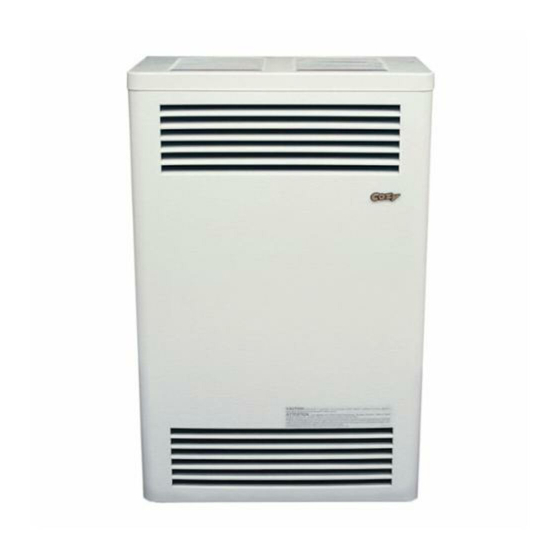
- Page 1 DIRECT VENT WALL FURNACE Installation and Operating Instructions ENGLISH ESPAÑOL FRANÇAIS Haga clic aquí para ver el manual Cliquez ici pour le manuel complet Click here for the full manual or completo o haga clic en los ou cliquez sur les liens ci-dessous click on the links below to quickly siguientes enlaces para localizar pour localiser rapidement ce que...
- Page 2 This appliance is only for use with the type of gas indicated on the rating plate. This appliance is not convertible for use with other gases, unless a certified kit is used. Cozy Heating Systems, LLC | cozyheaters.com | 855-589-5380 | 3230 Industrial Pkwy | Jeffersonville, IN 47130 Page 1...
-
Page 3: Table Of Contents
Back to Index CONTENTS READ CAREFULLY BEFORE INSTALLING UNIT Before Installation These installation instructions are a general guide and do not supersede applicable local codes and ordinances. Before planning Standards ........... 2 or making the installation be sure it complies with all phases of the Specifications ........ -
Page 4: Specifications
Back to Index SPECIFICATIONS & DIMENSIONS Your Direct Vent Wall Furnace is shipped complete in one carton. This carton contains the furnace, vent cap, vent tube, air inlet tube, template with rough-in dimensions, installation and operating instructions, and the thermostat with thermostat wire. NOTE: There will be two cartons if an optional vent kit or blower is purchased. -
Page 5: Venting
Back to Index SAFETY - Continued It is imperative that control compartments, burner, and 20. If it is suspected that rising water may enter the furnace, circulating air passageways of the furnace be kept clean. turn off the gas immediately. Do not use this appliance if any part has been under water. -
Page 6: Clearances
Back to Index CLEARANCES Inside F IX E D Corner B L E C L O S E O P E R A Detail F IX E D C L O S E = Vent Terminal = Air Supply Inlet = Area where terminal is not permitted CANADIAN... -
Page 7: Special Precautions & Location
Back to Index CLEARANCES - Continued 1. If the wall furnace is installed directly on carpeting, tile or any combustible material other than wood flooring, the wall furnace shall be installed on a metal plate or wood panel secured to the floor, extending the full width and depth of the wall furnace. 2. -
Page 8: Standards
Back to Index INSTALLATION WARNING: Failure to follow these instructions carefully could result in poor performance, property damage, personal injury or death. STEP 1. LOCATE VENT OPENING Locate wall studs and center 9” vent opening a minimum of 22” for CDV15 or 24-1/8” for CDV25/33 above the floor. To locate furnace at minimum clearance from floor, remove template from carton and set on floor at location desired. -
Page 9: Back To Index
Back to Index INSTALLATION FOR ALTERNATE WALL DIMENSIONS 9” TO 15" WALLS 15” TO 24” WALLS 9” TO 15” WALLS ( CDV15 / CDV25-C ) ( CDV15 / CDV25-C ) ( CDV33-C ) For 9" to 15" wall use Vent Kit No. For 15" to 24" wall use only Vent Kit For 9” to 15” wall use Vent Kit No. VK33/9- VK1525/9-15-B. -
Page 10: Back To Index
Back to Index INSTALLATION FIG. 4 CDV15-C CDV25/33-C 18" Cabinet 34-1/2" Cabinet 9” Dia. 9" Dia. Opening Opening 9" Valve 29-3/4" 13-3/8" 16-5/8" Inlet 31-3/4" 22" 24-1/8" Valve Inlet 8" 13” 1/2" Floor 4” Shut Off Valve 1/8” N.P.T. 1/2” Min. Center Floor Pressure Tap Line Pipe Elbow... -
Page 11: Gas Connection
Back to Index INSTALLATION FIG. 7 Wall Stud Inside Wall Wall Thimble Extension Wall Thimble Assembly Outside Wall Vent Terminal Spacer Plate Vent Terminal GAS CONNECTION FIG. 8 This heater must be connected to a gas supply capable of supplying the full rated capacity. Provide a 1/8 inch N.P.T. TO HEATER GAS plugged tapping, accessible for test gauge connection, CONTROL VALVE... -
Page 12: Lighting Instructions
Back to Index LIGHTING INSTRUCTIONS MODELS: CDV155C / CDV156C / CDV255C / CDV256C / CDV335C / CDV336C FOR YOUR SAFETY READ BEFORE LIGHTING WARNING: This appliance has a pilot which must be • If you cannot reach your gas supplier, call If you do not lighted by hand. -
Page 13: Maintenance
Back to Index MAINTENANCE WARNING: This is a gas-fired appliance. Keep the area clear of gasoline and other flammable vapors and liquids. All combustible material must be kept clear of this area to avoid fire or explosion. For proper and safe operation keep furnace and furnace If the air intake tube or the exhaust tube is removed, follow area clean. At regular intervals turn control valve to off, Step 3 of the installation section for re-assembly. Be sure to let cool and clean inside control compartment and under check gaskets and replace if there is any sign of damage. -
Page 14: Thermostat Installation
3/8" Inner Mantle THERMOSTAT INSTALLATION Only for Models: CDV155C, CDV156C, CDV255C, CDV256C, CDV335C & CDV336C Follow the instructions included with the thermostat. If the thermostat is to be wall mounted, select a location in the same room as the heater, approximately five feet above the floor on an inside wall where it won’t be affected by heat or cold sources such as direct sunlight, televisions, fireplaces, hidden hot or cold water pipes, drafts, etc. -
Page 15: Service Records
Back to Index MAINTENANCE Label all wires prior to disconnection when servicing controls. Wiring errors can cause CAUTION: improper and dangerous operation. Verify proper operation after servicing. NOTE: The furnace and all components must be inspected at least annually by a qualified service technician. This should include the burner, heat exchanger, and vent system. Be sure that the flow of combustion and ventilation air are not obstructed. FIG. -
Page 16: Troubleshooting Charts
Back to Index TROUBLESHOOTING CHART ( FOR QUALIFIED SERVICE TECHNICIAN ) SYMPTOM POSSIBLE CAUSES CORRECTIVE ACTION Flame 1. Defective operator section of valve. 1. Replace valve. Too Large 2. Burner orifice too large. 2. Check with local gas company for proper orifice size and replace. 3. If installed above 2,000 ft. 3. -
Page 17: Back To Index
Back to Index DVB-3 BLOWER KIT INSTALLATION - ( OPTIONAL ) This kit must be installed by a qualified installer or service technician only. Compatable with CDV15-C / CDV25-C / CDV33-C Series. CAUTION: Label all wires prior to disconnection when servicing controls. Wiring errors can cause improper and dangerous operation. Verify proper operation after servicing. STEP 1. -
Page 18: Back To Index
Back to Index DVB-3 BLOWER KIT INSTALLATION - ( OPTIONAL ) This kit must be installed by a qualified installer or service technician only. Compatable with CDV15-C / CDV25-C / CDV33-C Series. FIG. 15-A LADDER PART DESCRIPTION PART NO. SCHEMATIC BLOWER HOUSING w/ Motor & Blower 70201 JUNCTION 43610 JUNCTION BOX COVER... -
Page 19: Bbsk Installation
Back to Index BBSK INSTALLATION INSTRUCTIONS - ( OPTIONAL ) This kit must be installed by a qualified installer or service technician only. STEP 1. Locate dimple at right rear of the cabinet top. FIG. 16-A See Figure 16-A. 13/16" CDV15 STEP 2. Using dimple as a locator, drill a ½” hole. 3-1/4"... - Page 20 Back to Index BBSK-CDV LIGHTING INSTRUCTIONS - ( OPTIONAL ) FOR YOUR SAFETY READ BEFORE LIGHTING WARNING: This appliance has a pilot which must be • If you cannot reach your gas supplier, call If you do not lighted by hand. When lighting the pilot, the fire department.
- Page 21 Back to Index DIRECT VENT WALL FURNACE PARTS LIST Natural Gas: CDV155C | Propane Gas: CDV156C = 6-3/4” Dia. = 4-3/16” Dia. OPTIONAL VENT EXTENSIONS VK1525/9-15 Vent Kit Assembly VK1525/15-24 Vent Kit Assembly OPTIONAL BLOWER ASSEMBLY / DVB-3 DVB3 Blower Kit also includes: 43078 Cover Plate 43625 Blower Shield for CDV25/33 NOTE: Parts &...
- Page 22 DIRECT VENT WALL FURNACE PARTS LIST Natural Gas: CDV155C | Propane Gas: CDV156C ATTN: Contractors and Qualified Service Technicians: We only sell parts through our wholesalers. For prompt parts service, contact the wholesaler from which you purchased your Cozy heater. PART DESCRIPTION PART DESCRIPTION PART NO.
-
Page 23: Cdv356
Back to Index DIRECT VENT WALL FURNACE PARTS LIST Natural Gas: CDV255C & CDV335C | Propane Gas: CDV256C & CDV356C = 6-3/4” Dia. = 4-3/16” Dia. Ref No. 61, 62 & 63 Not Illustrated. OPTIONAL VENT EXTENSIONS VK1525/9-15 & VK33/9-15 Vent Kit Assembly... -
Page 24: Cdv356
ATTN: Contractors and Qualified Service Technicians: We only sell parts through our wholesalers. For prompt parts service, contact the wholesaler from which you purchased your Cozy heater. Natural Gas Model Numbers .. -
Page 25: Warranty
Back to Index LIMITED WARRANTY Cozy Heating Systems LLC warrants to the original installer, the user should write directly to the manufacturer, user the accompanying product for the period specified and the name of an alternative service source will be supplied. - Page 26 No es posible hacerlo funcionar con ningún otro tipo de gas, a menos que se use un kit (juego) certificado. Cozy Heating Systems, LLC | cozyheaters.com | 855-589-5380 | 3230 Industrial Pkwy | Jeffersonville, IN 47130 Manual Español Página 1...
-
Page 27: Antes De La Instalación Las Normas
Volver al índice TABLA DE CONTENIDO LEA ESTA SECCIÓN ANTES DE INSTALAR LA UNIDAD Antes de la Instalación Este instructivo es una guía general para su aparato y no substituye los códigos y reglamentos locales que aplican. Antes de planear o Las Normas ........ -
Page 28: Especificaciones
Volver al índice ESPECIFICACIONES DEL CALEFACTOR Su calefacción de pared con ventilación directa es embalada completa en un solo cartón. Este cartón contiene la calefacción, tapa para ventilación, tubo de ventilación, tubo de entrada de aire, plantilla con dimensiones, instrucciones de instalación y operación, y el termostato con cable de termostato. - Page 29 Volver al índice REGLAS DE SEGURIDAD - Continuado técnico de servicio calificado. Quizá sea necesario limpiar 20. Si se sospecha que el nivel de agua puede liegar a penetrar el horno, cierre el gas inmedíatamente. No use este aparato con más frecuencia el aparato debido a un exceso de pelusa si alguna de sus partes se ha sumergido en agua.
-
Page 30: Espacios Libres
Volver al índice ESPACIOS LIBRES Detalle de F IJ O la Esquina B L E O P E R A C E R R A F IJ O Interior C E R R A = Terminal de Ventilación = Entrada de Suministro de Aire = Área Donde no se Permite el Terminal Instalaciones... -
Page 31: Espacios Libres
Volver al índice ESPACIOS LIBRES - Continuado 1. Si la calefacción de pared está instalada directamente sobre la alfombra, azulejo u otro material que no sea piso de madera, la calefacción de pared debe ser instalada sobre una placa de metal o panel de madera asegurado al suelo, extendiendo todo el ancho y profundidad de la calefacción de pared. - Page 32 Volver al índice INSTALACIÓN PRECAUCIÓN: El incumplimiento de estas instrucciones con cuidado puede provocar un rendimiento deficiente, daños a la propiedad, lesiones personales o la muerte. PASO 1. UBICACIÓN DE APERTURA PARA LA VENTILA. Ubique los pernos de la pared y centre la abertura de ventilación de 9”, como mínimo, 22” para CDV15 o 24-1/8” para CDV25/33 sobre el piso.
- Page 33 Volver al índice INSTALACIÓN PARA DIMENSIONES DE PARED ADICIONALES INSTALACIÓN DEL CALEFACTOR INSTALACIÓN DEL CALEFACTOR INSTALACIÓN DEL PAREDES DE 22.86 CM A 38.10 CM PAREDES DE 38.10 CM A 60.96 CM CALEFACTOR PAREDES DE ( CDV15 / CDV25-C ) (CDV15 / CDV25-C) 22.86 CM A 38.10 CM (CDV33-C) Para paredes de 22.86 cm a 38.10 cm, utilice El VK1525/15-24-B se utiliza con los modelos...
- Page 34 Volver al índice INSTALACIÓN Illustración 4 CDV15-C CDV25/33-C 45.72 cm 87.63 cm Gabinete Gabinete Apertura Apertura del diametro del diametro 22.86 cm 22.86 cm Entrada 22.86 de Valvula 71.76cm 33.97 42.23 de Gas 80.65cm 55.88cm Entrada 61.28cm de Valvula 20.32 de Gas 33.02cm Llave de...
- Page 35 Volver al índice INSTALACIÓN Illustración 7 Entramado de la Pared Pared Interior Extension del Guardacabo de la Pared Calefactor Ensamble del Guardacabo de la Pared Pared Exterior Placa Espaciadora para la Terminal de la Ventila Terminal de Ventila Conexión del Gas Illustración 8 Este calentador debe estar conectado a un suministro de gas capaz de suministrar la capacidad nominal completa.
-
Page 36: Instrucciones De Encendido
Volver al índice INSTRUCCIONES DE ENCENDIDO MODELOS: CDV155C / CDV156C / CDV255C / CDV256C / CDV335C / CDV336C PARA SU SEGURIDAD LEA ESTE INSTRUCTIVE ANTES DE ENCENDER EL APARATO ADVERTENCIA: Este aparato tiene un piloto que se debe encender compañia de gas. -
Page 37: Ajuste Del Piloto
Volver al índice MANTENIMIENTO ADVERTENCIA: ESTE APARATO FUNCIONA A GAS. MANTENGA EL ÁREA LIBRE DE GASOLINA Y DE OTROS VAPORES Y LÍQUIDOS INFLAMABLES. TODO MATERIAL COMBUSTIBLE SE DEBE MANTENER ALEJADO DE ESTA ÁREA PARA EVITAR QUE HAYA INCENDIOS O EXPLOSION. Para que su calefactor tenga un funcionamiento apropiado y No obstruya el paso del aire para combustión y ventilación. -
Page 38: Instalación Del Termostato
0.9525cm Manto Incandescente INSTALACIÓN DEL TERMOSTATO ÚNICAMENTE PARA LOS MODELOS: CDV155C, CDV156C,CDV255C, CDV256C, CDV335C, CDV336C Siga las instrucciones que vienen incluidas con el termostato. Si el termostato se va a instalar en la pared, elija un lugar en el mismo cuarto que el calefactor, a aproximadamente 1.52 m arriba del piso en una pared interior donde no se vea afectado por fuentes de calor o frío tal... -
Page 39: Registros De Servicio
Volver al índice MANTENIMIENTO Etiquete todos los cables antes de la desconexión al realizar el mantenimiento de PRECAUCIÓN: los controles. Los errores de cableado pueden causar un funcionamiento incorrecto y peligroso. Verificar el funcionamiento correcto después del servicio. NOTA: El calefactor y todos los componentes se deben inspeccionar por lo menos usa vez al año por un técnico de servicio calificado. -
Page 40: Tabla De Localización De Problemas
Volver al índice TABLA DE LOCALIZACIÓN DE PROBLEMAS ( Para ser usado por un instalador o un técnico de servicio calificados. ) SÍNTOMA CAUSAS POSIBLES ACCÍON CORRECTIVA LA LLAMA ESTÁ 1. Sección defectuosa de la válvula. 1. Cambie la válvula. MUY GRANDE 2. - Page 41 Volver al índice INSTRUCCIONES DE INSTALACION PARA EL KIT DEL SPOLADOR DVB-3 - ( OPCIONAL ) Este kit solo debe instalarlo un instalador calificado o un técnico de servicio. Compatible con la serie CDV15-C / CDV25-C / CDV33-C. PRECAUCIÓN: Etiquete todos los cables antes de la desconexión al realizar el mantenimiento de los controles.
- Page 42 Volver al índice INSTRUCCIONES DE INSTALACION PARA EL KIT DEL SPOLADOR DVB-3 - ( OPCIONAL ) Este kit solo debe instalarlo un instalador calificado o un técnico de servicio. Compatible con la serie CDV15-C / CDV25-C / CDV33-C. Illustración 15-A ESQUEMA DESCRIPCIÓN DE LA PARTE NÚM.
- Page 43 Volver al índice INSTRUCCIONES PARA LA INSTALACIÓN DEL KIT BBSK - ( OPCIONAL ) Este kit solo debe instalarlo un instalador calificado o un técnico de servicio. Localice el hoyuelo en la sección trasera derecha de la parte superior del PASO 1.
- Page 44 Volver al índice INSTRUCCIONES DE ENCENDIDO PARA EL MODELO BBSK - ( OPCIONALES ) PARA SU SEGURIDAD LEA ESTE INSTRUCTIVO ANTES DE ENCENDER EL APARATO ADVERTENCIA: SI NO Este aparato tiene un piloto que se debe encender • Si no puede comunicarse con la compañía de gas, SIGUE ESTAS a mano.
- Page 45 Volver al índice LISTA DE PIEZAS - DE HORNO DE PARED DIRECTA Gas Natural: CDV155C | Gas Propano: CDV156C = 17.145 cm Dia. = 10.6299 cm Dia. EXTENSIONES OPCIONALES DEL RESPIRADERO VK1525/9-15 Juego para el Ensamble de la Ventila VK1525/15-24 Juego para el Ensamble de la Ventila MONTAJE DEL VENTILADOR OPCIONAL / DVB-3 DVB-3 VENTILADOR...
- Page 46 Gas Natural: CDV155C | Gas Propano: CDV156C ATTN: Contratistas y Técnicos de Servicio Calificados: Solo vendemos piezas a través de nuestros mayoristas. Para obtener un servicio de piezas rápido, comuníquese con el mayorista al que le compró su calentador Cozy. # RÉF.
-
Page 47: Cdv356
Volver al índice LISTA DE PIEZAS - DE HORNO DE PARED DIRECTA Gas Natural: CDV255C & CDV335C | Gas Propano: CDV256C & CDV356C = 17.145 cm Dia. = 10.6299 cm Dia. # Réf. 61, 62 y 63 No ilustrado EXTENSIONES OPCIONALES DEL RESPIRADERO VK15 / 25-9-15”... -
Page 48: Cdv356
ATTN: Contratistas y Técnicos de Servicio Calificados: Solo vendemos piezas a través de nuestros mayoristas. Para obtener un servicio de piezas rápido, comuníquese con el mayorista al que le compró su calentador Cozy. Números de Modelo de Gas Natural .. -
Page 49: Garantía
Horno Cozy de contratl ujo a gas con tobera directa 10 Años 10 Años Horno de aira eficiencia Cozy de pared, a gas y con tobera directa 10 Años 10 Años Calefactor a gas con ventiladores Cozy de tobera directa a través de muro 10 Años... - Page 50 Cet appareil est uniquement destiné à être utilisé avec le type de gaz indiqué sur la plaque signalétique. Cet appareil n’est pas convertible pour une utilisation avec d’autres gaz, sauf si un kit certifié est utilisé. Cozy Heating Systems, LLC | cozyheaters.com | 855-589-5380 | 3230 Industrial Pkwy | Jeffersonville, IN 47130 Manuel Français...
-
Page 51: Les Normes
Retour à l'index Retour à l'index TABLE DES MATIÈRES LIRE ATTENTIVEMENT AVANT D’INSTALLER DE CETTE L’UNITÉ Ces directives d’installation servent de guide général et ne remplacent Avant L’Installation pas les codes locaux et ordonnances applicables. S’assurer de se Les Normes ........2 confonner à... -
Page 52: Spécifications
Retour à l'index Retour à l'index SPÉCIFICATIONS - GÉNÉRATEUR INDIVIDUEL Votre chaudière murale à prise d’air directe est expédiée en un seul carton. Ce carton contient la chaudière, le capuchon d’aération, le tuyau d’aération, le tuyau d’ admission d’ air, le modèle des dimensions des robinetteries, les instructions d’installation et de fonctionnement et le câble du thermostat. -
Page 53: Ventilation
Retour à l'index Retour à l'index SÉCURITÉ - A Continué nettoyage plus fréquent peut être requis s’ il y a un excès de 20. Si vous suspectez une montée d’eau dans la chaudière, coupez immédiatement le gaz. N’utilisez pas l’appareil si peluche provenant de tapis, literie, etc. -
Page 54: Dégagements
Retour à l'index Retour à l'index DÉGAGEMENTS TERMINAUX DE VENTILATION Coin F IX E Intérieur B L E F E R M É O P É R A Détail F IX É F E R M É = Borne De Passage = Admission D’Air = Secteur ou la Borne N’est Pas Autorisée... -
Page 55: Emplacement Et
Retour à l'index Retour à l'index DÉGAGEMENTS - A Continué 1. Si la chaudière est directement installée sur de la moquette, du carrelage ou tout matériau combustible autre que du plancher en bois, installez-la sur un panneau de bois ou de métal fixé au sol, de la largeur et de la profondeur de la chaudière. 2. - Page 56 Retour à l'index Retour à l'index INSTALLATION ATTENTION: Si ces directives ne sont pas suivies prudemment, il pourrait y avoir comme conséquence un faible rendement, des dommages à la propriété, des blessures ou la mort. ÉTAPE 1 EMPLACEMENT DE L’OUVERTURE DU VENTILATION Déterminer l’emplacement des montants et centrer l’ouvexiure du ventilation de 22,9 mm (9 po) au moins 56 cm (22 po) au-dessus du sol pour un CDV15 et 61 cm (24-1/8 po) pour un CDV25/33.
- Page 57 Retour à l'index Retour à l'index INSTALLATION POUR DES DIMENSIONS DE MUR SUPPLÉMENTAIRES INSTALLATION DE LA INSTALLATION DE LA INSTALLATION DE LA FOURNAISE - MURS 22,86 CM FOURNAISE - MURS 38,10 CM À FOURNAISE- MURS 22,86 CM À À 38,10 CM (CDV15 / CDV25-C) 60,96 CM (CDV15/ CD V25-C) 38,10 CM (CDV33-C) Pour les murs de 22,86cm à...
- Page 58 Retour à l'index Retour à l'index INSTALLATION Schéma 4 CDV15-C CDV25/33-C 45,72 cm 87,63 cm Caisson Caisson Ouverture Ouverture dia. dia. 22,86 cm 22,86 cm Soupape 22,86 D’admission 71,76cm 33,97 42,23 de Gaz 80,65cm 55,88cm Soupape 61,28cm d’admission 20,32 de gaz 33,02cm Robinet 1.27cm...
- Page 59 Retour à l'index Retour à l'index INSTALLATION Schéma 7 Poteau Mural Mur Intérieur Prolongation du Manchon D’emboîtement Mural Manchon D’emboîtement Mural Mur Extérieur Plaque-Entretoise du Tuyau de Ventilation Tuyau de Ventilation ALIMENTATION EN GAZ Schéma 8 Ce radiateur ventilé doit être raccordé à une alimentation en gaz capable de fournir une capacité...
-
Page 60: Instructions Pour L'allumage
Retour à l'index Retour à l'index INSTRUCTIONS POUR L’ALLUMAGE MODÈLES: CDV155C CDV255C CDV335C PAR SOUCI DE SÉCURITÉ, LIRE AVANT D’ALLUMER MISE EN GARDE: Cet appareil est muni d’une veilleuse qui doit être gaz depuis un voisin. Suivez les instructions du SI VOUS NE allumée manuellment. -
Page 61: Entretien
Retour à l'index Retour à l'index ENTRETIEN MISE EN GARDE: Cet appareil fonctionne au gas. Ne pas entreposer ou utiliser de l’essence ou d’autres liquides ou vapeurs inflammables aux alentours de cet appareil. Toute matière combustible doit être gardée loin de cet appareil de chauffage afin d’éviter une incendie ou une explosion. Garder la foumaise et l‘aire de la fournaise propres pour un Ne pas obstruer l’air de combustion et de ventilation. -
Page 62: Orifice Du Brûleur
0,9525cm Maneau Intérieur INSTALLATION DU THERMOSTAT Seulement pour les Modèles: CDV155C, CDV156C, CDV255C, CDV256C, CDV335C & CDV336C Suivre les instructions incluses avec le thermostat. Si le thermostat doit être monté au mur, choisir un endroit dans la même pièce que l‘appareil de chauffage, environ cinq pieds au-dessus du plancher sur un mur intérieur là... - Page 63 Retour à l'index Retour à l'index ENTRETIEN Au moment de l’entretien des commandes étiquetez tous les fils avant le débranchement. ATTENTION: Des erreurs de câblage peuvent entraîner un fonctionnement inadéquat et dangereux. REMARQUE - La fournaise et tous ses composants doivent être inspectés au moins annuellement par un technicien d’entretien qualifié.
- Page 64 Retour à l'index Retour à l'index TABLEAU DE DÉPANNAGE ( A utiliser par un installateur ou un technicien d’entretien qualifié. ) PROBLÈME CAUSE POSSIBLE ACTION CORRECTIVE FLAMME 1. Soupape defective. 1. Remplacer la soupape. TROP 2. Orifice trop grand du brûleur. 2.
- Page 65 Retour à l'index Retour à l'index KIT SOUFFLEUR DVB-3 NOTICE D’INSTALLATION - ( FACULTATIF ) Ce kit doit être installé uniquement par un installateur qualifié ou un technicien de maintenance. Compatible avec les séries CDV15-C / CDV25-C / CDV33-C. ATTENTION: Au moment de l’entretien des commandes étiquetez tous les fils avant le débranchement. Des erreurs de câblage peuvent entraîner un fonctionnement inadéquat et dangereux.
- Page 66 Retour à l'index Retour à l'index KIT SOUFFLEUR DVB-3 NOTICE D’INSTALLATION - ( FACULTATIF ) Ce kit doit être installé uniquement par un installateur qualifié ou un technicien de maintenance. Compatible avec les séries CDV15-C / CDV25-C / CDV33-C. Schéma 15-A SCHÉMA DESCRIPTION DE PIÈCE PIÈCE...
- Page 67 Retour à l'index Retour à l'index INSTRUCTIONS D’INSTALLATION DU KIT BBSK - ( FACULTATIF ) Ce kit doit être installé uniquement par un installateur qualifié ou un technicien de maintenance. Trouver la dépression à l’arrière droit du haut de l’enceinte. ÉTAPE 1.
- Page 68 Retour à l'index Retour à l'index INSTRUCTIONS D’ALLUMAGE DU MODÈLE BBSK - ( FACULTATIF ) PAR SOUCI DE SÉCURITÉ, LIRE AVANT D’ALLUMER MISE Cet appareil est équipé d’une veilleuse qui doit être instructions du fournisseur de gaz. EN GARDE: allumée manuellement. Il faut suivre scrupuleusement •...
- Page 69 Retour à l'index Retour à l'index APPARElL DE CHAUFFAGE MURAL À ÉVACUATION DIRECTE PAR VENTILATEUR - LISTE DES PIÈCES Gaz Natural: CDV155C | Gaz Propane: CDV156C = 17.145 cm Dia. = 10.6299 cm Dia. EXTENSIONS FACULTATIVES D’ÉVENT VK1525/9-15 Assemblage de L’ensemble de Ventilation VK1525/15-24 Assemblage de L’ensemble de Ventilation VENTILATEUR FACULTATIF / DVB-3...
- Page 70 Gaz Natural: CDV155C | Gaz Propane: CDV156C ATTN: Entrepreneurs et Techniciens de Service Qualifiés: Nous ne vendons des pièces que par l’intermédiaire de nos grossistes. Pour un service de pièces rapide, contactez le grossiste chez qui vous avez acheté votre appareil de chauffage Cozy. RÉF.
-
Page 71: Cdv356
Retour à l'index Retour à l'index APPARElL DE CHAUFFAGE MURAL À ÉVACUATION DIRECTE PAR VENTILATEUR - LISTE DES PIÈCES Gaz Natural: CDV255C & CDV335C | Gaz Propane: CDV256C & CDV356C = 17.145 cm Dia. = 10.6299 cm Dia. N o Réf. -
Page 72: Cdv356
ATTN: Entrepreneurs et techniciens de service qualifiés: Nous ne vendons des pièces que par l’intermédiaire de nos grossistes. Pour un service de pièces rapide, contactez le grossiste chez qui vous avez acheté votre appareil de chauffage Cozy. Numéros de Modèle Gaz Natural .. -
Page 73: Garantie
10 Années 10 Années Chauffage à évacuation directe, à contre-courant au gaz Cozy 10 Années 10 Années Chauffage mural à évacuation directe très efficace au gaz Cozy 10 Années 10 Années Chauffage-ventilateur mural à évacuation directe Cozy 10 Années 10 Années COZY HEATING SYSTEMS, LLC 3230 INDUSTRIAL PARKWAY.
Need help?
Do you have a question about the CDV335C and is the answer not in the manual?
Questions and answers