COZY DVCF403C-H Installation And Operating Instructions Manual
Direct vent counterflow
Hide thumbs
Also See for DVCF403C-H:
- Installation and operating instructions manual (73 pages) ,
- Installation and operating instructions manual (72 pages)
Table of Contents
Advertisement
R
24 VOLT SYSTEM WITH LOW-BTU PILOT
MODEL NUMBERS
NAT. GAS
DVCF403C-H
L.P. GAS
DVCF404C-H
INSTALLER: Leave this manual with the
appliance.
CONSUMER: Retain this manual for
future reference.
WARNING: If the information in this manual is not followed exactly, a
fire or explosion may result causing property damage, personal injury or
loss of life.
-
Do not store or use gasoline or other flammable vapors and liquids
in the vicinity of this or any other appliance.
-
WHAT TO DO IF YOU SMELL GAS:
-
Do not try to light any appliance.
-
Do not touch any electrical switch; do not use any phone in your
building.
-
Immediately call your gas supplier from a neighbor's phone. Follow the
gas supplier's instructions.
-
If you cannot reach your gas supplier, call the fire department.
-
INSTALLATION AND SERVICE MUST BE PERFORMED BY A
QUALIFIED INSTALLER, SERVICE AGENCY OR THE GAS
SUPPLIER.
WARNING: Operation of this furnace without the properly installed, furnished vent system and vent cap
could result in Carbon Monoxide (CO) poisoning and possible death. For your safety, this furnace and the
vent system should be inspected at least annually by a qualified service technician.
This unit is for residential use only and is not approved for installation in greenhouses, or environ-
ments involving dusty, wet, corrosive, or explosive conditions. Such conditions will invalidate the
warranty and may create unsafe conditions.
Installation, maintenance, service, troubleshooting and repairs must be performed by a qualified service
agency. Mr./Mrs. Homeowner, DO NOT attempt any of these procedures yourself as this could expose you
to property damage, personal injury or loss of life and will invalidate all warranties.
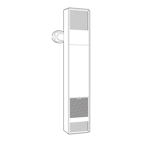
COUNTERFLOW
WALL FURNACE
INSTALLATION AND
OPERATING INSTRUCTIONS
P/N 72900 - REV. 04/2013
DVCF553C-H
DVCF554C-H
DIRECT VENT
24 VOLT SYSTEM W/INTERMITTENT IGNITION (IID)
MODEL NUMBERS
NAT. GAS
L.P. GAS
The coating selected to provide longer life to
the heat exchanger may smoke slightly upon
initial firing. Please provide adequate
ventilation if this occurs.
DVCF407C-H
DVCF557C-H
DVCF408C-H
DVCF558C-H
R
Advertisement
Table of Contents

Related Manuals for COZY DVCF403C-H


Summary of Contents for COZY DVCF403C-H
- Page 1 24 VOLT SYSTEM W/INTERMITTENT IGNITION (IID) 24 VOLT SYSTEM WITH LOW-BTU PILOT MODEL NUMBERS MODEL NUMBERS NAT. GAS DVCF407C-H DVCF557C-H NAT. GAS DVCF403C-H DVCF553C-H L.P. GAS DVCF408C-H DVCF558C-H L.P. GAS DVCF404C-H DVCF554C-H The coating selected to provide longer life to...
-
Page 2: Table Of Contents
Btu/Hr. Gas Blower Approx. Number Control Gas Input Inlet Finished Dimensions Speed Amps Ship. Wt. 24 VOLT SYSTEM WITH LOW-BTU STANDING PILOT DVCF403C-H 24 Volt Nat. 40,000 ½” 14-5/16”Wx78-5/8”Hx11-3/4”D 1.95 130 Lbs. DVCF404C-H 24 Volt L.P. 40,000 ½” 14-5/16”Wx78-5/8”Hx11-3/4”D 1.95 130 Lbs. -
Page 3: Safety Rules
SAFETY RULES 1. This appliance must be installed in accordance with local codes, if any; if not, follow the National Fuel Gas Code, ANSI Z223.1/NFPA 54 or the Natural Gas and Propane Installation Code, CSA-B149.1. 2. Follow all applicable local codes and ordinances. If there are none, follow the latest edition of the National Fuel Gas Code, ANSI.Z223.1. - Page 4 Vent Terminal Air Supply Inlet Area where terminal is not permitted VENT TERMINAL CLEARANCES REFERENCE LETTER TO CANADIAN INSTALLATIONS¹ U.S. INSTALLATIONS² DRAWING A = Clearance above grade, veranda, 12 Inches (30 cm) 12 Inches (30 cm) porch, deck, or balcony B = Clearance to window or door that 12 Inches (30 cm) DVCF40__ 9 Inches (23 cm)
-
Page 5: Clearances
CLEARANCES Ceiling 1. The minimum clearance to a side wall is 4”. (See Fig. 1). NOTE: The unit may be recessed and rest directly against side studs and 4” Minimum the inside surface of the rear wall. 2. The minimum clearance to the ceiling is 4”. (See Figure 1). 3. -
Page 6: Location
LOCATIONS 1. This furnace must be installed on an outside wall and vented to the outside. If possible, this wall should be on the side of the house that receives the least amount of wind since strong gusting winds could cause pilot outage. 2. -
Page 7: Installation
LOCATE VENT OPENING After the location of the heater has been determined, the opening for the vent pipe should be cut. If the heater is to be recessed, cut out opening for heater between studs on the interior wall and cut out the floor plate between the studs, so heater will set flat on floor as all dimensions are given from a finished floor. -
Page 8: Lighting Instructions
LIGHTING INSTRUCTIONS: DVCF403C-H/404C-H, DVCF553C-H/554C-H FOR YOUR SAFETY READ BEFORE LIGHTING WARNING: If you do not follow these instructions exactly, a fire or explosion may result causing property damage, personal injury or loss of life. A. This appliance has a pilot which must be lighted by If you cannot reach your gas supplier, call the fire hand. -
Page 9: Lighting Instructions
LIGHTING INSTRUCTIONS: DVCF407C-H/408C-H, DVCF557C-H/558C-H FOR YOUR SAFETY READ BEFORE LIGHTING WARNING: If you do not follow these instructions exactly, a fire or explosion may result causing property damage, personal injury or loss of life. A. This appliance is equipped with an ignition device which If you cannot reach your gas supplier, call the fire automatically lights the pilot. -
Page 10: Pilot Adjustment
TO REMOVE MAIN BURNER FOR PILOT ADJUSTMENT INSPECTION AND CLEANING Locate the pilot adjustment screw on the valve. The 1. Turn thermostat to lowest setting and allow furnace to cool. pilot flame should surround at least the top 3/8” of the 2. - Page 11 AUXILIARY BLACK LIMIT SWITCH LIMIT SWITCH DVCF553/554C-H DVCF403/404C-H PICTORIAL SCHEMATIC PICTORIAL SCHEMATIC MODEL NO. AMPS MODEL NO. AMPS DVCF553-C-H 3.05 DVCF403C-H 1.95 DVCF554-C-H 3.05 GAS VALVE DVCF404C-H 1.95 GAS VALVE SELECTOR FAN SWITCH FAN SWITCH SWITCH MOTOR MOTOR LIMIT SWITCH LIMIT SWITCH 115 V.A.C.
- Page 12 DVCF407C-H, DVCF408C-H I.I.D. DVCF557C-H, DVCF558C-H DVCF407/408C-H THERMOSTAT DVCF557/558C-H THERMOSTAT POWER PICTORIAL PICTORIAL POWER CORD SCHEMATIC SCHEMATIC CORD WHITE WHITE BLACK MOTOR MOTOR BLACK BLACK BLACK BROWN BROWN BLACK BLUE BLACK BLUE GREEN TRANSFORMER TRANSFORMER BLACK BLACK BLUE BLUE BROWN BROWN PILOT PILOT AUXILIARY...
-
Page 13: Terminal Block Wiring
CAUTION: Label all wires prior to disconnection when servicing controls. Wiring errors can cause improper and dangerous operation. Verify proper operation after servicing. TERMINAL BLOCK WIRING DIAGRAM Fan/Limit Switch (Brown) Fan/Limit Switch (Brown) Power Cord (Black) Power Cord (White) Selector Switch (Red) Transformer (Black) Transformer (Black) -
Page 14: Optional Side Discharge Kit
OPTIONAL SIDE DISCHARGE KITS This kit must be installed by a qualified installer or service technician. ROUGH-INS FOR SIDE DISCHARGE SIDE DISCHARGE ON CASING Install plaster grounds as shown in Figure 9. NOTE: When 1. Use Optional Kit No. 306SR-A. side discharge Kit No. - Page 15 14-PEK KIT INSTRUCTIONS (14’ PLUG EXTENSION KIT) This kit must be installed by a qualified installer or service technician. FOR NON-RECESSED INSTALLATIONS ONLY UNITS WITH TERMINAL BOARD 90 Degree Outside STEP # Corner 1. Turn heater off following Section 3 in “Lighting Instructions”...
- Page 16 TECHNICIANS, we only sell parts through our wholesalers, but the prices listed are for your convenience. For prompt parts service, contact the wholesaler from which you purchased your Cozy heater. NOTE: Parts & schematic draw- I.I.D. CONTROL MODULE ings on current models are shown at HONEYWELL www.cozyheaters.com.
-
Page 17: Parts List
Mr. Contractor, we only sell parts through our wholesalers, but the prices listed above are for your convenience. For prompt parts service, contact the wholesaler from which you purchased your Cozy heater. NOTE: Parts & schematic drawings on current models are shown at www.cozyheaters.com. - Page 18 Mr. Contractor , we only sell parts through our wholesalers, but the prices listed above are for your convenience. For prompt parts service, contact the wholesaler from which you purchased your Cozy heater. NOTE: Parts & schematic drawings on current models are shown at www.cozyheaters.com .
-
Page 19: Trouble Shooting Chart
TROUBLE SHOOTING CHART For use by a qualified installer or service technician. SYMPTOM POSSIBLE CAUSES CORRECTIVE ACTION Flame too large 1. Defective operator section of valve. 1. Replace valve. 2. Burner orifice too large. 2. Check with local gas company for proper orifice size and replace. -
Page 20: Service Record
TROUBLE SHOOTING CHART - Continued For use by a qualified installer or service technician. SYMPTOM POSSIBLE CAUSES CORRECTIVE ACTION Burner won’t turn on 1. Gas valve not turned on. 1. Turn gas valve to “on” position. 2. No voltage to valve. 2. - Page 21 TROUBLE SHOOTING CHART FOR INTERMITTENT IGNITION SYSTEM (I.I.D.) Green LED Flash Code (XxY)ª Indicates Next System Action Recommended Service Action No "Call for Heat" Not applicable None Flash Fast Startup - Flame sense Not applicable None Calibration Heartbeat Normal operation Not applicable None 5 minute Retry Delay...
-
Page 22: Warranty
Cozy Gas Fired Counterflow Furnace 10 Years 10 Years Cozy Gas Fired Counterflow Direct Vent Furnace 10 Years 10 Years Cozy Gas Fired Mobile Home Direct Vent Furnace 10 Years 10 Years Cozy Gas Fired Hi-Efficient Direct Vent Wall Furnace 10 Years 10 Years...
Need help?
Do you have a question about the DVCF403C-H and is the answer not in the manual?
Questions and answers