Table of Contents
Advertisement
Quick Links
RX965QV
LGA775 Socket for Intel®
Core™ 2 Duo/ Pentium® Dual core
Pentium® 4/ Pentium® D/ Celeron 440
uATX Motherboard
User's Quick Start Card
Version 1.03
• Inspect the Package:
One
RX965QV Motherboard
One
40-pin IDE cable
One
SATA Cable
One
SATA Power Cable
One
I/O Shield
One
Driver CD (Manual/Drivers)
One
User's Quick Start Card
• Responsibility:
This manual is provided "As-Is" with no warranties of any kind, it will neither expressed or
implied, including, but not limited to the implied warranties or conditions of this product's
fitness for any particular purpose. In no event shall we be liable for any loss of profits, loss of
business, loss of data, interruption of business, or indirect, special, incidental, or
consequential damages of any kind, even the possibility of such damages arising from any
defect or error in this manual or product. We reserve the right to modify and update the user
manual without prior notice.
WARNING: CMOS Battery Damage
Replace your system's CMOS RAM battery only with the identical CR-2032 3V Lithium-Ion
coin cell (or equivalent) battery type to avoid risk of personal injury or physical damage to your
equipment. Always dispose of used batteries according to the manufacturer's instructions, or
as required by the local ordinance (where applicable). The damage due to not following this
warning will void your motherboard's manufacturer warranty.
Perchlorate Material- Special Handling May Apply.
See
http://www.dtsc.ca.gov/hazardouswaste/perchlorate/
ATTENTION: Incorrect BIOS Setup
If you do not know how to handle BIOS setup or how to set it up properly, it is strongly
advisable that you do not modify any of the settings than otherwise instructed in the User's
Quick Start Card. Even a seemingly small incorrect adjustment or modification in the BIOS
setup can render your system unstable or unusable. The incorrect BIOS setup is not covered
by your motherboard's manufacturer warranty.
• Additional Information:
Additional information on setting this board up can be found in the User's Manual in the
provided CD-ROM. The Online User's Manual and FAQ/Knowledge Base can be found on
our website by visiting our website: http://www.bcmcom.com.
answered in our FAQ/Knowledge Base, visit our forums and post your messages or submit a
new FAQ through FAQ Submittal form for us to add your question in our FAQ with our
answer.
533/800/1066MHz FSB
65nm
http://www.bcmcom.com
RX965QV
If your question is not
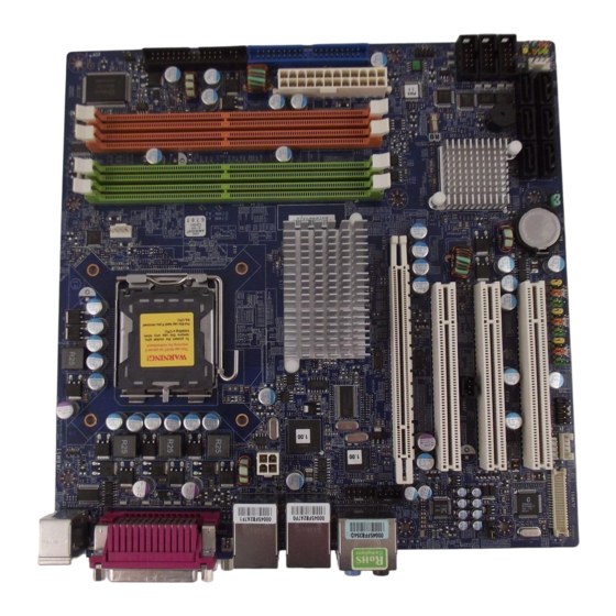
Motherboard Layout:
• Back Panel:
• Board Layout:
Downloaded from StockCheck.com
Advertisement
Table of Contents

Subscribe to Our Youtube Channel
Related Manuals for BCM RX965QV


Summary of Contents for BCM RX965QV
- Page 1 Core™ 2 Duo/ Pentium® Dual core Pentium® 4/ Pentium® D/ Celeron 440 uATX Motherboard User’s Quick Start Card http://www.bcmcom.com Version 1.03 • Inspect the Package: RX965QV Motherboard 40-pin IDE cable SATA Cable SATA Power Cable I/O Shield Driver CD (Manual/Drivers) User’s Quick Start Card RX965QV •...
- Page 2 • Front Panel Connectors: JFP1 WARNING: Electrostatic Sensitive Device (ESD) Static electricity can easily damage your motherboard and will void your motherboard warranty. Keep the motherboard and other system components in their anti-static packaging Signal Description until you are ready to install them. Touch a grounded surface before you remove any system HD_LED+ HD LED+ component from its protective anti-static packaging.
- Page 3 • SATA Ports: SATA1, SATA2, SATA3, SATA4, SATA5, SATA6 • Video Output Select: JPCIE1 Signal PCIEX-16 GRAPHIC CARD LVDS (Default) • Serial Port Connector: COM2, COM3, COM4 • IDE Connector: IDE1 Signal Description Data Carry Datect Receive Data Transmit Data Data Terminal Ready Ground Data Set Ready...
- Page 4 • SPDIF Audio Connector (JSPD1): Signal SPDIF GROUND • Optical Drive Audio Connector: JCD_IN1 • Chassis Intrusion Connector: JCASE1 • Save the Processor Socket Cover After removing the processor cover during processor installation, please save the processor socket cover. In the event that the desktop board needs to be returned for service or any time the processor is removed, the cover should be replaced on the processor socket.
Need help?
Do you have a question about the RX965QV and is the answer not in the manual?
Questions and answers