Table of Contents
Advertisement
Advertisement
Table of Contents

Subscribe to Our Youtube Channel
Related Manuals for Megger S1-552/2


Summary of Contents for Megger S1-552/2
- Page 1 S1-552/2 5kV Digital Insulation Tester USER MANUAL...
-
Page 2: Safety Warnings
SAFETY WARNINGS Safety Warning must be observed during use. The circuit under test must be switched off, de-energised, isolated and checked to be safe before insulation test connections are made. Make sure the circuit is not re-energised whilst the instrument is connected. Circuit connections must not be touched during an insulation test. -
Page 3: Table Of Contents
CONTENTS Safety warnings Test mode summary Introduction Insulation resistance ‘IR’ test General description Breakdown mode / burn mode Features Alarm limit mode Cleaning Step voltage ‘SV’ test Power lead and battery charging Polarisation index ‘PI’ test, and dielectric absorption Instrument controls and indicators ratio ‘DAR’... -
Page 4: Introduction
The S1-552/2 can be powered from the mains supply or by its own The dielectric absorption ratio is automatically calculated if the internal rechargeable battery, which provides for at least 6 hours of corresponding timers are set. -
Page 5: Cleaning
POWER LEAD AND BATTERY CHARGING Cleaning Disconnect the instrument and wipe it with a clean cloth slightly damped with soapy water or Isopropyl alcohol (IPA). If the power lead supplied is not suitable for your mains connection, do not use an adaptor. Always use a power lead fitted with the correct plug. -
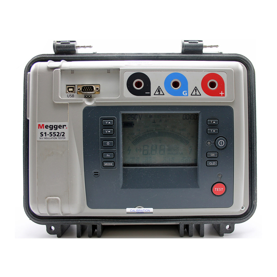
Page 6: Instrument Controls And Indicators
INSTRUMENT CONTROLS AND INDICATORS Line RS232 Measurement terminals Voltage at Test modes Burn indicator Alarm Data recording input guard terminals Time s and Battery level Timers t selectors Main, T1, Voltage s Line input t selectors Present Breakdown Analogue indicator indicator display Power on/off... -
Page 7: Power On/Off Button
Power On/Off button the test voltage is changed during a test, the new test voltage will be The instrument will only turn on if this button is pressed, held and then displayed briefly. When the test has stopped, the display continues to show the voltage released when the display responds. - Page 8 the duration of the test. The digital display toggles between insulation resistance and current. In the ‘IR’, ‘PI’, and ‘DD’ modes the secondary display initially shows the PI (polarity index), DAR (dielectric absorption ratio), and, on completion of the test, the TC (time constant) and capacitance measurements. Toggling the display shows insulation resistances and currents.
- Page 9 Press Ω/I Press Ω/I Press Ω/I Press Ω/I Press Ω/I Press Ω/I Figure 3 - The result of a dielectric discharge test (DD) Figure 2 - The result of a polarity index test (PI) Test settings: T1 and T2 times set in order to measure the DAR Test settings: T1 and T2 times set in order to measure the DAR Test condition: test runs for longer than 10 minutes as this is required Test conditions: timer defaults to 10 minutes, as this is required for a PI...
-
Page 10: Ω/I Button 7 B Button
Figure 4 - The result of a step voltage (SV) test Test condition: timer defaults to 5 minutes and test voltage defaults to Button Press Function Comment 1000 V. Fn + Vs Increment in 10 V steps Voltage range between 50 and 1000 V Fn + Vt Decrement in 10 V steps... -
Page 11: Timer S And T Buttons
Switch the instrument on and wait until initialisation is complete. Hold discharge. Megger Limited cannot accept responsibility for any losses of down the function key and press the record key twice. The instrument data. -
Page 12: Recording To A Pc
Recording to a PC terminal i.e. if the insulator is clean and there are unlikely to be any While carrying out a test, the instrument will output the test voltage, adverse current paths. However in cable testing for example, there may test current and resistance every second. -
Page 13: Rs232 / Usb Connections
If there is an external voltage greater than 50 V present, this will be displayed regardless of changes made to the test voltage. In this case the Programmes such as Megger Download Manager may be used to download the results stored in memory. Programmes such as Microsoft ®... -
Page 14: Analogue Display
‘Pre-Test / During test’ Key action table. display shows the last measurement made until the timer or voltage test settings are changed or the test start/stop button is pressed. Button press Key action Fn + Key action Analogue display Pre-test During test Pre-test During test... -
Page 15: Breakdown Detection
The noise current is either picked up by test leads or induced directly will require switching off and on again to reset. in the item under test. The S1-552/2 and S1-1052/2 are all capable of In certain rare circumstances breakdown of the circuit under test may accurate measurements with up to 3 mA of induced noise current. -
Page 16: Test Mode Summary
TEST MODE SUMMARY Press the ‘MODE’ button to cycle through and select the test mode. Pressing the ‘Ω/I’ button toggles the display to show the insulation Modes of test to be chosen from include an insulation resistance resistances, insulation currents, DAR and PI ratios, and capacitance. The ‘IR’... -
Page 17: Step Voltage 'Sv' Test
the ‘A ’ symbol is flashing on the display. Use the timer s and t minute period. Readings for contaminated insulation are fairly constant buttons to set the resistance threshold between the limits of 10 kΩ and because any absorption effects are masked by high leakage currents. 15 TΩ. -
Page 18: Measurements Above 100 Gω
a few seconds. The other current component, comprising the released Measurements above 100 GΩ absorption current, decays from a lower value with a relatively long time Measurements up to 100 GΩ can be made without any special constant of up to several minutes. If this component of the discharge precautions, assuming that the test leads are reasonably clean and dry. -
Page 19: Circuit Block Diagram
Alternatively, screened leads are available as an optional accessory from For 10 kV instruments C1 = 15 nF, R1 = 156 kΩ, R2 = 110 kΩ Megger. The lead to the negative terminal is fully screened. The screen is plugged into the Guard terminal, diverting any stray leakage currents. -
Page 20: Specifications
<120 ms per µF to discharge from 5 kV to 50 V constant and DD values are also stored if available at the end of the test. Megger Download Manager may be used to transfer this data to a PC. Capacitance measurement (500 V minimum test voltage) -
Page 21: Accessories
Meets the requirements of EN61326-1 HV test lead sets 3 x 3 m with un-insulated small clips 8101-181 Operating uncertainties Refer to www.megger.com 3 x 8 m with un-insulated small clips 8101-182 3 x 15 m with un-insulated small clips 8101-183 Operating temperature -20 °C to 50 °C... -
Page 22: Repair And Warranty
Fax: +1 610 676 8625 Megger operate fully traceable calibration and repair facilities, ensuring your instrument continues to provide the high standard of performance and workmanship you expect. These facilities are complemented by a worldwide network of approved repair and calibration companies to offer excellent in-service care for your Megger products. -
Page 23: Battery Replacement
End of life disposal WEEE The crossed out wheeled bin placed on the Megger products is a reminder not to dispose of the product at the end of it’s product life with general waste. Megger is registered in the UK as a Producer of Electrical and Electronic Equipment. - Page 24 F +41 62 768 20 33 F +91 22 26740465 Megger products are distributed in 146 countries worldwide. This instrument is manufactured in the United Kingdom. The company reserves the right to change the specification or design without prior notice.
Need help?
Do you have a question about the S1-552/2 and is the answer not in the manual?
Questions and answers