
Related Manuals for Megger SPG 5-1000


Summary of Contents for Megger SPG 5-1000
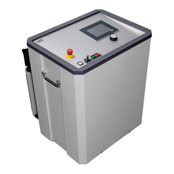
- Page 1 SPG 5-1000 Test and Fault Locating System USER GUIDE Issue: A (03/2023) - EN Article number: 128312766...
- Page 3 E: sales@sebakmt.com Megger This document is copyright of Megger Germany GmbH. The information in this document is subject to change without notice and should not be construed as a commitment by Megger Germany. Megger Germany assumes no responsibility for any errors that may appear in this document.
- Page 4 Terms of Warranty Megger accept responsibility for a claim under warranty brought forward by a customer for a product sold by Megger under the terms stated below. Megger warrant that at the time of delivery Megger products are free from manufacturing or material defects which might considerably reduce their value or usability.
-
Page 5: Table Of Contents
Connecting the HV-line to a faulty cable ....19 4.3.5 Seuring the site and open cable ends ....... 21 4.3.6 Connecting the SPG 5-1000 to the mains ....21 Operation ..............22 Switching On ............22 Rotary Selector ............23 High Voltage HV on .......... - Page 6 Burn Mode ............... 34 Disconnecting electrical connections ....36 Care, Maintenance ..........37 Appendix: Available cable data ..........38...
- Page 7 List of Illustrations Illustr. 1 : FΩ / FU-EP protective device ..........9 Illustr. 2 : Controls ................14 Illustr. 3 : Connections - back ............15 Illustr. 4 : Connection diagram ............16 Illustr. 5 : Connecting to LV cable with sheath ........19 Illustr.
-
Page 8: Introduction
Introduction The SPG 5-1000 has been developed for fault locating in low voltage networks. Its functions are: DC-Testing, Breakdown recognition, Measuring leakage resistance Prelocating ICEplus, Pinpoint locating with step voltage or sound field method, Burning. -
Page 10: Technical Description
Technical Description Technical Data Display 5.7” display (640 x 480) for operating, status- information, input and test results; “one button operation“ Testing 0 ... 5000 V DC; timer Leakage current display 0 ... 1 mA; 0 ... 10 mA; 0 ...100 mA Insulation resistance 1kΩ... -
Page 11: Scope Of Delivery And Options
50 kg (device without access.) 6,5 kg (accessories) Scope of delivery and Options Test and fault locating device SPG 5-1000 Set of cables consisting of: AC mains connection Earthing line (5, 10 or 20 m) High voltage cable (5, 10 or 20 m) - Page 12 Options : External safety with emergency off-switch 820003206 device and signal lights HKZ T9-BE Clamping tongs, black 2013147 ERDOFLEX Earth connection clamp 502021795 NH adapter 700100437 digiPHONE+2 Surge wave receiver 1013124 ESG NT2 Step voltage indicator 1004629-S...
-
Page 13: Safety
Safety General Notes Safety precautions This manual contains basic instructions commissioning and operation of the device / system. For this reason, it is important to ensure that the manual is always available to the authorised and trained operator. He needs to read the manual thoroughly. - Page 14 Labelling of safety instructions The following signal words and symbols are used in this manual and on the product itself: WARNING Indicates a potential hazard which may result in death or serious injury if not avoided. CAUTION Indicates a potential hazard which may result in moderate or minor injury if not avoided.
- Page 15 EN 50191 and national standards and regulations must be strictly adhered to. • The SPG 5-1000 generates a dangerous voltage of up to 5 kV during measurement operation. This is supplied to the test object via a high-voltage cable.
-
Page 16: Safety Devices
Safety devices 3.2.1 FΩ / FU-EP protective device WARNING! The FΩ / FU-EP protective device is used to monitor the resistance between the connection points, but not the connection to earth itself. As described in section 4.3.4, a good connection to all of the earthing points shown in the image is an important prerequisite for safe operation. - Page 17 The resistance between the system and protective earth must not exceed 6 Ω, otherwise the device will not switch to the 'operational readiness' state. The 'Safety circuit' menu appears on the display with the message 'FOHM loop resistance - error'. In some cases, a connection must be established between the protective earth [ a ] and the system earth [ b ] to meet this requirement (see chapter 4.3.4).
-
Page 18: Reverse Voltage Detection
40 and 230 V (50 / 60 Hz) at the HV output, the horn of the SPG 5-1000 sounds. In this case the cable under test needs to be disconnected from the grid as fast as possible! Meanwhile, the SPG 5 1000 must not be put in the “HV stand-by”... -
Page 19: Vde 0104 (En 50191) Clauses
3.3.3 Emergency OFF button Test sites in general have to be equipped with an emergency OFF button. The SPG 5-1000 has a red emergency OFF button on the face plate (see page 14, Illustr. 2). An optional external emergency OFF button, called ‘external safety device’, is available. -
Page 20: Operating
/ test van. Caution! DO NOT TRANSPORT OR OPERATE THE SPG 5-1000 WHEN LYING DOWN because this will lead to safety hazards and damage to the instrument. -
Page 21: Connections And Controls
Connections and controls white green Illustr. 2 : Controls emergency OFF button push-button – white : on/off power switch press : switches the device on, activates system controls lit : device is switched on key switch push-button – green: HV-ON key ... -
Page 22: Illustr. 3 : Connections - Back
Connections on the back - in the transport pouch Illustr. 3 : Connections - back HV-cable connection buzzer (external voltage alarm) 10. connection to earth spike (FU-EP monitoring) 11. connection for external emergency OFF button 12. power output for peripherals (max. 200 watts) 13. -
Page 23: Connecting
Please observe the following procedures for safe operating: 4.3.1 5 Safety Rules Please note the 5 safety rules (or the rules applying to the operator) before connecting the SPG 5-1000 to a test object: 1. turn power off 2. secure against reconnecting 3. -
Page 24: Earthing The Spg 5-1000
4.3.3 Earthing the SPG 5-1000 The SPG 5-1000 has to be earthed before use. To do so connect the protective earth connection [13] to a good safety earth of low resistance (for example, station earth, lighting protection system or other suitable foundation earth electrode) using the earth lead EK1 supplied. - Page 25 Unless reliable earthing can be guaranteed, the entire measurement setup must be considered live. In this case, follow the instructions of the sections related to live working in EN 50110-1. An earthing tester can be used to check the protective earthing.
-
Page 26: Connecting The Hv-Line To A Faulty Cable
4.3.4 Connecting the HV-line to a faulty cable HV-connecting cable (shielded) power cable e.g. with shield FΩ < 6Ω FU-EP Illustr. 5 : Connecting to LV cable with sheath HV-connecting cable (shielded) power cable e.g. without shield FΩ < 6Ω FU-EP Illustr. - Page 27 a) Testing, sound field pinpoint locating, prelocation (ICEplus option) If possible the operating earth of the HV connection line should be connected to the earthed shield of the faulty cable (Illustr. 5). If no sheath is available, or in case of a ‘phase – phase fault’, the operating earth should be connected to one of the two faulty conductors.
-
Page 28: Seuring The Site And Open Cable Ends
(tees) are cordoned off and protected. 4.3.6 Connecting the SPG 5-1000 to the mains Now the SPG 5-1000 can be connected to the mains. Make sure that the mains voltage is the same as the supply voltage of the SPG 5-1000 (230 V AC or 115 V AC). -
Page 29: Operation
Operation Switching On Press the white push button [2] to start the SPG 5-1000. The white push-button lights up. The control and safety circuits are activated and system controls switches the operating menu on. The device will automatically go on ‘stand-by’, the green push-button lights up [4]. -
Page 30: Rotary Selector
Rotary Selector Turn select Press confirm (enter function) Modes are selected in the menu by turning, and activated by pressing the rotary selector [6]. Within a function values are changed by turning. To confirm the selected settings the rotary selector [6] has to be pressed again (ENTER). -
Page 31: Functions
Functions Setup- Menu In the setup-menu the menu language can be changed. Safety Menu Safety Circuit FOHM loop resistance error FU-EP monitoring Emergency Off Switch External Emergency Off Switch Key switch Thermo monitoring System back clear Illustr. 8 : Menu safety circuit The Safety Menu will appear automatically if there is some sort of error. -
Page 32: Test Mode
Test Mode Test 166 kΩ 1990 V 12 mA Output voltage leakage current 0 – 100 mA 2000 V testing time timer on 45 min max. voltage remaining time back HV-ON 12:52 min push green button HV-OFF time is running test over, no breakdown time stopped, no breakdown occurred Illustr. -
Page 33: Insulation Resistance
If a breakdown occurs during testing the SPG 5-1000 will not switch off automatically but will continue to show the insulation resistance. See following paragraph for conditions. 6.3.1 Insulation resistance Insulation resistance is shown on the top right corner of the display as soon as a minimum voltage of 100 V and a minimum current of 10 µA are measured. - Page 34 The information line at the bottom of the display will show “breakdown has occurred” and the SPG 5-1000 will turn off the high voltage. If no breakdown occurs the high voltage remains on. 5. Turn off with the field “HV-OFF” or by pushing the red...
-
Page 35: Prelocating Function
Prelocating function The ICEplus locating function was calibrated at the factory using the provided HV connection cable. Using a HV cable of a different length can negatively impact the accuracy of the measurement result. The ICEplus method (patent pending) is used for prelocating. This method is not influenced by branches (tees) in LV networks. - Page 36 Operating : Precondition: Light in green button [4] on. Select “prelocating” in main menu. Choose field “cable data” on the display as shown Illustr. 11 : Menu Prelocating cable data Under “cable input” (at the top) select one of the following: “accept old cable data”...
-
Page 37: Illustr. 12 : Menu Prelocating
Confirm the cable data input by pressing “continue”. Another menu opens, as shown in Illustr. 12. Prelocating 4 kV range ICEplus 2000 V output voltage 2000 V 460 m single pulse max. voltage fault length back HV - ON HV - OFF Illustr. -
Page 38: Pinpointing Mode
Pinpointing Mode There are two kinds of pinpoint locating to choose from: The sound field method with a surge wave generator with voltage ranges 0 ... 2 kV and 0 ... 4 kV. The step voltage method with a DC output voltage 0 … 5 kV, which can be pulsed. - Page 39 Operating : Precondition: Light in green push-button [4] on. Select ‘pinpointing’ in main menu. Activate field ‘sound field’. After pre-selecting voltage range 2 / 4 kV the above menu (Illustr. 13 : Menu pinpointing - acoustic) appears. Note: The impulse energy is 1000 J at full voltage in the respective selected range.
-
Page 40: Step Voltage Method
6.6.2 Step Voltage Method Pinpointing - Step voltage 420 V 80 % output voltage output current 1000mA 2500 V 80 % max. voltage max. current timing back HV-ON HV-OFF push green button Illustr. 14 : pinpoint locating - Step voltage Operation : Precondition: Light in Green button on [4]. -
Page 41: Burn Mode
Set max. current. When menu is called up the max. current is automatically set at 10% but can be changed manually. In case of automatic change to a different voltage range the percentage value remains unchanged, which means that a lower voltage range will produce a higher current and the percentage value of the max. - Page 42 Manual burn is set as standard where the operator has to enter voltage and burn current himself. If the SPG 5-1000 is in automatic burn mode it automatically switches from the pre-set maximum voltage to the next smallest voltage range as soon as the burn voltage is lower than the next lower range for two seconds.
-
Page 43: Disconnecting Electrical Connections
Disconnecting electrical connections WARNING! When disconnecting the test system, proceed in reverse sequence to the manner in which the connection (see page 16) was made. The following safety instructions must be strictly adhered to: • Follow the five safety rules. •... -
Page 44: Care, Maintenance
Care, Maintenance The lithium battery in the SPS control unit of the SPG 5-1000 saves the RAM data and should be changed after approx. five years at a Megger service centre. If the battery is discharged the SPG 5-1000 will only run in the demonstration mode without high voltage. -
Page 45: Appendix: Available Cable Data
Appendix: Available cable data Type Description Connection options Three-wire cable with copper or aluminium conductors; shield also made of copper or aluminium (no steel sheath) Cross-section (in mm ): 6, 10, 16, 25, 35, 50, 70, 95, 120, 150, 185, 240, 300 Four-wire cable with copper or aluminium conductors;... - Page 46 Type Description Connection options Street lighting cable (twin cable without shield and without sheath) Cross-section (in mm2): 2x10, 2x16 Four-wire cable with copper or aluminium conductors (neutral conductor with smaller cross- section) FE… steel sheath shield Cross-section (in mm ): 3x95+1x50, 3x150+1x95, 3x240+1x95 Four-wire cable with copper or aluminium conductors...
- Page 48 Tento symbol indikuje, že výrobek nesoucí takovéto označení nelze likvidovat společně s běžným domovním odpadem. Jelikož se jedná o produkt obchodovaný mezi podnikatelskými subjekty (B2B), nelze jej likvidovat ani ve veřejných sběrných dvorech. Pokud se potřebujete tohoto výrobku zbavit, obraťte se na organizaci specializující se na likvidaci starých elektrických spotřebičů...
Need help?
Do you have a question about the SPG 5-1000 and is the answer not in the manual?
Questions and answers