Table of Contents
Advertisement
Quick Links
ST25-30-UG-EN-V03
User Manual
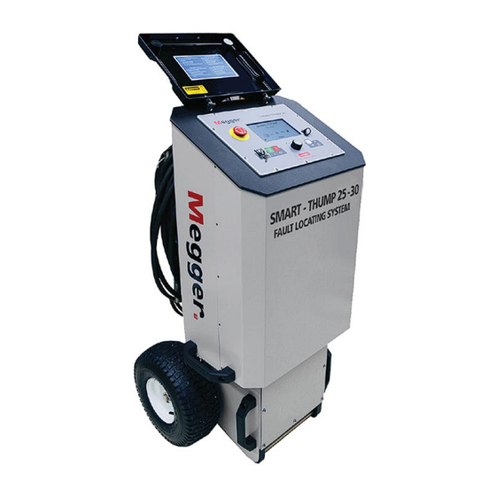
Portable / Vehicle Mounted
Fault Locating System
SMART THUMP ST25-30
covering units with and without
MULTI SHOT Capability
Read this entire manual before operating.
M
Valley Forge Corporate Center
2621 Van Buren Avenue
Norristown, PA 19403-2329
U.S.A.
610-676-8500
www.megger.com
Advertisement
Table of Contents


Need help?
Do you have a question about the SMART THUMP ST25-30 and is the answer not in the manual?
Questions and answers