Table of Contents
Advertisement
Advertisement
Table of Contents

Related Manuals for Megger SG32-1500M


Summary of Contents for Megger SG32-1500M
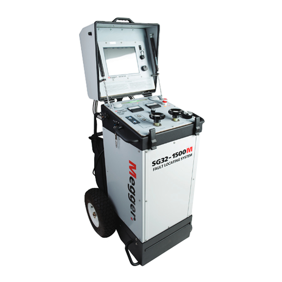
- Page 1 SG32-UG-EN-V01 Dec 2016 User Guide SG32-1500M Megger Portable Cable Fault Locator HIGH VOLTAGE EQUIPMENT Read this entire manual before operating EN 61326 Valley Forge Corporate Center 2621 Van Buren Avenue Norristown, PA 19403-2329 U.S.A. 610-676-8500 www.megger.com...
- Page 3 SG32-1500M Megger Portable Cable Fault Locator...
- Page 4 WARRANTY Products supplied by Megger are warranted against defects in material and workmanship for a period of one year following shipment. Our liability is specifically limited to replacing or repairing, at our option, defective equipment.
- Page 5 Safety Voltages of greater than 50 V applied across dry unbroken human skin are capable of producing heart fibrillation if they produce electric currents in body tissues which happen to pass through the chest area.[citation needed] The electrocution danger is mostly determined by the low conductivity of dry human skin.
-
Page 7: Table Of Contents
2 GETTING TO KNOW YOUR SG32-1500M ................. 7 Basic Operating Principle of User Interface ..................7 All Controls ............................7 Overview of Methods available on the SG32-1500M ................ 7 TDR / Pulse Reflection ........................7 Arc Reflection ............................7 ... - Page 8 Switching On ............................23 Connection Diagram ........................... 24 5 OPERATION OF THE SG32-1500M .................... 25 Test Modes .............................. 25 Connections ............................25 Switching on the unit ..........................26 Test Procedures ............................26 D.C. Dielectric withstand (Proof) Test .................... 26 ...
- Page 9 Prior to operation, check for loosened hardware or damage incurred during transit. If these conditions are found, a safety hazard is likely, DO NOT attempt to operate equipment. Please contact Megger as soon as possible. Please check your delivery against: a) your order...
- Page 10 Standard Manual Conventions This manual uses the following conventions: Bold indicates emphasis or a heading. NOTE: is used to set off important information from the rest of the text. A WARNING symbol alerts you to a hazard that may result in equipment damage, personal injury, or death. Carefully read the instructions provided and follow all safety precautions.
-
Page 11: Specifications
SPECIFICATIONS Supply Input Voltage source SG32-1500M-xx is fitted with a universal input power supply and as such can be supplied from 108-265V AC Power supplies. 2 each fuses, 12A slow blow, for 120V operation are installed if operated from 230V please install 2 each 6A slow blow fuses provided in the accessory bag ... -
Page 12: Surge Impulse (Voltage Impulse)
Surge Impulse (Voltage Impulse) Ranges Two (2) Impulse voltage 0 to 16 kV 0 to 32 kV Impulse Energy @ 100% of range 1500 joule @ 0 to 16 kV 1500 joule @ 0 to 32 kV Impulse Repetition Rate Single Shot 1 to 15 seconds Arc Reflection &... -
Page 13: Low Voltage
SPECIFICATIONS LOW VOLTAGE MTDR 100 (Time Domain Reflectometer, built into lid) Operation Single Jog-Dial Modes Pulse Echo, Direct, Comparison, Arc Reflection, Arc Reflection Multi-shot, Differential Arc Reflection (DART) Impulse Current Ranges 10 ranges: 100 m to 55 km ; 328 ft to 180,445 ft Pulse Width 50 ns, 100 ns, 200 ns, 500 ns, 1 μs, 2 μs, 5 μs, 10 μs Pulse Amplitude... -
Page 14: Safety
Safety Certification to CE 61326 F-OHM Safety Interface, ensures correct and low resistance grounding Key Interlock Prevents unauthorized switching to HV ON Dimensions & Weights Height 965 mm / 38 inches Width 536 mm / 21 inches Depth 503 mm / 20 inches Weight (Total) 131 kgs / 290 lbs Accessories... -
Page 15: Optional (Not Supplied As Standard)
Optional (not supplied as standard) High Resistance Fault Pinpointer Digiphone Plus Cable Reels / Rack Systems Megger have several cable drums and cable drum assemblies which need to be specified dependent on installation and possible combination with other instruments. Another consideration is where the equipment is installed into a vehicle or trailer the available payload must be taken into consideration. - Page 16 SG32-UG-EN-V01 Dec 2016...
-
Page 17: Getting To Know Your Sg32-1500M
The guiding principle for when working with this type of HV equipment. operation of the SG32-1500M is to always push the lit button to go to the next step. Overview of Methods available on the SG32-1500M... -
Page 18: Differential Arc Reflection (Dart)
Differential Arc Reflection (DART) In Differential Arc Reflection mode unwanted and confusing reflections are removed leaving a clean trace with only the fault position being displayed by a positive pulse (HV trace is mathematically subtracted from LV trace). This method can be helpful in locating high-resistance faults in complex cable systems;... -
Page 19: Top Panel Controls
GETTING TO KNOW YOUR SG32-1500M Top Panel Controls 2. Warning Lamp 3. Warning Lamp 1. Warning Lamp 4. Warning Lamp 5. Warning Lamp Zero Start Interlock Check Grounds Check Key Switch Check Mode Switch Check Range Switch 6. High Voltage Key Switch 22. - Page 20 This switch acts as an Emergency Stop, and removes SWITCH AC Power from the unit. To disengage the Emergency Stop and turn on the SG32-1500M, turn the knob clockwise. Push this switch to turn off the SG32-1500M, either in an emergency or when all operations are complete.
- Page 21 GETTING TO KNOW YOUR SG32-1500M SAFETY INTERLOCKS: input 120 or 230V are available at the of the SG32- 1500M. 12. ZERO START POSITION The Voltage Control knob must be in this (zero) position before the HV ON button can be pushed in order to start HV in any of the modes.
-
Page 22: Metering
SG32-1500M is powered or not. After pushing HV OFF or after turning the SG32-1500M completely off, always check that the kV meter indicates ZERO, this indicates that the HV-output cables as well as the test object have been discharged. -
Page 23: External Connections
WARNING NEVER drive a separate ground rod / earth rod and connect the earthing / safety ground lead of the SG32-1500M to it! SG32-UG-EN-V01 Dec 2016... -
Page 24: External Connections Cont'd
24. 2 x Fuse Compartment 23. 120/230 AC Supply Socket SG32-1500M is fitted with a wide range input power supply, AC SUPPLY SOCKET and as such can be supplied from any voltage between 108 and 265Volts (correct fuses must be installed). -
Page 25: Integrated Mtdr
28. PNEUMATIC LID A pneumatic ram provides a safe support during the STRUD opening and closing of the lid of the SG32-1500M. 29. ON / OFF SWITCH A separate AC Power On/Off Switch for the MTDR. 30. USB PORT USB port to download/upload memorized traces including all parameters. - Page 26 SG32-UG-EN-V01 Dec 2016...
-
Page 27: Safety
Handling Guidance IMPORTANT Due to the overall weight and size of the SG32-1500M, it is not designed for manual lifting or carrying. Any lifting should be undertaken with appropriate mechanical equipment, preferably on a level, stable secure platform that can accommodate the wheels and the base of the unit. - Page 28 Only “Competent” or “Authorized” personal should operate the SG32-1500M system. Authorized Person: means a person recognized by an Authorizing Officer as having sufficient technical knowledge to perform certain duties in respect of defined electrical systems and equipment. An Authorized Person is normally appointed in writing by an Authorizing Officer.
-
Page 29: Safety In Using The Sg System
Safety in Using the SG System Never assume that either the SG32-1500M High Voltage Output Cable or the Cable Specimen is de-energized. Always treat exposed conductors and connections as potential electric shock hazards. - Page 30 SG32-UG-EN-V01 Dec 2016...
-
Page 31: Preparing For Test
PREPARING FOR TEST IMPORTANT SAFETY WARNINGS WARNING The HV Return cannot be used as a substitute unit safety ground. Failure to follow this procedure can result in serious injury or in the extreme, death of the operator and/or the destruction of the equipment. -
Page 32: Making Connections
Earth (Ground) the Instrument Prior to operating the SG32-1500M or making any other connections the unit has to be Earthed/Grounded. This is achieved by connecting the supplied Earth... -
Page 33: Hv-Return / Sheath / Concentric Connection
Switching On Once all connections incl. the AC line connection have been made and a safety zone established, the SG32-1500M is automatically powered (white LED comes on instantaneously if the emergency stop button was fully released before). The white LED confirms that line power is present, but the PLC, which controls the SG32 unit, is not energized. -
Page 34: Connection Diagram
Connection Diagram NOTE: If the SG32-1500M is mounted in a vehicle or trailer, the vehicle or trailer must be grounded/earthed to the system ground of the switchgear. The SG32-1500M must be grounded to the same system ground. Do NOT ground the SG32-1500M to a separate ground rod. -
Page 35: Operation Of The Sg32-1500M
OPERATION OF THE SG32-1500M Test Modes The SG32-1500M system provides the User with the following testing and cable fault locating modes: D.C. Dielectric Withstand (Proof) D.C. Proof/Burn TDR (Time Domain Reflectometer, Pulse Echo) Low Voltage Pre-location Arc Reflection Multi-shot - High Voltage Pre-location ... -
Page 36: Switching On The Unit
Test Procedures D.C. Dielectric withstand (Proof) Test The SG32-1500M generates a DC test voltage of 0 to 32 kV with a current of 0 to 40mA (16kV range) and 20mA (32kV range). The proof test is used to check the integrity of cable installations. The test voltage is defined by the user and local regulations. -
Page 37: D.c. Dielectric Proof/Burn
OPERATION OF THE SG32-1500M 2. Set the Voltage Range switch (item 18) to the desired range either 16 or 32kV. 3. Set the rotary Test Mode knob (item 17) to the PROOF/BURN & SURGE test Modes. Both PROOF/BURN & SURGE test Mode pushbutton’s Blue LEDs will illuminate, indicating that either of these test modes are now available for selection. - Page 38 2. Set the Voltage Range switch (item 14) to the desired range either 16 or 32kV. 3. Set the Test Mode selector switch (item 16) to the PROOF/BURN & SURGE group. Both pushbuttons’ Blue LEDs will illuminate, indicating that either of these test modes are available. 4.
-
Page 39: Tdr / Pulse Echo (Time Domain Reflectometer) Low Voltage Tdr Pre-Location
OPERATION OF THE SG32-1500M TDR / Pulse Echo (Time Domain Reflectometer) Low Voltage TDR Pre-location The SG32-1500M has an integrated TDR. 1. Set the rotary High Voltage Control Knob (item 12) to the “Zero Start” position. If the rotary High Voltage Control Knob (item 12) is not set to the “Zero Start”... -
Page 40: Arc Reflection / Arc Reflection Multi-Shot - High Voltage Pre-Location
Arc Reflection / Arc Reflection Multi-Shot - High Voltage Pre-location A Differential Arc Reflection (DART) 1. Set the rotary High Voltage Control Knob (item 12) to the “Zero Start” position. NOTE: If the rotary High Voltage Control Knob (item 12) is not set to the “Zero Start”... -
Page 41: Ice / Current Impulse (Surge Impulse) - High Voltage Prelocation
The features and benefits of "Multi-Shot" and "Differential Arc Reflection (DART)" and how to configure them are described in Addendum 3 - MTDR100 User Guide. The SG32-1500M is operated in both Arc Reflection methods identically 12. Pushing the HV OFF button (item 9) will discharge the selected test voltage. - Page 42 NOTE: The position of the Voltage Range and Test Mode switches cannot be changed while a particular test mode is activated (mechanical interlock). 3. Set the SELECT (test) Mode knob (item 16) to the SURGE & PROOF/BURN test group. Both buttons blue LEDs will illuminate, indicating that either of these test modes are available.
-
Page 43: Surge Generation (Surge Impulse) - High Voltage Pinpoint Location
(item 22). The fault is then pinpointed using an acoustic / magnetic combination pinpointing unit like Megger’s Digiphone Plus. 8. To turn HV off, push the HV OFF button (item 9), which will discharge the entire test circuit. The HV OFF pushbutton’s Red LED will extinguish and... -
Page 44: Switching Off The Unit
4 available test modes. Switching off the unit 1. The PLC inside the SG32-1500M will be de-energized by pushing the ON/OFF pushbutton (item 11; in this state the AC line voltage is still being distributed to the EMERGENCY STOP button and the 24V internal power supply, the unit is in a “power stand-by”... -
Page 45: Maintenance
MAINTENANCE Due to the nature of the SG32-1500M and the high voltages and energy levels present in the instrument, it is recommended that any maintenance is undertaken by a Megger Authorized Service Center. Operators should inspect all connections and cables prior to operation, and in the event of damage should either make a quality repair locally or have the problem repaired via a Megger Authorized Service Center. - Page 46 11. Any signs of mechanical damage? 12. Any signs of water ingress or water damage? 13. How long had the unit been operating before it failed? 14. Local conditions: i.e. weather, temperature, humidity, dust, etc. 15. Contact details of operator, or who to contact to follow-up SG32-UG-EN-V01 Dec 2016...
-
Page 47: Addendum 1: Cable Fault Location Applications Guide
ADDENDUM 1 Cable Fault Location Applications Guide SG32-UG-EN-V01 Dec 2016... - Page 48 Methodical Approach to Cable Fault Locating Megger’s Logical Approach Continuity Insulation Resistance Proof Test = 0-300Ω (approx) = > 300Ω (approx) Low Resistance Fault Fault Diagnosis High Resistance Fault Pulse Echo Method (TDR) Arc Reflection Method Impulse Current Method (ICE)
-
Page 49: Typical Fault Locating Strategy
ADDENDUM 2 Typical Fault Locating Strategy The most important aspect of locating a cable fault is the development of a strategy that will allow the fault location to be safely and positively identified. This is achieved by following the “Methodical Approach to Cable Fault Location”, see previous flowchart. - Page 50 a “dead short” to earth/ground that would be extremely difficult, if not impossible to pinpoint using acoustic methods. c. Another effective method of HV Pre-location is the ICE / Impulse Current method also known as Impulse Surge. This method is effective for pre-locating high-resistance faults (arc resistance greater than 200Ω) where the Arc Reflection method does not work effectively.
-
Page 51: Overview Of Fault Pre-Location Methods
Typical Fault Locating Strategy Overview of Fault Pre-location Methods Description of TDR (Pulse Echo) Techniques TDR also known as Pulse Echo or Radar method for cable fault location use low-voltage pulses to locate changes in impedance along the length of the cable. From these low-voltage pulses, a small amount of energy is reflected back to the TDR as the result of a change in impedance of the cable. -
Page 52: Description Of Arc Reflection
Description of Arc Reflection The Arc Reflection method is based on standard TDR techniques to prelocate high resistance faults, which are not identifiable using TDR by itself. SG32 Surge Generator Thumper In Arc Reflection we use an Impulse Generator, Arc Reflection Filter and the MTDR100. -
Page 53: Description Of Ice / Impulse Current
Typical Fault Locating Strategy Description of ICE / Impulse Current ICE or Impulse current is probably one of the oldest methods of fault Pre- location using “transient analysis”. This method allows the pre-location of high resistance and flashing faults, with the advantage of the HV pulse being effected by any type of filter (100% surge energy), but the disadvantage of not seeing the start and the end of the cable. -
Page 54: Description Of Voltage Decay
Description of Voltage Decay (not integrated in the SG32) Voltage Decay is only used in case of high resistance and high flash-over type faults, if the voltage of the surge capacitor is not sufficient any more to reach the flash-over voltage. Because the Decay mode uses the cable as the HV capacitor, the charging voltage (provided by a HV DC source) should be in excess of 40kV in order to have a reasonable amount of energy stored in the cable (E=1/2 C x U2 ). -
Page 55: Addendum 3: Mtdr100 User Guide
ADDENDUM 3 MTDR100 User Guide SG32-UG-EN-V01 Dec 2016... - Page 56 SG32-UG-EN-V01 Dec 2016...
-
Page 57: Mtdr100 Specification
MTDR100 Specification Operation Jog-Dial Modes Single-Phase Low Voltage Prelocation TDR / Pulse Echo High Voltage Prelocation Arc Reflection Multi-shot, Differential Arc Reflection (DART), Impulse Current (ICE) ICE Loop On Loop OFF Ranges 10 ranges: Pulse Echo Auto, 100m to 55km / 328ft to 34miles Transient Analysis 100m to 200km / 328ft to 137miles 50ns, 100ns, 200ns, 500ns, 1μs, 2μs, 5μs, 10μs... - Page 58 Dimensions (integrated into 406.4mm x 419.1mm x 241.3mm hood) (16 in x 16.5 in x 9.5 in) Weight 6.7 kgs (14.7 lbs) Temperature Operating: -4 to +122F (-20C TO +50C) Storage: -4 to +133F (-20C TO +55C) Humidity < 95 percent none condensing SG32-UG-EN-V01 Dec 2016...
-
Page 59: Getting To Know Your Mtdr100
Getting to know your MTDR100 1. TDR Display 2. USB Port 3. Jog-Dial 1. TDR Display: Large 26mm (10.4”) full XGA display. Displaying all parameters and the necessary information and traces to achieve rapid accurate fault location. 2. SB Port: USB port to download/upload memorized traces including all parameters, and to upgrade system. -
Page 60: Methods Available On The Mtdr100
Methods available on the MTDR100 TDR / Pulse Echo TDR or Pulse Echo is a low voltage method of fault pre-location suitable for locating short and open circuits and other faults below approximately 300Ohms. It is not suitable for high impedance or flashing faults, where HV method should be used. -
Page 61: Loop-Off / Loop-On
Getting to know your MTDR100 Loop-off / Loop-on In this method, which uses the standard Current Impulse techniques, two traces are recorded and compared. For this method to work there must be a 2 or 3 phase circuit available with at least one good core As in standard Current Impulse a flashover is created using the surge generator (thumper) and recorded on the MTDR. -
Page 62: Status Bar
Status Bar HV Trace # 1. Cable Type: Selected from cable library, or custom cable put in by operator 2. Vp: Velocity factor, set by operator or by default setting in cable library 3. Pulse: Pulse width, either set automatically with range or manually by operator 4. -
Page 63: Operator Menu Bar
Getting to know your MTDR100 Operator Menu Bar TRIGGER ON LIVE TRACE HV Trace # Range: Allows operator to select required range. Auto Note: In TDR & ARC Reflection mode with activated (by depression of jog-dial) the system will automatically set the right cursor over end of cable and set range. -
Page 64: Single Button Operation
Single Button Operation Rotary Jog-Dial Operation of the MTDR100 is undertaken via the rotary jog-dial. Selection of modes and setting of all user-defined parameters are easily undertaken with this single control. Selection of the required parameter or settings is obtained by rotating the jog- dial, through the available menus and sub-menus. -
Page 65: Operation Of The Mtdr100
OPERATION OF THE MTDR100 On the SG32-1500M ensure the rotary Voltage Control knob (item 12) is set to the "Zero Start" position. Unless using HV methods of Pre-location the Voltage Range switch (item 14) can be set to any range. If using HV methods of Pre-location this Voltage Range switch (item 14) is to be set to the desired range either 16 or 32kV. -
Page 66: Initial Set-Up
Initial Set-up Important: When you receive your instrument or following an update you will be asked if it is an MTDR100. Please answer as MTDR100 as this will select the correct settings. When you receive the instrument it will have certain parameters pre-set as the “default”. - Page 67 OPERATION OF THE MTDR100 You will then be presented with the following options: Language: Allows the operator to select the operating language from those installed. Velocity Units: The operator can select from: %; ft/µS; m/µS. The Distance Units are automatically changed to the appropriate unit of measurement.
- Page 68 You will then be presented with the following options: The MTDR comes with a standard data-base of “typical” cables. These can be selected by scrolling down and clicking/selecting the one desired. This will then automatically set the cable type and velocity factor for all measurements taken on that setting.
- Page 69 OPERATION OF THE MTDR100 Defaults: Allows Operator to load and save default settings for; TDR, Arc Reflection, Current Impulse, Loop Off / Loop On. Displayed default sub-menu is dependent on Mode setting. Save Defaults: In this submenu you save the default settings for the selected Mode.
- Page 70 Set Cursor Offset: Allows the operator to “null out” the instrument’s output cable. When “nulled out”, the left cursor will be placed at the start of the test object. If selected, this will be set as a default until reset! NOTE: DO NOT use this option in Current Impulse.
- Page 71 OPERATION OF THE MTDR100 Scroll to File” select by depressing jog- dial, you will then be presented with the following sub-menu options: Save: Allows the operator to save current trace with its parameters to internal memory. If “new” selected operator will be presented with a virtual keyboard allowing entry of new name and other pertinent information.
- Page 72 To select Mode (Method) Scroll to “Mode” (also known as method), to configure the MTDR. Select the desired mode by rotating the job-dial until “Mode” is highlighted. Then by depressing the jog- ARC Reflection Multi-shot dial, you will then be presented with the following sub-menu options: Voltage Decay ...
-
Page 73: Arc Reflection Multi-Shot
OPERATION OF THE MTDR100 Arc Reflection Multi-shot ONLY available following a just finished Arc Reflection measurement or after loading a stored Arc Reflection trace from memory. In Arc Reflection Multi-shot, the HV Trace # operator is able to scroll through up to 1028 (dependent on range) Arc Reflection traces, taken during the arc period. - Page 74 NOTE: If the Cable length is known, then Velocity can be verified. Place the left cursor at the start of the cable and the right cursor at the Cable end and adjust the Velocity. When the Distance shown for the right cursor matches the known Cable length, the velocity is set to its correct value.
- Page 75 Megger Quality System Certificate SG32-UG-EN-V01 Dec 2016...
- Page 76 SG32-UG-EN-V01 Dec 2016...
Need help?
Do you have a question about the SG32-1500M and is the answer not in the manual?
Questions and answers
How can i find a foulty cable in the ground
To find a faulty cable in the ground using the Megger SG32-1500M, follow these steps:
1. Preparation:
- Ensure the test area is dry, free from flammable materials, and well-ventilated.
- Identify the faulty cable and gain access to both ends.
- Set up safety barriers and warning lights to protect personnel.
- Verify that the station ground impedance is less than 5 Ohms.
2. Connections:
- Ensure the cable is earthed/grounded and de-energized.
- Connect the SG32-1500M’s grounding cable to a suitable earth/ground point.
- Connect the HV return to the concentric neutral of the cable under test.
- Connect the HV connection of the test cable to the conductor.
3. Fault Location Methods:
- Diagnosis: Determine if the fault is low or high resistance.
- Pre-location: Use methods like Pulse Echo (TDR), Arc Reflection, or Impulse Current to estimate fault distance.
- Pinpointing: Precisely locate the fault using high-voltage techniques.
- Fault Conditioning: If necessary, burn the fault to make it more detectable.
- Verification: Confirm the fault location before repairs.
By following these steps, the Megger SG32-1500M helps locate faults quickly and accurately, reducing downtime.
This answer is automatically generated