
Related Manuals for Megger S1-568


Summary of Contents for Megger S1-568
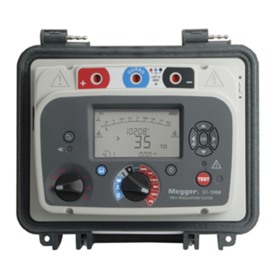
- Page 1 S1-568, S1-1068, S1-1568 5 kV, 10 kV & 15 kV High Performance DC Insulation Resistance Testers USER MANUAL...
-
Page 2: Safety Warnings
• If performing a two-wire test without guard using the S1-1068, insert the • Only 15 kV rated Megger test leads with plug inserts of 75 mm must blue safety plug. only be used on the S1-1568. Lead integrity can be verified by •... -
Page 3: Symbols Used On The Instrument
Equipment complies with current “C tick” requirements. Electronic equipment. The registration no is; WEE/HE0146QT. Users of Megger products in the UK may dispose of them at the end of their useful life by contacting B2B Compliance at Do not dispose of in the normal waste stream. -
Page 4: Table Of Contents
Calibration, Service and Spare Parts ........30 Recording temperature, humidity ........10 Returning product to Megger UK & USA service centres..30 Breakdown / burn mode – in IR & IR(t) test modes ..... 11 Approved Service Centres ............31 ... -
Page 5: General Description
15 kV. Resistance measurement capability is up to 15 TΩ for the 5 kV model, 35TΩ for the 10 kV and 50 TΩ for the 15 kV. Features S1-568 measures to 15TΩ and S1-1068, S1-1568 to 35 TΩ • 8 mA noise rejection plus 4 filter options ensure highest •... -
Page 6: Instrument Controls And Indicators
Instrument Controls and Indicators User lock voltage Delete records Timer Download via USB Save Filter 1. Positive (+) terminal Open records Alarm 2. GUARD terminal 3. Negative (-) terminal 4. 9-pin remote control socket Battery Breakdown mode 5. USB device interface 6. -
Page 7: Preparations For Use
Keep the original packaging for re-use. • Calibration Power lead and battery charging The S1-568 and S1-1068 are supplied with a calibration certificate. If the power lead supplied is not suitable for your AC • connection, do not use an adaptor. Always use a power UKAS accredited calibration certificates are available from Megger. -
Page 8: Operating Instructions
A range of test voltages for insulation resistance tests up to 5 kV (S1-568), 10 kV (S1-1068) and 15 kV (S1-1568) are available, including a user selectable voltage range which can be set between 40 V and 5000V or 10000 V or 15000 V depending on the model. -
Page 9: Breakdown Vs. Burn Mode
Breakdown vs. burn mode For further explanation see, “Running an Insulation Test” on page In breakdown mode insulation tests are automatically stopped when a fault causes the applied voltage to drop rapidly. Burn Reset Default Settings mode IR tests ignore breakdown and continue to test the insulation and are therefore destructive tests. -
Page 10: Instrument Control
The setting does not change even if the instrument is switched off. Initial setup It is important to setup the Real Time Clock (RTC) on S1-568 and Alarm setting S1-1068 to ensure that records saved in the instrument are A low resistance alarm can be set to sound when the resistance of time/date stamped correctly. -
Page 11: Breakdown / Burn Mode - In Ir & Ir(T) Test Modes
In the breakdown mode the breakdown icon will be indicated. The S1-568, S1-1068 and S1-1568 have been designed to handle high noise currents up to 8 mA. If currents above 8 mA are detected, In breakdown mode the test will automatically terminate on detection of a breakdown to prevent damage to the insulation. -
Page 12: Filter Button And Settings
the instrument will sound an urgent “warble” tone and be The save icon will appear momentarily to confirm the data is saved. If a full test curve is required the user must select logging by accompanied by the symbols pressing the save button before starting the test. In this case, data will be logged every 5 seconds for the duration of a resistance test. -
Page 13: Real-Time Output During Insulation Tests
Check the product CD provided with the instrument for a folder named, “Megger USB.” If this folder exists, use it when starting Recall results PowerDB for the first time to find the S1 driver, if not allow the Setting the central rotary switch to ‘open operating system to search the internet for the driver. -
Page 14: Bluetooth Interface Activation
Bluetooth interface ® activation ® The Bluetooth interface is set with the main rotary switch pointing to setting and the mode switch pointing at the remote control icon. ® To connect a PC or other intelligent device, enable the Bluetooth on the S1 and the PC. -
Page 15: Powerdb
Connecting to the S1-Series via Bluetooth is a straightforward process: resistance testers (IRTs), and many more. PowerDB Lite is bundled with the Megger’s MIT and S1-Series. The new S1-Series has remote control On the S1 instrument select the left hand... - Page 16 Expand the ‘Ports section in Device Manager. One serial port should Scroll down the PowerDB form until you see a table with cyan filled be allocated to ‘Megger Device (COMxx)’ where xx is the port headers. RIGHT CLICK once on one of the cyan coloured areas to activate number.
- Page 17 Import/Live Stream Control Application Start Importing Results – download results saved on the instrument If you are using an S1 and clicked Import from the remote control Sample remote control application: a timed insulation resistance test result application the Import/Live Stream Control Application will launch. shortly before completion of a 90 s test.
-
Page 18: Battery Indicator
Megger Instruments Limited, carefully pack in a A blinking full battery icon indicates that the battery is prevented suitable box and send the faulty instrument to the nearest Megger from charging due to the temperature being out of the allowable Approved Service Centre, if possible noting the error that was charge temperature range, 0 ºC to 40 ºC, or that the battery has... -
Page 19: Measurement Modes
Timed IR test Measurement Modes A timed test IR(t) will automatically terminate an ‘Spot’ IR test insulation test after a preset time. Default timer is The spot insulation resistance test (IR) is selected on the test set to 1 minute and is mode rotary switch. -
Page 20: Dielectric Discharge Test
DAR and PI insulation test voltages are selected on the central Dielectric Discharge Test rotary switch by simply aligning the switch opposite to the The Dielectric Discharge required insulation test voltage. Press and hold TEST to start a (DD) or reabsorption DAR/PI test. -
Page 21: Step Voltage Test
time If a standard 5 step test is required at the VL voltage, set timer DD = I /(V x C) 1min 1 to 0 sec. if a custom SV test has previously been setup. where I is the discharge current in mA one minute after 1min removal of the test voltage V in Volts and C is the capacitance in Rotary switch setting... -
Page 22: Remote Control Mode
The typical voltage ramp Remote control mode is activated with the test mode switch pointed (dV/dt) is at the remote control icon and the main rotary switch pointed at VL. 1 kV/min which is the default for S1 range. This All manual test modes can be setup, tests started and stopped value is user adjustable remotely. -
Page 23: Understanding Measurement Currents
Measurement Techniques Understanding Measurement Currents Insulation resistance is defined as the dc test voltage divided by In the case of dry insulation conductance current may be negligible, the total current flowing in an insulator. The total current has four and the leakage current may be low, in which case the absorption components;... -
Page 24: Insulation Measurements Above 100 Gω
Alternatively, screened leads are available as an optional accessory from Megger. When using a screened lead the screen is plugged into the Guard terminal, diverting any leakage currents. This considerably improves measurements made with a floating output, where the leads might touch each other or another object other than the test piece. -
Page 25: Guard Terminal, Screened Leads
measurements use just the + and – terminals. The instrument’s internal voltage generator drives the + terminal with respect to the – terminal, current being measured in the – terminal. GUARD terminal, screened leads For basic insulation tests and where there is little possibility of surface leakage affecting the measurement it is unnecessary to use the guard terminal, i.e. -
Page 26: Preventive Maintenance
A new battery is available as a Leads spare part from Megger. Genuine Megger battery packs must be Leads are silicone insulated and perform well in all weather used. Failure to use genuine parts may affect product safety conditions. -
Page 27: S1-1568 Battery Replacement Instructions
8. Replace with two genuine spare batteries ordered from Megger, ensuring correct orientation of the cable in the socket. 9. With both new batteries fitted, replace the battery support bracket and the two retaining screws. -
Page 28: Technical Specification
(0 °C to 30 °C) Insulation alarm: 100 kΩ to 10 GΩ Resistance range: S1-568 : 10 kΩ to 15 TΩ Capacitor chg bat pwr: < 2.5 s/µF to 5 kV, < 5 s/µF to 10 kV S1-1068: 10 kΩ to 35 TΩ... -
Page 29: Environmental Conditions
(V, I, R) at a rate of 1 Hz Capacitance range: With test voltage set above 500V Remote control: Remote control via USB cable only (requires S1-568 10 nF to 25 µF RC indicator dongle to be in position) S1-1068 10 nF to 25 µF S1-1568 10 nF to 50 µF... -
Page 30: Repair And Warranty
Returns Authorisation (RA) number on registration of the product on www.megger.com. You will need must first be obtained from one of the addresses shown above. -
Page 31: Approved Service Centres
Approved Service Centres A list of Approved Service Centres may be obtained from the UK address above, or by contacting Megger on ukrepairs@megger.com, and giving details of your location. Page 31... -
Page 32: Accessories, Equipment And Spares
Accessories, equipment and spares Part N umber Included accessories (S1-568, S1-1068) Part Number Screened HV test lead sets User guide CD 6220-835 3 m, 5 kV screened un-insulated small clips Power lead 15 m, 5 kV screened un-insulated small clips... -
Page 33: Sales Worldwide
F +41 62 768 20 33 F +91 22 26740465 This instrument is manufactured in the United Kingdom. The company reserves the right to change the specification or design without prior notice. Megger is a registered trademark Part No. S1568-S11068-S11568-ug-en_V02 0314 www.megger.com Page 33...
Need help?
Do you have a question about the S1-568 and is the answer not in the manual?
Questions and answers