
Related Manuals for Megger SPG 40


Summary of Contents for Megger SPG 40
- Page 1 Operating Manual Test and Fault Locating System SPG 40 Issue 9 (01/2017) – EN 128312675...
- Page 3 Megger shall not be liable for errors contained herein, nor for incidental or consequential damages from the furnishing of this information.
- Page 4 Connecting the HV-line to a faulty cable 6.2.5 Cordoning off open cable ends 6.2.6 Electrical connection of a time domain reflectometer 6.2.7 Connecting the SPG 40 to the mains Menus and Mode Operation 6.3.1 Switching On 6.3.2 Rotary Selector Remote control using Teleflex SX High Voltage control 6.5.1...
-
Page 5: Table Of Contents
7.3.1 Insulation Resistance Test 7.3.2 40 kV – DC Proof Test Operation mode Breakdown Recognition Fault Prelocating 7.5.1 Prelocating mode ARM (Arc Reflection Method) 7.5.2 Prelocating mode ICE (Impulse Current Equipment) 7.5.3 Prelocating mode Decay 7.5.4 Prelocating mode ICE-Plus (optional) Pinpointing Mode 7.6.1 Acoustic method... - Page 6 It is not allowed and the warranty is lost if other accessories than the original ones are used with the equipment. Repairs and service must only be done by Megger or authorised service departments of Megger. Megger recommends having the equipment serviced and checked once per year at a Megger service location.
- Page 7 Operation in traffic environment To ensure safety for operators and traffic, the country-specific regulations must be observed. Transport and operating position The device may only be operated and transported in an upright (standing) position! Using cardiac pacemaker Physical processes during operation of high voltage may endanger persons wearing a cardiac pacemaker when near these high voltage facilities.
- Page 8 Electrical Advice Dangers when operating with high voltage Special attention and safety-conscious behaviour is needed when operating high voltage facilities and especially non-stationary equipment. The regulations VDE 0104 about setting up and operation of electric test equipment, i.e. the corresponding EN 50191 as well as country-specific regulations and standards must be observed.
- Page 10 Burning 0 ... 8 kV ; 700 mA 0 ... 20 kV ; 100 mA Surge generator SPG 40-25 0 … 12.5 kV and 0 … 25 kV SPG 40-32 0 … 16 kV and 0 … 32 kV Surge generator - options: 0 ...
- Page 11 Scope of delivery and Options Scope of delivery Description Item Test and fault locating device SPG 40 Set of cables VL SPG-40 consisting of: AC mains connection NKG S2 Earthing connection cable EK 1 Auxiliary earth cable MK 54-B High voltage connection...
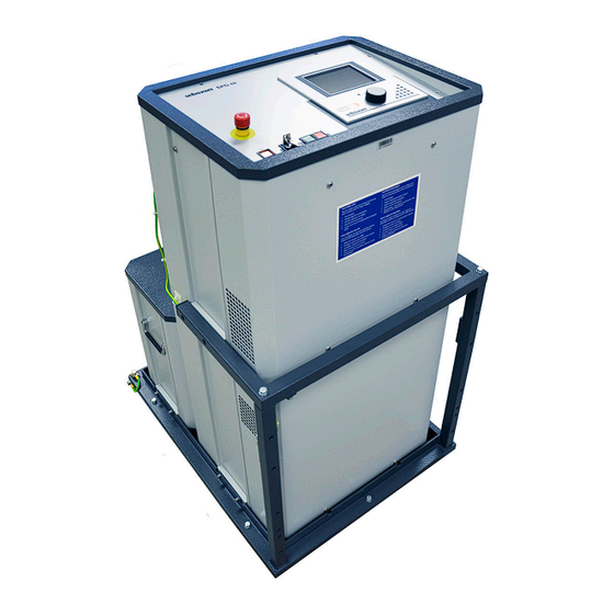
- Page 12 For safety reasons the high voltage setting must be activated with a separate hardware button. The operating panel is located in the top panel of the SPG 40 but it is optionally available as external control unit. man_spg40_en_09-4.doc...
- Page 13 Combined fault locating system Surgeflex 40 (SFX 40) Combined with a reflectometer of type Teleflex SX or T3060, the SPG 40 is enhanced by the most common HV pre-locating methods and so upgraded to a fully fledged fault locating system (SFX 40).
- Page 14 Because the SPG 40 generates a hazardous voltage of more than 1 kV it must be operated by trained specialists only. The following safety measures should...
- Page 15 Also for safety for the operator, the auxiliary earth connection [23] must be connected to a ground rod as close as possible to the SPG 40. The FU-safety circuit of the SPG 40 will immediately shut the unit off and ground the cable...
- Page 16 Test sites in general have to be equipped with an emergency OFF button. The SPG 40 has a red emergency OFF button on the face plate (see page 17, Fig. 2). An external safety device with an emergency stop switch is optionally available (820003206).
- Page 17 Operating Connections and controls white green Fig. 2: Controls Element Function emergency OFF button push-button – white on/off switch press: activates system controls lit: device is switched on key switch push-button – green: HV-ON key lit: HV readiness for switching on (high voltage can be switched on) press: Switches the high voltage on;...
- Page 18 Control connection to external control panel (optional) 10. CAN bus connection to Teleflex SX / T 30-E control panel 11. Control line to separated control elements SPG 40-1 (since 2015): Teleflex SX-M, system control panel of a test van or external safety...
- Page 19 Electrical Connection During electrical connection, please observe the safety precations in section 1.2. 6.2.1 Connection Sequence The electrical connection must be carried out in the sequence shown in the figure. Connection to the mains occurs last! 230 V (optional 110 V), 50/60 Hz (Sinus) Connection of the earthing cable Connection of the FU cable (auxiliary earth)
- Page 20 6.2.2 Safety Earth The SPG 40 has to be earthed before use. To do so connect the protective earth connection [10] to a good safety earth (e.g. station earth, etc.) using the earth lead EK1 supplied. Note that the earthing clamp should only be attached to clean metallic points of contact.
- Page 21 These currents could develop due to the discharge characteristic of the surge capacitor when the flash-over in the cable occurs at a very short distance of the point of connection. HV-connecting cable (shielded) SPG 40 power cable i.e. with shield FΩ < 6Ω OE: operating earth...
- Page 22 PEN-conductor using an earth bridge xa.x (Fig. 5). Without this bridge the SPG 40 could not be turned on due to the F-Ohm protection (see chapter 5.2). The center conductor of the HV connecting cable is connected to the faulty phase.
- Page 23 Now the SPG 40 can be connected to the mains. Make sure that the mains voltage is the same as the supply voltage of the SPG 40 (230 V AC or 115 V AC, according to the type label of the instrument).
- Page 24 The moment that the AC mains connector is plugged into a power supply, the SPG 40 is in stand-by mode – no button is lit yet. Press the white push button [2] to start the SPG 40.
- Page 25 ICE Plus locating method) can be controlled directly from the Teleflex SX. The SPG 40 display is darkened in this mode and the encoder [6] has no function. The remote control mode on the Teleflex SX must be activated before measurement is begun.
- Page 26 5 seconds, the “HV – ON” field must be re-activated). Now the SPG 40 is in "HV enabled" mode: the red button [5] lights up as the light in the green button [4] goes off and HV is activated. Now the selected mode is active.
- Page 27 Functions Setup- Menu SPG 40 10:32:16 Day: Hour: Month: Minute: Year: 2005 Second: return English Date/Time Contrast Language active active return F-Ohm Fig. 8: Setup menu...
- Page 28 Safety Menu Safety Circuit FU – step voltage FOHM loop resistance error Emergency Off Switch External Emergency Off Switch Key switch Over temperature System HV connector Earth connection Rear door return clear Fig. 9: Menu safety circuit The Safety Menu will appear automatically in case of any error. To return to the normal operating mode the error must be eliminated and confirmed with “clear”.
-
Page 29: Insulation Resistance Test
Testing Mode The Testing mode offers the possibility of an insulation resistance test up to 5 kV or a DC proof test up to 40 kV. 7.3.1 Insulation Resistance Test Insulation Resistance 12 MΩ 5000 V Output Voltage Insulation Resistance 5000 V return HV-ON... -
Page 30: Kv - Dc Proof Test
Turn off with the field “HV-OFF” or by pushing the red button [5]. If a breakdown occurs during the test with the timer turned on, the SPG 40 will shut off and ground the cable over a discharge resistor and the breakdown voltage will be displayed (identical to 'Breakdown recognition'-mode). -
Page 31: Operation Mode Breakdown Recognition
After a breakdown occurred, the breakdown voltage is shown. This mode does not have a timer function as in testing, but the SPG 40 will automatically turn off the high voltage after the breakdown has occurred. -
Page 32: Fault Prelocating
Connect the signal connection of the TDR to the connection for ARM [14] and the TDR trigger connection to the ARM Trigger [13]. Releasing a "Single Shot" will discharge the surge capacitor of the SPG 40 via an inductive filter (choke) into the faulty cable. - Page 33 TDR adjustments: 6 a. Adjust settings of the connected TDR and acquire reference trace with the SPG 40 still set at 0 kV. Also when retrieving a new reference trace at a later time, the voltage should again be set to 0 kV to avoid interference with the power supply.
-
Page 34: Prelocating Mode Ice (Impulse Current Equipment)
7.5.2 Prelocating mode ICE (Impulse Current Equipment) The ICE method (also called "surge pulse" method) requires a TDR (Time Domain Reflectometer) to be connected to the connection I [21]. The TDR must be set to ICE-mode. Wear Ear Protection Surge operation can cause high and sudden noise levels. It is strongly recommended to wear hearing protection during surge operation. -
Page 35: Prelocating Mode Decay
Push green button (within 5 sec.) TDR adjustments: 6 a. Adjust settings of the connected TDR. 6 b. Arm trigger of the TDR. Select max. voltage. Release single pulse: By activating the field “single pulses” only one single pulse is released into the faulty cable. -
Page 36: Prelocating Mode Ice-Plus (Optional)
Turn off with the field “HV-OFF” or by pushing the red button [5]. If a breakdown occurs during the test with the timer turned on, the SPG 40 will shut off and ground the cable over a discharge resistor and the breakdown voltage will be displayed (identical to 'Breakdown recognition'-mode). - Page 37 Select operating mode ‘Prelocation’ in main menu. Select operating mode ‘ICE-Plus’ in prelocation menu. Activate field "cable data". Under “cableinput” (at the top) select one of the following: “accept old cable data” (no changes, continue with step 10) “modify cable data” (change previous data) “set new cable data”...
- Page 38 10. Confirm the cable data input by pressing “next”. 11. Another menu opens, as shown in the figure below. ICE-Plus 2000 V Output Voltage 2000 V 460 m single puls max. faultdistance return HV-ON HV-OFF Fig. 17: Menu ICE-Plus 12. Activate field “HV-ON”. 13.
-
Page 39: Pinpointing Mode
Pinpointing Mode There are two kinds of pinpoint locating to choose from: The sound field method with a surge wave generator. The step voltage method with a DC output voltage 0 … 5 kV, which can be pulsed. 7.6.1 Acoustic method Wear Ear Protection... - Page 40 Operating : Select ‘Pinpointing’ in main menu. Activate field ‘Acoustic’. After selecting the desired voltage range the above menu appears (Fig. 18: Menu ICE (impulse current / surge pulse method)). Note: The impulse energy is 1000 J at full voltage in the respective selected range.
-
Page 41: Step Voltage Method
7.6.2 Step Voltage Method Pinpointing - Step voltage 5 kV 400 V 70 % Output Voltage Output Current 1000mA 2500 V 70 % Sequence max. voltage max. current return HV-ON HV-OFF push green button enabling HV source, please wait ... set voltage Fig. -
Page 42: Burn Mode
Burn Mode Burning 450 V 30 % output voltage current display 1000mA 2500 V 8 kV 30 % Burning max. voltage max. current return HV - ON HV-OFF push green button enabling HV source, please wait ... set voltage Fig. 20: Menu Burning Operating : Select ‘burning’... -
Page 43: Shutting Down The Fault Location System
Shutting Down the Fault Location System After the measurements on a cable have been completed, the system can be switched off by pressing the ON/OFF button. When disconnecting the test system, proceed in reverse sequence to the manner in which the connection (see section 6.2) was made. The following safety instructions must be strictly adhered to. -
Page 44: Care And Maintenance
Cleaning Cleaning a Megger product may only be done with the instrument turned off High Voltage equipment must also be discharged and short-circuited. Under these conditions a slightly wet towel may be used to whip off the equipment. -
Page 45: Service And Service Contacts
Service and Service Contacts Megger products are undergoing a tight quality monitoring. If you should experience any problems or if you would like to inquire about any other comprehensive Megger service, please contact us. The current services of Megger are listed on the internet under www.megger .com... - Page 46 man_spg40_en_09-4.doc...
Need help?
Do you have a question about the SPG 40 and is the answer not in the manual?
Questions and answers