Table of Contents
Advertisement
Available languages
Available languages
Quick Links
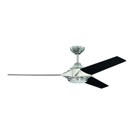
Echelon
Installation Guide
For Model:
ECH54
WARNING
DC Motor will not operate
until blades are installed
E192641
net weight of fan: 17.86 lb (8.10 kg)
READ THESE INSTRUCTIONS AND
SAVE THEM FOR FUTURE USE
Table of Contents:
Safety Tips. pg. 2
Unpacking Your Fan. pg. 2
Parts Inventory. pg. 3
Installation Preparation. pg. 4
Hanging Bracket Installation. pg. 4
Fan Assembly. pgs. 5 - 6
Wiring. pg. 7
Canopy Assembly. pg. 8
Blade Assembly. pg. 8
Remote/Wall Control Operation. pg. 12
Testing Your Fan. pg. 12
Troubleshooting. pg. 13
Warranty. pg. 13
Parts Replacement. pg. 13
page 1
PRINTED IN CHINA
Advertisement
Chapters
Table of Contents

Related Manuals for Craftmade Echelon


Summary of Contents for Craftmade Echelon
-
Page 1: Table Of Contents
READ THESE INSTRUCTIONS AND SAVE THEM FOR FUTURE USE Echelon Installation Guide For Model: ECH54 Table of Contents: Safety Tips. pg. 2 Unpacking Your Fan. pg. 2 Parts Inventory. pg. 3 Installation Preparation. pg. 4 Hanging Bracket Installation. pg. 4 Fan Assembly. -
Page 2: Safety Tips
SAFETY TIPS. WARNING: To reduce the risk of electrical shock, turn off the electricity to the fan at the main fuse box or circuit panel before you begin the fan installation or before servicing the fan or installing accessories. READ ALL INSTRUCTIONS AND SAFETY INFORMATION CAREFULLY BEFORE INSTALLING YOUR FAN AND SAVE THESE INSTRUCTIONS. -
Page 3: Parts Inventory
1. Unpacking Your Fan. Carefully open the packaging. Remove items from Styrofoam inserts. Remove motor housing and place on carpet or Styrofoam to avoid damage to finish. Do not discard fan carton or Styrofoam inserts should this fan need to be returned for repairs. Check against parts inventory that all parts have been included. -
Page 4: Installation Preparation
3. Installation Preparation. blade edge To prevent personal injury and damage, ensure inches 7 feet that the hanging location allows the blades a (2.13 m) (76 cm) clearance of 7 feet (2.13m) from the floor and 30in. (76cm) from any wall or obstruction. This fan is suitable for room sizes up to 400 square 12ft. -
Page 5: Fan Assembly. Pgs
5. Fan Assembly. stop pin set screw Remove hanging ball from downrod provided by loosening set screw on hanging ball. Lower hanging ball and remove stop pin and then slide hanging hanging ball ball off of the downrod. [Refer to diagram 1.] Loosen yoke set screws and nuts at top of motor diagram 1 housing. - Page 6 5. Fan Assembly. (cont.) With the hanging bracket secured to the outlet wood ceiling joist box and able to support the fan, you are now ready to hang your fan. Grab the fan firmly with safety cable loop two hands. Slide downrod through opening in hanging bracket and let hanging ball rest on the hanging bracket.
-
Page 7: Wiring
6. Wiring. WARNING: Turn off circuit breakers to current fixture white supply wire from breaker panel and be sure switch is turned to the ground OFF position. (green or bare) black supply wire CAUTION: Be sure outlet box is properly grounded and that a ground wire (GREEN or Bare) is present. -
Page 8: Canopy Assembly
7. Canopy Assembly. hanging Locate 2 screws on underside of hanging bracket bracket and remove screw closest to the open end of the hanging bracket. Partially loosen the other screw. Lift canopy to hanging bracket. Place rounded part of slotted hole in canopy screw over loosened screw in hanging bracket and canopy... -
Page 9: Light Kit Assembly (Optional)
motor 9. Light Kit Assembly (Optional). housing Remove 1 screw from motor plate on underside of motor housing and partially loosen the other 2 screws. Align slotted holes in center of fitter plate with loosened screws in motor plate, allowing molex connections from motor housing to come through hole in middle of fitter plate. -
Page 10: Handheld Remote Control Assembly
10. Handheld Remote Control Assembly. IN ORDER TO USE THE HANDHELD REMOTE remote CONTROL, PLEASE CONTINUE WITH SECTION 10 for control remote control assembly instructions. If you have cover already installed the wall control but do not wish to use the handheld remote control, please proceed to Section 11. -
Page 11: Automated Learning Process./Activating Code
11. Automated Learning Process./Activating Code. CAUTION: The wall and/or handheld remote control wall control can be programmed to multiple receivers or fans. If this is not desired, turn wall switch off to any other programmable receiver or fan. Restore electrical power and then, if using wall control, set slider switch on wall control to the ON position. -
Page 12: Remote/Wall Control Operation
12. Remote/Wall Control Operation. handheld wall control remote control IMPORTANT: Handheld remote control and wall III IV control must be SYNCHRONIZED with fan in order to properly function. Fan SPEED control buttons--1: Use to control the ceiling fan speed 1-6 Fan OFF button--2: Use to turn the fan off REVERSE function button--3:... -
Page 13: Troubleshooting
Service at 1-800-486-4892 to arrange for return of fan. properly. Return fan, shipping prepaid, to Craftmade. We will repair 3. Check to be sure fan is wired properly. or ship you a replacement fan, and we will pay the return 4. - Page 14 LEER ESTAS INSTRUCCIONES Y GUARDARLAS PARA UTILIZACION FUTURA Echelon Guía de instalación Para modelo: ECH54 Índice de materias: Sugerencias de seguridad. Pág. 2 Desempaquetado del ventilador. Pág. 3 Inventario de piezas. Pág. 3 Preparación para la instalación. Pág. 4 Instalación del soporte de montaje. Pág. 4 Ensamblaje del ventilador.
-
Page 15: Sugerencias De Seguridad. Pág
SUGERENCIAS DE SEGURIDAD. ADVERTENCIA: para evitar la posibilidad de una descarga eléctrica, desconectar la corriente en la caja de fusibles principal o el interruptor protector antes de iniciar la instalación del ventilador o antes de repararlo o instalar accesorios. LEER TODAS LAS INSTRUCCIONES E INFORMACION DE SEGURIDAD CUIDADOSAMENTE ANTES DE INSTALAR SU VENTILADOR Y GUARDAR ESTAS INSTRUCCIONES. -
Page 16: Desempaquetado Del Ventilador. Pág
1. Desempaquetado del ventilador. Abrir el empaque cuidadosamente. Sacar los artículos del embalaje. Sacar el motor y ponerlo en una alfombra o en el embalaje para evitar rayar el acabado. Guardar la caja de cartón o el empaquetamiento original en caso de que tenga que mandar el ventilador para alguna reparación. -
Page 17: Preparación Para La Instalación. Pág
3. Preparación para la instalación. Para prevenir daño corporal y otros daños, estar seguro borde del aspa de que el lugar en donde va a colgar el ventilador le 76 cm permite un espacio libre de 2,13 m (7 pies) entre las puntas de las aspas y el piso y 76 cm (30 pulg.) entre las 2,13 m pulg.) -
Page 18: Ensamblaje Del Ventilador. Págs
5. Ensamblaje del ventilador. perno de tope tornillo Quitar la bola que sirve para colgar del tubo provisto de fijación aflojando el tornillo de fijación de la bola que sirve para colgar. Bajar la bola que sirve para colgar y sacar el perno bola que de tope y luego quitar la bola que sirve para colgar sirve para... - Page 19 5. Ensamblaje del ventilador. (cont.) Ya que esté sujeto el soporte de montaje a la caja viga de madera de salida y capaz de apoyar el ventilador, usted bucle del cable está listo para colgar el ventilador. Agarrar el de seguridad ventilador firmemente con las dos manos.
-
Page 20: Instalación Eléctrica. Pág
6. Instalación eléctrica. alambre conductor blanco toma de tierra ADVERTENCIA: apagar los cortacircuitos en el panel de (verde o pelada) alambre conductor negro electricidad que suplen corriente a la caja de salida y asegurarse de que el interruptor de luz esté APAGADO. PRECAUCION: asegurarse de que la caja de salida esté... -
Page 21: Colocación De La Cubierta Decorativa. Pág
7. Colocación de la cubierta decorativa. Localizar los 2 tornillos en la parte inferior del soporte de montaje y quitar el tornillo que está soporte de localizado más cerca del extremo abierto del montaje soporte de montaje. Aflojar parcialmente el otro tornillo. - Page 22 bastidor 9. Instalación del juego de luz (opcional). del motor Quitar 1 tornillo de la placa del motor en el lado inferior del bastidor del motor y parcialmente aflojar los otros 2 tornillos. Alinear los agujeros con ranura en el centro de la placa de conexión con los tornillos aflojados en la placa del motor, dejando que las conexiones tipo "molex"...
-
Page 23: Ensamblaje Del Control Remoto De Mano. Pág
10. Ensamblaje del control remoto de mano. PARA PODER UTILIZAR EL CONTROL REMOTO DE MANO, cubierta del FAVOR DE SEGUIR CON LA SECCION 10 para armar el control remoto control remoto. Si ya se instaló el control de pared pero no desea utilizar el control remoto de mano, favor de pasar a la sección 11. - Page 24 11. Proceso de aprendizaje automático./Activar el código. PRECAUCION: se puede programar el control de pared/ control remoto de mano para usar con varios receptores control de pared o ventiladores. Si no desea hacer esto, apagar el interruptor de cualquier otro receptor o ventilador programable.
- Page 25 12. Funcionamiento del control remoto/de pared. control remoto de mano control de pared IMPORTANTE: hay que SINCRONIZAR el III IV control remoto de mano y el control de pared con el ventilador para que funcionen correctamente. Botones de VELOCIDAD del ventilador--1: usar para controlar la velocidad del ventilador de 1- 6 Botón de APAGADO--2: usar para apagar el ventilador...
- Page 26 Craftmade. Nosotros repararemos el motor al comprador o le enviaremos uno de reemplazo Problema: el juego de luz (opcional) no se ilumina. y Craftmade pagará los gastos de envío de regreso. Soluciones: GARANTÍA LIMITADA DE 6 AÑOS hasta DE POR VIDA: 1.
Need help?
Do you have a question about the Echelon and is the answer not in the manual?
Questions and answers