Table of Contents
Advertisement
Advertisement
Chapters
Table of Contents

Related Manuals for Beckhoff CX51x0


Summary of Contents for Beckhoff CX51x0
- Page 1 Manual | EN CX51x0 Embedded-PC 11/8/2021 | Version: 2.8...
-
Page 3: Table Of Contents
Staff qualification .......................... 11 Safety instructions ........................... 11 Notes on information security ...................... 12 3 Transport and storage.......................... 13 4 Product overview............................. 14 Configuration of the CX51x0 Embedded PC ................... 15 Name plate ............................ 16 Types ............................... 16 Architecture overview ........................ 19 5 Interface description .......................... 21 USB (X100, X101, X102, X103) ...................... 21 Ethernet RJ45 (X000, X001) ...................... 22... - Page 4 7.2.2 Enabling jumbo frames .................... 44 7.2.3 Set NIC Teaming ...................... 45 7.2.4 Restoring the Beckhoff real-time driver................ 47 Windows 10 IoT Enterprise LTSB .................... 48 7.3.1 Identification of the Ethernet interfaces (X000, X001) ............. 48 7.3.2 Enabling jumbo frames .................... 49 7.3.3...
- Page 5 Table of contents List of figures ............................ 93 CX51x0 Version: 2.8...
- Page 6 Table of contents Version: 2.8 CX51x0...
-
Page 7: Notes On The Documentation
EP1590927, EP1789857, EP1456722, EP2137893, DE102015105702 with corresponding applications or registrations in various other countries. ® EtherCAT is a registered trademark and patented technology, licensed by Beckhoff Automation GmbH, Germany Copyright © Beckhoff Automation GmbH & Co. KG, Germany. The reproduction, distribution and utilization of this document as well as the communication of its contents to others without express authorization are prohibited. -
Page 8: Representation And Structure Of Warnings
There is a potential hazard to the environment and equipment. Notes showing further information or tips: This notice provides important information that will be of assistance in dealing with the product or software. There is no immediate danger to product, people or environment. Version: 2.8 CX51x0... -
Page 9: Documentation Issue Status
Notes on operation in potentially explosive atmospheres added. Technical data, graphic card specifications adapted. Chapter on serial interfaces N030/N031 added. Chapter Beckhoff Device Manager revised Chapter "RS232 (N030)" adapted. Chapter "Power supply" adapted. Chapter Technical data adapted. Chapter “Types” and “Device Manager” revised. -
Page 10: For Your Safety
Beckhoff Automation GmbH & Co. In addition, the following actions are excluded from the liability of Beckhoff Automation GmbH & Co. KG: • Failure to comply with this documentation. -
Page 11: Staff Qualification
For your safety Staff qualification All operations involving Beckhoff software and hardware may only be carried out by qualified personnel with knowledge of control and automation engineering. The qualified personnel must have knowledge of the administration of the Industrial PC and the associated network. -
Page 12: Notes On Information Security
IPC Security Guideline Notes on information security The products of Beckhoff Automation GmbH & Co. KG (Beckhoff), insofar as they can be accessed online, are equipped with security functions that support the secure operation of plants, systems, machines and networks. Despite the security functions, the creation, implementation and constant updating of a holistic security concept for the operation are necessary to protect the respective plant, system, machine and networks against cyber threats. -
Page 13: Transport And Storage
• Remove the battery from the Embedded PC if storage temperatures exceed 60 °C. The battery should be stored separate from the Embedded PC in a dry environment at a temperature between 0 °C and 30 °C. The preset date and time are lost if the battery is removed. CX51x0 Version: 2.8... -
Page 14: Product Overview
Product overview The CX5100 product family comprises three Embedded PCs, which differ in terms of processor type, RAM and housing size. The CX51x0 Embedded PC is a full-fledged PC with the following basic configuration: • CFast card slot, • MicroSD card slot, •... -
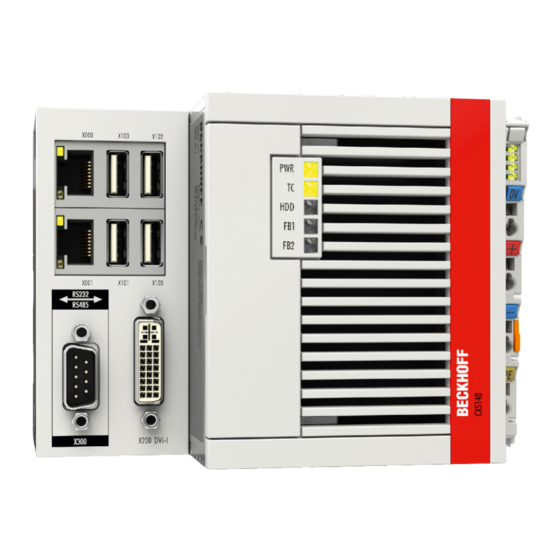
Page 15: Configuration Of The Cx51X0 Embedded Pc
Product overview Configuration of the CX51x0 Embedded PC Fig. 1: Example: CX5140 Embedded PC. Table 3: Legend for the configuration. Component Description Optional interface (X300). Space for interfaces such as RS232, EtherCAT, CANopen or others. The optional interface must be ordered ex factory and cannot be retrofitted retrospectively. -
Page 16: Name Plate
License sticker for operating system (optional). Types The CX51x0 Embedded PC can be ordered with different software options. Use this overview in conjunction with the information on the name plate to ascertain the operating system and the TwinCAT version of the Embedded PC. -
Page 17: Table 5: Order Details, Cx51X0 With Windows Embedded Compact 7
Runtime CX51x0-0100 CX51x0-0110 CX51x0-0111 CX51x0-0112 CX51x0-0113 CX51x0-0115 Only one CPU core is supported with Microsoft Windows Embedded Compact 7. Table 6: Order details, CX51x0 with Windows Embedded Standard 7 P. Module Windows Windows TwinCAT 2 TwinCAT 2 TwinCAT 2 TwinCAT 3... -
Page 18: Table 7 Order Details, Cx51X0 With Windows 10 Iot Enterprise
CX51x0-0170 CX51x0-0175 A CX51x0 Embedded PC with Windows Embedded Compact 7 requires a CFast card with a capacity of at least 20 GB. A CFast card with a capacity of at least 40 GB is required for Microsoft Windows Embedded Standard 7 P and Microsoft Windows 10 IoT Enterprise. -
Page 19: Architecture Overview
Product overview Architecture overview The Embedded PCs of the CX51x0 family all have the same architecture. This is described below. The CX51x0 Embedded PCs are based on the Intel Atom microarchitecture, which was developed by Intel. The following CPUs are used: ®... - Page 20 A VGA monitor can be connected to the DVI-I interface with an adapter. ® Intel i210 Gigabit Ethernet controllers are used as network controllers. There are two independent Ethernet interfaces. Both LAN interfaces are gigabit-capable. Version: 2.8 CX51x0...
-
Page 21: Interface Description
The USB interfaces are type A and comply with the USB 2.0 specification. Table 8: USB interfaces (X100, X101, X102, X103), pin assignment. Connection Typical assignment VBUS White Green Black Shell Shield Drain Wire Note the power consumption of the individual devices. Each interface is limited to 500 mA. CX51x0 Version: 2.8... -
Page 22: Ethernet Rj45 (X000, X001)
100 Mbit, the LED lights up green. The LED lights up red if the speed is 1000 Mbit (gigabit). Table 9: Ethernet interface X000 and X001, pin assignment. Signal Description T2 + Pair 2 T2 - T3 + Pair 3 T1 + Pair 1 T1 - T3 - Pair 3 T4 + Pair 4 T4 - Version: 2.8 CX51x0... -
Page 23: Dvi-I (X200)
The DVI-I interface (X200) transfers digital data and is suitable for connection to digital or analog monitors. The resolution at the display or the Beckhoff Control Panel depends on the distance from the display device. The maximum distance is 5 m. Beckhoff offers various Panels with an integrated “DVI extension”. These make a cable length of up to 50 meters possible. -
Page 24: Optional Interfaces
N010 interface (DVI-D interface) is used, the first DVI-I interface can be operated either in VGA mode or in DVI mode. The resolution at the display or the Beckhoff Control Panel depends on the distance from the display device. The maximum distance is 5 m. Beckhoff offers various Panels with an integrated “DVI extension”. -
Page 25: Displayport (N011)
AUX channel+ Ground AUX channel- Hot-plug detection Power supply: Ground Power supply: 3.3 V / 500 mA Table 16: DisplayPort X300, resolution at the monitor. Interface Resolution in pixels DisplayPort max. 2560x1600@60Hz DisplayPort with adapter, DisplayPort to DVI-D max. 1600x1200@60Hz CX51x0 Version: 2.8... -
Page 26: Audio Interface (N020)
Table 17: Line In /Line Out jack plugs, pin assignment. Signal Description Left channel Right channel Ground Ground The only existing channel is transferred via the tip, the remainder of the sleeve is used for earthing. Fig. 11: Mic In X301 jack plug. Version: 2.8 CX51x0... -
Page 27: Rs232 (N030)
Windows. The following API and IOCTLs are not supported: • SetupComm • SetCommBreak • ClearCommBreak • EscapeCommFunction (no support for parameters SETBREAK and CLR-BREAK) • IOCTL_SERIAL_XOFF_COUNTER • IOCTL_SERIAL_LSRMST_INSERT • IOCTL_SERIAL_SET_BREAK_ON • IOCTL_SERIAL_SET_BREAK_OFF CX51x0 Version: 2.8... -
Page 28: Rs422/Rs485 (N031)
• N031-0002 RS485 without echo, stub (without termination). • N031-0003 RS485 with echo, stub (without termination). • N031-0004 RS422 full duplex end point (terminated). An RS485 interface cannot be configured retrospectively and must always be ordered ex factory as required. Version: 2.8 CX51x0... -
Page 29: Ethercat Slave (B110)
Receive + connected reserved RD - Receive - connected reserved For the optional EtherCAT slave interface (B110), documentation with further information is available for download from the Beckhoff website: https://www.beckhoff.de/german/download/epc.htm?id=71003127100362 Document name CXxxx0-B110 optional interface EtherCAT slave. CX51x0 Version: 2.8... -
Page 30: Profibus (X310)
PROFIBUS line D sub B red Pin 3 A green Pin 8 For the optional PROFIBUS interface (x310), documentation with further information is available for download from the Beckhoff website: https://www.beckhoff.de/german/download/epc.htm?id=71003127100362 Document name CXxxx0-x310 optional Profibus interface. Version: 2.8 CX51x0... -
Page 31: Canopen (X510)
CAN Ground (internally connected to pin 3) CAN high (CAN+) not used not used For the optional CANopen interface (x510), documentation with further information is available for download from the Beckhoff website: https://www.beckhoff.de/german/download/epc.htm?id=71003127100362 Document name CXxxx0-x510 optional CANopen interface. CX51x0... -
Page 32: Profinet Rt (X930)
5.4.9 PROFINET RT (x930) Fig. 17: PROFINET RT interface X300. Table 25: PROFINET RT interface, pin assignment. Signal Description TD + Transmit + TD - Transmit - RD + Receive + connected reserved RD - Receive - connected reserved Version: 2.8 CX51x0... -
Page 33: Commissioning
In addition, a minimum clearance of 30 mm above and below the Embedded PCs required, in order to ensure adequate ventilation. Fig. 18: CX51x0 Embedded PC, permitted installation position. If vibrations and impact occurs in the same direction as the mounting rail, the Embedded PC must be secured with an additional bracket, in order to prevent it slipping. -
Page 34: Fig. 19 Cx51X0 Embedded Pc, Invalid Installation Positions
Commissioning Incorrect installation positions Fig. 19: CX51x0 Embedded PC, invalid installation positions. Version: 2.8 CX51x0... -
Page 35: Attaching On Mounting Rail
Embedded PC has latched. 3. Then lock the latches again. ð You have installed the Embedded PC successfully. Double-check the correct installation and latching of the Embedded PC on the mounting rail. CX51x0 Version: 2.8... -
Page 36: Microsd Card Installation And Removal
MicroSD cards from other manufacturer may fail, resulting in data loss. Only use industrial MicroSD cards provided by Beckhoff. The MicroSD card slot is intended for a MicroSD card. Data and further programs can be stored here, or Windows Embedded Compact 7 can be installed instead. -
Page 37: Cfast Card Installation And Removal
A CFast card is a non-volatile memory. Data to be retained in the event of a power failure should be saved on the CFast card. The CFast cards supplied by Beckhoff are industrial cards with an increased number of write cycles and an extended temperature range (+85 °C). -
Page 38: Installing Passive Ethercat Terminals
The following diagram shows the permissible installation of a passive EtherCAT Terminal. The passive EtherCAT Terminal was not directly attached to the power supply unit. Fig. 21: Passive EtherCAT Terminals, permissible installation. The following diagram shows the invalid installation of a passive EtherCAT Terminal. Fig. 22: Passive EtherCAT Terminals, invalid installation. Version: 2.8 CX51x0... -
Page 39: Connecting The Power Supply
• When dimensioning the fuse for the system voltage (Us), observe the max. power consumption of the Embedded PC (see: Technical Data [} 85]). • Protect power contacts (Up) with a fuse of max. 10 A (slow blow). CX51x0 Version: 2.8... -
Page 40: Table 27 Required Wire Cross-Sections And Strip Lengths
Fig. 23: UL label for CX51x0 Embedded PC. The CX51x0 Embedded PCs can thus be used in areas in which special UL requirements have to be met. These requirements apply to the system voltage (Us) and to the power contacts (Up). Application areas without special UL requirements are not affected by UL regulations. -
Page 41: Switching On
1. Stop all running programs properly, e.g. the control software on the Embedded PC. 2. Shut down the operating system. 3. Do not switch off the external power supply until all other tasks have been completed, in order to switch off the Embedded PC. CX51x0 Version: 2.8... -
Page 42: Configuration
Configuration Windows Embedded Compact 7 7.1.1 Setting up the audio interface (N020) Under Windows Embedded Compact 7, the Beckhoff CX configuration tool can be used for the audio settings. Requirements: • Embedded PC with audio interface. • Windows Embedded Compact 7. -
Page 43: Windows Embedded Standard 7 P
Identification of the Ethernet interfaces (X000, X001) Network and Sharing Center In the Network and Sharing Center the Ethernet interfaces (X000, X001) of the CX51x0 Embedded PC are identified as follows as standard: • Local Area Connection corresponds to Ethernet interface X000. -
Page 44: Enabling Jumbo Frames
Requirements: • The original Intel® driver can be downloaded from https://downloadcenter.intel.com. • Install the original Intel® driver. Note that this will delete the real-time capable driver from Beckhoff. • Check whether the peripheral devices support jumbo frames. Jumbo frames are activated as follows: 1. -
Page 45: Set Nic Teaming
• The original Intel® driver can be downloaded from https://downloadcenter.intel.com. • Install the original Intel® driver for the Network Interface Card. Note that this will delete the real-time capable driver from Beckhoff. NIC Teaming is set as follows: 1. Under Start > Control Panel > Hardware and Sound click on Device Manager. - Page 46 5. Under Select a team type select the option Adapter Fault Tolerance 6. Click on Next to complete the installation. ð You have successful set NIC Teaming for your Ethernet interfaces. Further settings can be specified or changed under the Settings tab. Version: 2.8 CX51x0...
-
Page 47: Restoring The Beckhoff Real-Time Driver
The installation dialog appears and shows the compatible Ethernet interfaces under Compatible devices. 2. Select the Ethernet interfaces for which you wish to restore the Beckhoff real-time driver and click on Install. ð The Beckhoff real-time driver is installed. The Ethernet interfaces with installed Beckhoff real-time driver are shown under Installed and ready to use devices (real-time capable). -
Page 48: Windows 10 Iot Enterprise Ltsb
Identification of the Ethernet interfaces (X000, X001) Network and Sharing Center In the Network and Sharing Center the Ethernet interfaces (X000, X001) of the CX51x0 Embedded PC are identified as follows as standard: • Ethernet corresponds to the Ethernet interface X000. -
Page 49: Enabling Jumbo Frames
Requirements: • The original Intel® driver can be downloaded from https://downloadcenter.intel.com. • Install the original Intel® driver. Note that this will delete the real-time capable driver from Beckhoff. • Check whether the peripheral devices support jumbo frames. Jumbo frames are activated as follows: 1. -
Page 50: Set Nic Teaming
• The original Intel® driver can be downloaded from https://downloadcenter.intel.com. • Install the original Intel® driver for the Network Interface Card. Note that this will delete the real-time capable driver from Beckhoff. NIC Teaming is set as follows: 1. Under Start > Control Panel > Hardware and Sound click on Device Manager. - Page 51 5. Under Select a team type select the option Adapter Fault Tolerance 6. Click on Next to complete the installation. ð You have successful set NIC Teaming for your Ethernet interfaces. Further settings can be specified or changed under the Settings tab. CX51x0 Version: 2.8...
-
Page 52: Restoring The Beckhoff Real-Time Driver
The installation dialog appears and shows the compatible Ethernet interfaces under Compatible devices. 2. Select the Ethernet interfaces for which you wish to restore the Beckhoff real-time driver and click on Install. ð The Beckhoff real-time driver is installed. The Ethernet interfaces with installed Beckhoff real-time driver are shown under Installed and ready to use devices (real-time capable). -
Page 53: Table 28 System Requirements For The Operation Of The N030 And N031 Serial Interfaces
TwinCAT version. Observe the system requirements in order to be able to operate the serial interfaces with Windows 10: Table 28: System requirements for the operation of the N030 and N031 serial interfaces. Order designation BIOS version Image version TwinCAT Version CX51x0-N030 0.79 CX1800-0501-0011v2.0 2.11.2302 CX51x0-N031 CX1800-0511-1011v2.0 3.1.4022.27 For driver-related reasons there are two operation modes. - Page 54 4. Press [F4] to save the settings and exit the BIOS setup. The device is restarted. ð Following the restart, the Windows drivers for the serial interfaces are loaded. The serial interfaces are thus ready for operation with Windows 10. And immediately no longer function with TwinCAT. Version: 2.8 CX51x0...
-
Page 55: Beckhoff Device Manager
Start the Beckhoff Device Manager as follows: 1. Open a web browser on the host PC. 2. Enter the IP address or the host name of the Industrial PC in the web browser to start the Beckhoff Device Manager. • Example with IP address: https://169.254.136.237/config •... -
Page 56: Enabling A Remote Display
Enable the remote display as follows: 1. Open a web browser on the host PC. 2. Enter the IP address or the host name of the Industrial PC in the web browser to start the Beckhoff Device Manager. • Example with IP address: https://169.254.136.237/config •... -
Page 57: Starting A Remote Connection
Requirements: • Remote Display is active. See: Enabling a remote display. • Host name of the Embedded PC. • Remote Display Control (CERHOST). Download under: https://infosys.beckhoff.com/content/1033/ CX51x0_HW/Resources/zip/9007204301816203.zip Start the remote connection as follows: 1. Unpack the zip file on the host PC and run cerhost.exe. -
Page 58: Twincat
The Tree View chapter can be used as an example for creating a project without actual hardware. All devices and components of an Embedded PCs must be added manually in TwinCAT 3. The smallest possible configuration of the CX51x0 Embedded PC is created as follows in the tree view under TwinCAT 3: Fig. 28: CX51x0 Embedded PC in the tree view of TwinCAT 3, with attached EtherCAT Terminals (left) or... -
Page 59: Searching For Target Systems
4. Type the host name or the IP address of the device into the Enter Host Name / IP box and press [Enter]. 5. Mark the device found and click on Add Route. The Logon Information window appears. CX51x0 Version: 2.8... - Page 60 The new target system and the host name are displayed in the menu bar. Using this procedure you can search for all available devices and also switch between the target systems at any time. Next, you can append the device to the tree view in TwinCAT. Version: 2.8 CX51x0...
-
Page 61: Scanning An Embedded Pc
ð The Embedded PC was successfully scanned in TwinCAT and is displayed in the tree view with the inputs and outputs. The Tree view chapter illustrates how Embedded PCs with connected Bus or EtherCAT Terminals are displayed. CX51x0 Version: 2.8... -
Page 62: Configure The Serial Interface (N03X)
3. Select the device with a COM port and confirm the selection with OK. The CX51x0-N03x is added in TwinCAT as Device (COM Port) in the tree view on the left. 4. Click on Device (COM Port) and then on the Serial Port tab. - Page 63 7. Click on the COM port, then on OK. The option PCI/PCIe device is enabled again. ð You have successfully added and configured the CX51x0 with serial interface (N031x) in TwinCAT. You can now add further devices to the device and continue with the configuration as usual.
-
Page 64: Configuring Ethercat Cable Redundancy
Interference at the individual terminals is not intercepted by the cable redundancy. Table 32: Cable redundancy, hardware for sample configuration. Type Description CX51x0 Embedded PC Is the EtherCAT master in the example. Bus Coupler EK1110 EtherCAT extension can be used to extend an EtherCAT segment by up to 100 m. - Page 65 1. In the tree view click on the EtherCAT master. 2. Click on the EtherCAT tab, then Advanced Settings. 3. Click on Redundancy in the tree structure on the left. 4. Click on the option Second adapter, followed by the Search button. CX51x0 Version: 2.8...
-
Page 66: Using A Hardware Watchdog
The watchdog is activated with bExecute = TRUE and nWatchdogTimeS >= 1s. Once the watchdog has been activated, the function block must be called cyclically and at shorter intervals than nWatchdogTimeS, because the Embedded PC automatically restarts if the set time is less than nWatchdogTimeS. Version: 2.8 CX51x0... - Page 67 ð The description of the function block can then be found under the Documentation tab or in the library description under: FB_PcWatchDog_BAPI. If necessary, you can install the Tc2_System library at a later stage via the Add Library button in the Library Manager. CX51x0 Version: 2.8...
-
Page 68: 1-Second Ups (Persistent Variables)
TCPLC_T_x.wbp TCPLC_T_x.wb~ (backup) The x in the file name stands for the number of the runtime system. TwinCAT 3 \\TwinCat\3.1\Boot\Plc Port_85x.bootdata Port_85x.bootdata-old (backup) The x in the file name stands for the number of the runtime system. Version: 2.8 CX51x0... - Page 69 1-second UPS (persistent variables) Configuration of the 1-second UPS • In the case of the CX51x0, check whether the 1-second UPS is activated or deactivated in the BIOS (see: BIOS settings [} 70]). • Configure the Windows write filter and issue the corresponding write permissions in order to be able to save persistent data (see: Windows write filter [} 71]).
-
Page 70: Bios Settings
Hold Usb [Enable] +/-: Change Options Delay F1: General Help F2: Previous Values F3: Optimized Defaults SUPS Firmware version 1.09 F4: Save & Exit Current Power source On Line ESC: Quit Battery load level 100% Powerfail counter Version: 2.8 CX51x0... -
Page 71: Windows Write Filter
Fig. 32: FBWF exception list, under TwinCAT 2 (left) and TwinCAT 3. The persistent data are saved by default under \TwinCAT\Boot in TwinCAT 2 and under \TwinCAT\3.1\Boot in TwinCAT 3. The FBWF can be configured via the Beckhoff FBWF manager. CX51x0 Version: 2.8... -
Page 72: Fb_S_Ups_Cx51X0
UPS switches off the controller. In the case of the CX51x0 the function block FB_S_UPS_CX51x0 is used to control the 1-second UPS from the PLC. If possible, use the default values of the FB_S_UPS_CX51x0 and call the function block cyclically in the PLC. -
Page 73: Data Types
Development environ- Target platform Hardware PLC libraries to include ment TwinCAT v3.1 B4016 CX51x0 1-second UPS Tc2_SUPS Data types E_S_UPS_Mode With the mode selected in the function block you can specify what should happen in the case of a power failure. -
Page 74: Checking The Validity Of The Variables
When shutting TwinCAT down the PERSISTENT and RETAIN data is written into two files on the hard disk. The path can be specified in TwinCAT System Control by means of the TwinCAT system properties (PLC tab). The standard setting is "<Drive>:\TwinCAT\Boot". The files all have a fixed name with fixed extensions: Version: 2.8 CX51x0... -
Page 75: Plcappsysteminfo
8.5.2 PlcAppSystemInfo Each PLC contains an instance of type 'PlcAppSystemInfo' with the name '_AppInfo'. The corresponding namespace is 'TwinCAT_SystemInfoVarList'. This must be specified for use in a library, for example. TYPE PlcAppSystemInfo STRUCT ObjId : OTCID; TaskCnt : UDINT; OnlineChangeCnt : UDINT; Flags : DWORD; AdsPort : UINT; CX51x0 Version: 2.8... - Page 76 BSODOccured This variable has the value TRUE if Windows is in a BSOD. TComSrvPtr Pointer to the TcCOM object server AppName Name generated by TwinCAT, which contains the port. ProjectName Name of the project Version: 2.8 CX51x0...
-
Page 77: Error Handling And Diagnostics
Count how often the red LED K-bus ERR flashes, in order to determine the error code and the error argument. In the error argument the number of pulses shows the position of the last Bus Terminal before the error. Passive Bus Terminals, such as a power feed terminal, are not included in the count. CX51x0 Version: 2.8... -
Page 78: Table 36 K-Bus Err Led, Fault Description And Troubleshooting
For some error the LED "K-BUS ERR" does not go out, even if the error was rectified. Switch the power supply for the power supply unit off and back on again to switch off the LED after the error has been rectified. Version: 2.8 CX51x0... -
Page 79: Table 37 Description Of The State Variable Values
Bit 10 K-bus output update not yet complete. Bit 11 Watchdog. Bit 15 Acyclic K-bus function active (e.g. K-bus reset). If there is a K-bus error, this can be reset via the IOF_DeviceReset function block (in the TcIoFunctions.lib). CX51x0 Version: 2.8... -
Page 80: E-Bus
Up 24 V Power supply for terminal bus. The LED lights green if the power supply is correct. L / A E-bus not connected. E-bus connected / no data traffic. flashes E-bus connected / data traffic on the E-bus. Version: 2.8 CX51x0... -
Page 81: Faults
6. Any components / software used The quickest response will come from support / service in your country. Therefore please contact your regional contact. For details please refer to our website at www.beckhoff.de or ask your distribution partner. CX51x0 Version: 2.8... -
Page 82: Care And Maintenance
Only use original batteries and ensure that the positive and negative poles are inserted correctly. The battery must be replaced every 5 years. Spare batteries can be ordered from Beckhoff Service. A CR2032 battery (3 V, 225 mAh) is used in the Embedded PC. -
Page 83: Decommissioning
ð In the next step the Embedded PC can be removed from the DIN rail and dismantled. 11.2 Dismantling the Embedded PC This chapter explains how to dismantle the Embedded PC and remove it from the mounting rail. Requirements: CX51x0 Version: 2.8... - Page 84 2. Pull the orange strap on the power supply terminal and gently remove the device from the DIN rail. ð You have removed the Embedded PC successfully. Disposal The device must be fully dismantled in order to dispose of it. Electronic components must be disposed of according to national electronic waste regulations. Version: 2.8 CX51x0...
-
Page 85: Technical Data
Power contacts current max. 10 A loading Process data on the K- max. 2048 bytes input and 2048 bytes output Max. number of terminals 64 (255 with K-bus extension) (K-bus) Max. number of terminals up to 65534 terminals. (E-bus) CX51x0 Version: 2.8... -
Page 86: Table 42 Technical Data, Environmental Conditions
2 x RJ 45, EtherCAT IN and OUT 100 Mbaud PROFIBUS D-Sub plug, 9-pin 9.6 kbaud to 12 Mbaud CANopen D-Sub plug, 9-pin 10 kbaud to 1000 kbaud PROFINET RT 2 x RJ-45 switches Also see about this Version: 2.8 CX51x0... - Page 87 Technical data 2 Transport and storage [} 13] CX51x0 Version: 2.8...
-
Page 88: Appendix
Replacement battery, suitable for CX10x0, CX50x0, CX51x0, CX52x0, CX90x0, CX20xx and CX8100 – Lithium button cell type CR2032, 3 V/225 mAh Table 49: Further spare parts. Order number Description CX2900-0108 Logo strips for CX51x0 and CX52x0, transparent for individual labeling, package contents 20 pieces Version: 2.8 CX51x0... -
Page 89: Certifications
FCC Approval for Canada FCC: Canadian Notice This equipment does not exceed the Class A limits for radiated emissions as described in the Radio Interference Regulations of the Canadian Department of Communications. CX51x0 Version: 2.8... -
Page 90: Support And Service
Please contact your Beckhoff branch office or representative for local support and service on Beckhoff products! The addresses of Beckhoff's branch offices and representatives round the world can be found on her internet pages: https://www.beckhoff.com You will also find further documentation for Beckhoff components there. -
Page 91: List Of Tables
Table 4 Information on the name plate..................... Table 5 Order details, CX51x0 with Windows Embedded Compact 7............Table 6 Order details, CX51x0 with Windows Embedded Standard 7 P..........Table 7 Order details, CX51x0 with Windows 10 IoT Enterprise.............. - Page 92 List of tables Table 45 Technical data, optional interfaces....................Table 46 MicroSD cards..........................Table 47 CFast cards ..........................Table 48 Spare battery for CX systems...................... Table 49 Further spare parts........................Version: 2.8 CX51x0...
- Page 93 Fig. 27 Windows 10, identification of the Ethernet interfaces (X000, X001) in the device manager..Fig. 28 CX51x0 Embedded PC in the tree view of TwinCAT 3, with attached EtherCAT Terminals (left) or Bus Terminals (right)....................... Fig. 29 Smallest possible configuration for EtherCAT cable redundancy..........
- Page 95 More Information: www.beckhoff.com/CX5100 Beckhoff Automation GmbH & Co. KG Hülshorstweg 20 33415 Verl Germany Phone: +49 5246 9630 info@beckhoff.com www.beckhoff.com...
Need help?
Do you have a question about the CX51x0 and is the answer not in the manual?
Questions and answers