Table of Contents
Advertisement
Advertisement
Chapters
Table of Contents

Related Manuals for Beckhoff CX8110


Summary of Contents for Beckhoff CX8110
- Page 1 Manual | EN CX8110 Embedded PC with EtherCAT 8/11/2021 | Version: 1.4...
-
Page 3: Table Of Contents
DIP switch............................ 30 IP address ............................ 31 6.3.1 Setting in the operating system .................. 31 Web service ............................. 32 6.4.1 Starting the Beckhoff Device Manager ................ 32 6.4.2 Enabling a remote display .................... 33 6.4.3 Starting a remote connection................... 34 TwinCAT ............................ 35 6.5.1 Connecting to the CX81xx .................... - Page 4 9 Error handling and diagnosis......................... 60 Diagnostic LEDs .......................... 60 K-bus ............................... 60 E-bus ............................... 63 10 Care and maintenance .......................... 64 10.1 Replace the battery ......................... 64 11 Technical data............................ 65 12 Appendix .............................. 67 12.1 Accessories ............................. 67 12.2 Certifications ............................ 68 12.3 Support and Service ........................ 69 Version: 1.4 CX8110...
-
Page 5: Notes On The Documentation
EP1590927, EP1789857, EP1456722, EP2137893, DE102015105702 with corresponding applications or registrations in various other countries. ® EtherCAT is a registered trademark and patented technology, licensed by Beckhoff Automation GmbH, Germany Copyright © Beckhoff Automation GmbH & Co. KG, Germany. The reproduction, distribution and utilization of this document as well as the communication of its contents to others without express authorization are prohibited. -
Page 6: Representation And Structure Of Warnings
There is a potential hazard to the environment and equipment. Notes showing further information or tips: This notice provides important information that will be of assistance in dealing with the product or software. There is no immediate danger to product, people or environment. Version: 1.4 CX8110... -
Page 7: Documentation Issue Status
Notes on the documentation Documentation Issue Status Version Comment First version. Chapter “Connecting the power supply” revised. Chapter “Technical data” revised. Chapter “Device Manager” revised. Chapter “1-second UPS” revised. CX8110 Version: 1.4... -
Page 8: For Your Safety
Beckhoff Automation GmbH & Co. In addition, the following actions are excluded from the liability of Beckhoff Automation GmbH & Co. KG: • Failure to comply with this documentation. - Page 9 • The sensitivity of a PC against malicious software increases with the number of installed and active software. • Uninstall or disable unnecessary software. Further information about the safe handling of networks and software can be found in the Beckhoff Information System: http://infosys.beckhoff.com...
-
Page 10: Transport And Storage
Embedded PC must be protected from • mechanical stress and • use the original packaging. Table 1: Dimensions and weight of the CX8110 Embedded PC. CX8110 Dimensions (W x H x D) 71 mm x 100 mm x 73 mm Weight approx. -
Page 11: Product Overview
The operating system is Microsoft Windows Embedded Compact 7. Because there is no monitor port, the operating system and its "virtual" display can only be accessed via the network. Beckhoff Device Manager and Remote Display (Cerhost) The Embedded PC features an internal 1-second UPS as persistent data memory. The 1-second UPS enables persistent data to be saved to the MicroSD card in the event of a power failure. - Page 12 Product overview If too short a cycle time is selected, the Web visualization and Remote Display may operate very slowly or cause timeouts. The user is responsible for configuring his system such that it is not overloaded. Version: 1.4 CX8110...
-
Page 13: Structure
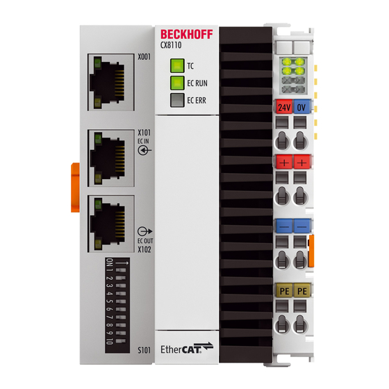
Product overview Structure Fig. 1: Sample configuration of a CX8110 Embedded PC. Table 2: Legend for the configuration. Component Description The DIP switches can be used to define the Explicit Device DIP switch [} 30] (S101). Identification for the EtherCAT slave interfaces (X101, X102). -
Page 14: Name Plate
Product overview Name plate The CX8110 Embedded PC features a name plate on the left-hand side of the housing. Fig. 2: CX8110 name plate. Table 3: Legend for the name plate. Description Information on the power supply unit. 24 V DC, 4 A max. MAC address of the Ethernet interface X001. -
Page 15: Ethernet Interfaces
Product overview Ethernet interfaces You can program and commission the CX8110 Embedded PC via the X001 Ethernet interface. The Ethernet interface achieves speeds of 10 / 100 Mbit/s. Fig. 3: Ethernet interface X001, X101, X102. The LEDs on the left of the interface indicate the connection status. The upper LED (LINK/ACT) indicates whether the interface is connected to a network. - Page 16 This cable has an outer shield of laminated aluminum and plastic foil. S/FTP Screened/foiled shielded twisted-pair (shielded with copper braid and aluminum foil) Has a laminated aluminum shield with a copper braid on top. Such cables can provide up to 70 dB reduction in interference power. Version: 1.4 CX8110...
- Page 17 This identification refers to a cable with a shield for each of the two wires as well as an outer shield. Industrial Twisted-Pair The structure is similar to that of S/STP, but, in contrast to S/STP, it has only two pairs of conductors. CX8110 Version: 1.4...
-
Page 18: Microsd Card
Product overview MicroSD card The basic equipment of the CX8110 includes a 512 MB MicroSD card. You can optionally order the Embedded PC with a larger MicroSD card (1 GB, 2 GB, 4 GB or 8 GB). The cards employed are SLC memory with extended temperature range for industrial applications. Use exclusively MicroSD cards approved by Beckhoff. -
Page 19: Commissioning
Commissioning Commissioning Mounting 5.1.1 Dimensions 71 mm 73 mm 68 mm CX8110 X001 24V 0V X101 X102 S101 Fig. 4: Dimensions of the CX81xx Embedded PC. Technical drawings in DWG and STP formats can be found at: http://www.beckhoff.com CX8110 Version: 1.4... -
Page 20: Note The Permissible Installation Positions
24V 0V 24V 0V 24V 0V 24V 0V 24V 0V X101 X102 S101 KL 1002 KL 1002 KL 2134 KL 2134 KL 9010 KL 9010 BECKHOFF BECKHOFF BECKHOFF BECKHOFF BECKHOFF BECKHOFF Fig. 5: Embedded PC CX8110, horizontal installation position. Version: 1.4 CX8110... -
Page 21: Fig. 6 Embedded Pc Cx8110, Vertical Installation Position
1 2 3 4 5 6 9 10 Fig. 6: Embedded PC CX8110, vertical installation position. Fig. 7: Embedded PC CX8110, horizontal installation position. Ensure that Bus Terminals that are connected to the Embedded PC are designed for operation in vertical or horizontal position. -
Page 22: Securing On Mounting Rail
Secure the Embedded PC on the mounting rail as follows: 1. Place the Embedded PC at the front of the mounting rail. Slightly press the Embedded PC onto the mounting rail until a soft click can be heard and the Embedded PC has latched. CX8110 X001 24V 0V... -
Page 23: Connecting The Power Supply
• Standard EN 60204-1:2006, section 6.4.1:b stipulates that one side of the circuit, or a point of the energy source for this circuit must be connected to the protective earth conductor system. Connection example Us 24 V (DC) CX8110 X001 24V 0V X101... -
Page 24: Table 7 Required Wire Cross-Sections And Strip Lengths
The CX8110 Embedded PCs are UL certified. The corresponding UL label can be found on the type plate. The CX8110 Embedded PCs can thus be used in areas in which special UL requirements have to be met. These requirements apply to the system voltage (Us) and to the power contacts (Up). Application areas without special UL requirements are not affected by UL regulations. -
Page 25: Configuration
Operating system The Microsoft Windows Embedded Compact 7 operating system is used on the CX8110 Embedded PC. This operating system is optimized for the CX8110 Embedded PC. This means that not all features of Windows Embedded Compact 7 are available. -
Page 26: Features Included
Configuration 6.1.1 Features included Features CX8110 XML DOM XML Minimal Parser DCOM COM Storage Winsock TCP/IP TCP/IPv6 Firewall Network Utilities (IpConfig, Ping, Route) Object Exchange Protocol OBEX Message Queuing MSMQ UPnP Control Point Device Host SOAP Client Server Server File Server (SMB/CIFS) -
Page 27: Update Image
The new image will be copied directly to the MicroSD card in order to update the image of the Embedded The new image is made available by Beckhoff Service. Perform the update only after consulting with Beckhoff Service. -
Page 28: Ftp Server
FTP Server Restricted access through firewall From image version "CX8100_WEC7_LF_v604h_TC31_B4022.20", the firewall for the CX8110 is enabled by default. This means that a passive FTP connection (as used by Microsoft, for example) cannot be established. We therefore recommend using active FTP access. Enter TCP ports 20 and 21 in the firewall. - Page 29 FTP. On the server side, the firewall should be configured such that the data port of the server can be reached by the client. Many FTP servers offer the option to configure the data ports to be used. CX8110 Version: 1.4...
-
Page 30: Dip Switch
The DIP switches (S101) can be used to define the Explicit Device Identification for the EtherCAT slave interfaces (X101, X102). This enables an CX8110 to be swapped with another CX8110 during operation. Explicit Device Identification is a value that enables the individual CX8110s to be distinguished. -
Page 31: Ip Address
Under Windows Embedded Compact 7, the X001 Ethernet interface is displayed as EMAC1. Fig. 9: Ethernet interface with Windows Embedded Compact 7. EMAC1 (X001) As standard, DHCP is active and the IP address is assigned automatically. You can deactivate DHCP and assign a static IP address. CX8110 Version: 1.4... -
Page 32: Web Service
Start the Beckhoff Device Manager as follows: 1. Open a web browser on the host PC. 2. Enter the IP address or the host name of the Industrial PC in the web browser to start the Beckhoff Device Manager. • Example with IP address: https://169.254.136.237/config •... -
Page 33: Enabling A Remote Display
Enable the remote display as follows: 1. Open a web browser on the host PC. 2. Enter the IP address or the host name of the Industrial PC in the web browser to start the Beckhoff Device Manager. • Example with IP address: https://169.254.136.237/config •... -
Page 34: Starting A Remote Connection
Requirements: • Remote Display is active. See: Enabling a remote display. • Host name of the Embedded PC. • Remote Display Control (CERHOST). Download under: https://infosys.beckhoff.com/content/1033/ CX8110_HW/Resources/zip/5047075211.zip Start the remote connection as follows: 1. Unpack the zip file on the host PC and run cerhost.exe. -
Page 35: Twincat
2. In the tree view on the left click on SYSTEM, and then Choose Target. 3. Click on Search (Ethernet). 4. Type the host name or the IP address of the device into the Enter Host Name / IP box and press [Enter]. CX8110 Version: 1.4... - Page 36 The new target system and the host name are displayed in the menu bar. Using this procedure you can search for all available devices and also switch between the target systems at any time. Next, you can append the device to the tree view in TwinCAT. Version: 1.4 CX8110...
-
Page 37: Scanning For Devices
ð The devices are created in the tree view. Depending on the connected terminals, either a Bus Coupler or an EtherCAT coupler with the associated terminals will be displayed. In the next step you can create a small program. CX8110 Version: 1.4... -
Page 38: Creating Process Data
BYTE (Dummy3) Byte Offset 4 UDINT Byte Offset 4 UDINT Sum: 8 bytes Sum 8 bytes Create process data as follows: 1. Under Devices in the tree view on the left, right-click on Inputs to create input variables. Version: 1.4 CX8110... - Page 39 3. Select the required variables and confirm with OK. Click the Create Array Type button to create data structures. ð You have successfully created input variables. Repeat the steps to create output variables in the same way. CX8110 Version: 1.4...
-
Page 40: Creating A Plc Project
2. In the context menu click on Add New Item and select the Standard PLC Project. 3. In the tree view click on the newly created PLC project, then double-click on MAIN (PRG) under POUs. 4. Write a small program, as shown in the diagram below. Version: 1.4 CX8110... - Page 41 ð You have successfully created a PLC project and added the project in TwinCAT. A PLC instance is created with the variables for the inputs and outputs from the PLC project. In the next step you can link the variables with the hardware. CX8110 Version: 1.4...
-
Page 42: Linking Variables
ð You have successfully linked variables with the hardware. Use Activate Configuration to save and activate the current configuration. Next, the configuration can be loaded to the Embedded PC in order to start TwinCAT automatically in Run mode and then start the PLC project. Version: 1.4 CX8110... -
Page 43: Using Explicit Device Identification
Explicit Device Identification is a value that enables the individual CX8110s to be distinguished. This enables an CX8110 to be swapped with another CX8110 during operation. The value can be set with the DIP switches or in TwinCAT. If the value is to be set with the DIP switches, this setting requires one-time activation in TwinCAT. -
Page 44: Distributed Clocks (Dc)
Synchronization is best illustrated by two clocks, a master clock and a slave clock. The CX8110 is the slave clock and must follow the master clock. The two clocks do not have to have the same absolute time. Rather, the time difference (DcToTcTimeDiff) to the master clock becomes a constant after synchronization. -
Page 45: Enabling Distributed Clocks
Enabling distributed clocks This chapter explains how to enable distributed clocks (DC) in the slave interface of the CX8110. To this end, the CX8110 is scanned in TwinCAT, and the slave interface and the lower master of the CX8110 are created. -
Page 46: Configuring The Lower Master
Configuration 6.6.2 Configuring the lower master This chapter explains how to configure the lower master (EtherCAT master) of the CX8110. Once the configuration is complete, the lower master fetches the distributed clock from the slave interface. Proceed as follows: 1. In the tree view on the left, click on the EtherCAT master of the CX8110. -
Page 47: Diagnostics On The Slave Side
CX8110 may take longer. The shorter the sync task, the faster and better the CX8110 is tuned. The disadvantage is a higher CPU load. So the rule is: as fast as possible, but without overloading the CPU. Make sure the CPU load is below 60%. -
Page 48: Configuring The Upper Master
1 and 2 ms. Proceed as follows: 1. In the tree view click on the EtherCAT slave. This is the CX8110 connected to the upper master. 2. Click the DC tab. 3. Under Operation Mode, enable the DC Synchron option. -
Page 49: Programming
Table 14: Storage location and names of the files in TwinCAT 3. Development environment File path File name TwinCAT 3 \\TwinCat\3.1\Boot\Plc Port_85x.bootdata Port_85x.bootdata-old (backup) The x in the file name stands for the number of the runtime system. CX8110 Version: 1.4... - Page 50 Always call the function block from the PLC and always use the fastest task to do so. In the case of a power failure Beckhoff recommends not calling the rest of the application in order to ensure that sufficient time remains for writing the data.
-
Page 51: Fb_S_Ups_Cx81Xx
A QuickShutdown is performed automatically in the eSUPS_WrPersistData_Shutdown mode (standard setting) after the storage of the persistent data. In the eSUPS_WrPersistData_NoShutdown mode only the persistent data are saved, no QuickShutdown is performed. In eSUPS_ImmediateShutdown mode a quick shutdown is executed immediately, without saving data. CX8110 Version: 1.4... - Page 52 VAR_GLOBAL eGlobalSUpsState : E_S_UPS_State; (*current ups state*) END_VAR eGlobalSUpsState: Internal state of the function block as global copy of VAR_OUTPUT eState: For values see E_S_UPS_State Requirements Development environ- Target platform Hardware PLC libraries to include ment TwinCAT v3.1 CX81xx Seconds UPS Tc2_SUPS Version: 1.4 CX8110...
-
Page 53: Data Types
The corresponding namespace is 'TwinCAT_SystemInfoVarList'. This must be specified for use in a library, for example. TYPE PlcAppSystemInfo STRUCT ObjId : OTCID; TaskCnt : UDINT; OnlineChangeCnt : UDINT; Flags : DWORD; AdsPort : UINT; BootDataLoaded : BOOL; OldBootData : BOOL; AppTimestamp : DT; KeepOutputsOnBP : BOOL; ShutdownInProgress : BOOL; LicensesPending : BOOL; BSODOccured : BOOL; TComSrvPtr : ITComObjectServer; AppName : STRING(63); ProjectName : STRING(63); END_STRUCT END_TYPE CX8110 Version: 1.4... -
Page 54: Function F_Cx81Xx_Address
ProjectName Name of the project Function F_CX81xx_ADDRESS This function reads the position of the DIP switch of the CX8110. One possible application is that you can activate different program parts in the PLC depending on the switch position. VAR_INPUT VAR_INPUT iCX_Typ : INT; (* Use product code without ‘CX’... -
Page 55: Table 15 Description Of The Softrtc Registry Key
As a result, the RTC on the operating system is slow. If you have noticed that the RTC is slow and the time on the CX8110 is also slow, you can apply the following troubleshooting procedure. -
Page 56: Ethernet X001 Interface
Ethernet device in the world. The MAC-ID consists of two parts. The first part (i.e. the first 3 bytes) is a manufacturer identifier. The identifier for Beckhoff is 00 01 05. The next 3 bytes are assigned by the manufacturer and implement a unique serial number. The MAC-ID can, for example, be used for the BootP protocol in order to set the TCP/IP number. -
Page 57: Fig. 14 Protocols Running On Top Of Tcp/Ip And Udp/Ip
Both of these protocols are implemented in parallel on the Bus Coupler, so that no configuration is needed to activate the protocols. Fig. 14: Protocols running on top of TCP/IP and UDP/IP. ADS can be used on top of either TCP or UDP, but ModbusTCP is always based on TCP/IP. CX8110 Version: 1.4... -
Page 58: Topology Example
Fig. 16: The ADS protocol as a transport layer within TwinCAT. The ADS protocol runs on top of the TCP/IP or UDP/IP protocols. It allows the user within the Beckhoff system to use almost any connecting route to communicate with all the connected devices and to parameterize them. -
Page 59: Fig. 17 Structure Of The Ads Communication
ADS-DLL You can link the ADS-DLL (DLL: Dynamic Link Library) into your C program. The OPC interface is a standardized interface for communication used in automation technology. Beckhoff offer an OPC server for this purpose. Protocol The ADS functions provide a method for accessing the Bus Coupler information directly from the PC. ADS function blocks can be used in TwinCAT for this. -
Page 60: Error Handling And Diagnosis
Display Meaning TwinCAT Status LED: TwinCAT is in Run mode (green). CX8110 TwinCAT is in Stop mode (red). TwinCAT is in Config mode (blue). No function ex factory. The LED can be parameterized for user-specific diagnostic messages (see: F_CX8190_LED_WD function). -
Page 61: Table 18 K-Bus Err Led, Fault Description And Troubleshooting
For some error the LED "K-BUS ERR" does not go out, even if the error was rectified. Switch the power supply for the power supply unit off and back on again to switch off the LED after the error has been rectified. CX8110 Version: 1.4... -
Page 62: Table 19 Description Of The State Variable Values
Bit 10 K-bus output update not yet complete. Bit 11 Watchdog. Bit 15 Acyclic K-bus function active (e.g. K-bus reset). If there is a K-bus error, this can be reset via the IOF_DeviceReset function block (in the TcIoFunctions.lib). Version: 1.4 CX8110... -
Page 63: E-Bus
Up 24 V Power supply for terminal bus. The LED lights green if the power supply is correct. L / A E-bus not connected. E-bus connected / no data traffic. flashes E-bus connected / data traffic on the E-bus. CX8110 Version: 1.4... -
Page 64: Care And Maintenance
Only use original batteries and ensure that the positive and negative poles are inserted correctly. The battery must be replaced every 5 years. Spare batteries can be ordered from Beckhoff Service. A battery of type CR2032 is used for the Embedded PC. -
Page 65: Technical Data
Technical data Technical data Table 22: Technical data, dimensions and weights. CX8110 Dimensions (W x H x D) 71 mm x 100 mm x 73 mm Weight 230 g Table 23: Technical data, general data. Technical data CX8110 Processor ARM Cortex™-A9, 800 MHz 32-bit... -
Page 66: Table 26 Technical Data, Ethernet Interface X001
Table 26: Technical data, Ethernet interface X001. Technical data Description Data transfer medium 4 x 2 twisted pair copper cables category 5 (100 MBit/s) Cable length 100 m from switch to CX8110 Data transfer rate 10/100 MBit/s Topology star wiring Protocols... -
Page 67: Appendix
CX1900-0128 4 GB MicroSD card CX1900-0130 8 GB MicroSD card Table 29: Spare battery for CX systems. Order number Description CX1900-0102 Replacement battery, suitable for CX10x0, CX50x0, CX51x0, CX52x0, CX90x0, CX20xx and CX8100 – Lithium button cell type CR2032, 3 V/225 mAh CX8110 Version: 1.4... -
Page 68: Certifications
FCC Approval for Canada FCC: Canadian Notice This equipment does not exceed the Class A limits for radiated emissions as described in the Radio Interference Regulations of the Canadian Department of Communications. Version: 1.4 CX8110... -
Page 69: Support And Service
Please contact your Beckhoff branch office or representative for local support and service on Beckhoff products! The addresses of Beckhoff's branch offices and representatives round the world can be found on her internet pages: https://www.beckhoff.com You will also find further documentation for Beckhoff components there. - Page 70 List of tables List of tables Table 1 Dimensions and weight of the CX8110 Embedded PC............... Table 2 Legend for the configuration......................Table 3 Legend for the name plate......................Table 4 Ethernet interface X001, pin assignment..................Table 5 EtherCAT slave interface X101 and X102, PIN assignment............
- Page 71 Structure of the Ethernet protocol....................Fig. 14 Protocols running on top of TCP/IP and UDP/IP................. Fig. 15 Topology example, CX8110 connected with other CX8110 via EtherCAT........Fig. 16 The ADS protocol as a transport layer within TwinCAT............... Fig. 17 Structure of the ADS communication...................
- Page 73 More Information: www.beckhoff.com/CX8110 Beckhoff Automation GmbH & Co. KG Hülshorstweg 20 33415 Verl Germany Phone: +49 5246 9630 info@beckhoff.com www.beckhoff.com...
Need help?
Do you have a question about the CX8110 and is the answer not in the manual?
Questions and answers