Beckhoff CX20 2 Series Manual

Beckhoff CX20 2 Series Manual

Embedded pc
Table of Contents

Advertisement

Manual | EN
CX20x2
Embedded PC
6/30/2020 | Version: 1.7

Advertisement

Table of Contents
loading

Summary of Contents for Beckhoff CX20 2 Series

  • Page 1 Manual | EN CX20x2 Embedded PC 6/30/2020 | Version: 1.7...
  • Page 3: Table Of Contents

    Table of contents Table of contents 1 Notes on the documentation ........................ 5 Representation and structure of warnings .................. 6 Related documents.......................... 7 Documentation issue status ...................... 7 2 For your safety............................ 8 Intended use ............................ 8 Staff qualification .......................... 8 Safety instructions .......................... 9 3 Transport and storage.......................... 10 4 Product overview............................. 11 Configuration of the basic CPU module .................. 13 Name plate ............................ 14...
  • Page 4 Table of contents Starting the Beckhoff Device Manager .................... 41 TwinCAT ............................ 42 7.3.1 Tree view .........................  42 7.3.2 Searching for target systems ...................  43 7.3.3 Scanning an Embedded PC ....................  45 7.3.4 Configuring EtherCAT cable redundancy................  46 7.3.5 Using a hardware watchdog ....................  49 8 NOVRAM.............................. 50...
  • Page 5: Notes On The Documentation

    EP1590927, EP1789857, EP1456722, EP2137893, DE102015105702 with corresponding applications or registrations in various other countries. ® EtherCAT is registered trademark and patented technology, licensed by Beckhoff Automation GmbH, Germany Copyright © Beckhoff Automation GmbH & Co. KG, Germany. The reproduction, distribution and utilization of this document as well as the communication of its contents to others without express authorization are prohibited.
  • Page 6: Representation And Structure Of Warnings

    Notes on the documentation Representation and structure of warnings The following warnings are used in the documentation. Read and follow the warnings. Warnings relating to personal injury: DANGER Serious risk of injury Hazard with high risk of death or serious injury. WARNING Risk of injury Hazard with medium risk of death or serious injury.
  • Page 7: Related Documents

    Further information on the devices of the CX2000 Embedded PC series can be found in the associated documentation. Read and follow in particular the sections on safety in this documentation. The following important documentation can be viewed at and downloaded from the Beckhoff website: http://www.beckhoff.de...
  • Page 8: For Your Safety

    Beckhoff Automation GmbH & Co. In addition, the following actions are excluded from the liability of Beckhoff Automation GmbH & Co. KG: • Failure to comply with this documentation.
  • Page 9: Safety Instructions

    • The sensitivity of a PC against malicious software increases with the number of installed and active software. • Uninstall or disable unnecessary software. Further information about the safe handling of networks and software can be found in the Beckhoff Information System: http://infosys.beckhoff.de...
  • Page 10: Transport And Storage

    Transport and storage Transport and storage Transport NOTE Short circuit due to moisture Moisture can form during transport in cold weather or in the event of large temperature fluctuations. Avoid moisture formation (condensation) in the Embedded PC, and leave it to adjust to room temperature slowly.
  • Page 11: Product Overview

    Product overview Product overview The CX2000 product family consists of individual modules, which can be assembled to form a customized Embedded PC. The CX2000 product family consists of: • basic CPU modules, • CX2100 power supply units, • system, fieldbus and extension modules, •...
  • Page 12: Table 2 Available Optional Interfaces For The Cx20X2

    Product overview The basic CPU module can be ordered ex factory with an optional interface. The optional interface cannot be retrofitted. Table 2: Available optional interfaces for the CX20x2. CX20x0-xxxx Optional interfaces CX20x0-N010 DVI-D, additional DVI-D socket for clone and extended display mode. CX20x0-N011 DisplayPort, additional DisplayPort for clone and extended display mode CX20x0-N030 RS232, D-sub connector, 9-pole.
  • Page 13: Configuration Of The Basic Cpu Module

    Product overview Configuration of the basic CPU module Fig. 2: Example of a CX2072 Embedded PC. Table 3: Legend for the configuration of the basic CPU module Component Description Multi-pole connection (left) Extension through system modules and fieldbus modules of type CX2500. Space for interfaces such as RS232, EtherCAT, CANopen or Optional interface [} 22] others.
  • Page 14: Name Plate

    Product overview Name plate The CX20x2 Embedded PC features a name plate on the left-hand side of the housing. Fig. 3: CX20x2 name plate. Table 4: Legend for the name plate. Description Information on the power supply unit. 24 V DC, 4 A max. MAC addresses of the integrated Ethernet ports. By default, the host name is formed from CX plus the last 3 bytes of the MAC address: for example, the MAC address: 00-01-05-aa-bb-cc results in the host name CX-aabbcc.
  • Page 15: Module Overview

    Product overview Module overview CX20x2 Version: 1.7...
  • Page 16: Types

    Product overview Types The basic CPU module can be ordered with different hardware and software options. Use this overview in conjunction with the information on the name plate to ascertain the hardware, operating system and TwinCAT version of the basic CPU module. Fig. 4: Nomenclature for the basic CPU module.
  • Page 17: Architekture Overview

    Product overview Architekture overview The many-core CX20x2 Embedded PCs all have the same architecture, which is structured as follows: Fig. 5: CX20x0 architecture overview. The CX20x2 Embedded PCs are based on the Broadwell microarchitecture developed by Intel. The following CPUs are used: •...
  • Page 18 Product overview • 1 PCIe to FPGA for K-/E-bus and NOVRAM. • 2x SATA internal via the multi-pole connection (right). • 2x USB internal via the multi-pole connection (right). The interfaces (USB, DVI, and LAN) are standard interfaces. Devices that meet the corresponding standard can be connected to and operated at these interfaces.
  • Page 19: Description Of The Interfaces

    Description of the interfaces Description of the interfaces USB 3.0 interfaces (X100, X101, X102, X103) Fig. 6: USB 3.0 interfaces X100, X101, X102, X103. The Embedded PC has four independent USB 3.0 interfaces for connecting keyboards, mice, touchscreens and other input or data storage devices. Fig. 7: USB 3.0 interface, pin numbering.
  • Page 20: Ethernet Rj45 (X000, X001)

    Description of the interfaces Ethernet RJ45 (X000, X001) The two Ethernet interfaces are independent; no switch is integrated. The independent Ethernet interfaces can be configured in different ways. In delivery state the Ethernet interfaces (X000, X001) are configured for EtherCAT communication. Note that an additional switch is required for a line topology.
  • Page 21: Dvi-I (X200)

    The DVI-I interface (X200) transfers digital data and is suitable for connection to digital or analog monitors. The resolution at the display or the Beckhoff Control Panel depends on the distance from the display device. The maximum distance is 5 m. Beckhoff offers various Panels with an integrated “DVI extension”. These make a cable length of up to 50 meters possible.
  • Page 22: Optional Interfaces

    N010 interface (DVI-D interface) is used, the first DVI-I interface can be operated either in VGA mode or in DVI mode. The resolution at the display or the Beckhoff Control Panel depends on the distance from the display device. The maximum distance is 5 m. Beckhoff offers various Panels with an integrated “DVI extension”.
  • Page 23: Displayport (N011)

    Description of the interfaces 5.4.2 DisplayPort (N011) The DisplayPort transfers image and audio signal at the same time and is therefore suitable for connecting panels or monitors to the Embedded PC. Fig. 12: DisplayPort X300. Version 1.1a of the DisplayPort (DisplayPort++) is installed on the Embedded PC. Adapters from DisplayPort to DVI-D or DisplayPort to HDMI can be used to connect monitors without DisplayPort to the Embedded PC.
  • Page 24: Rs232 (N030)

    Description of the interfaces 5.4.3 RS232 (N030) The optional N030 interface provides an RS232 interface (X300). The RS232 interface is implemented on a 9-pin D-sub connector. Fig. 13: RS232 interface X300 with pin numbering. The maximum baud rate on both channels is 115 kbit. The interface parameters are set via the operating system or from the PLC program.
  • Page 25: Rs422/Rs485 (N031)

    Description of the interfaces 5.4.4 RS422/RS485 (N031) The optional N031 interface provides an RS422 or RS485 interface (X300). The interface is implemented on a 9-pin D-sub connector. Fig. 14: RS485 interface X300 with pin numbering. The maximum baud rate on both channels is 115 kbit. The interface parameters are set via the operating system or from the PLC program.
  • Page 26: Ethercat Slave (B110)

    Receive + connected reserved RD - Receive - connected reserved For the optional EtherCAT slave interface (B110), documentation with further information is available for download from the Beckhoff website: https://www.beckhoff.de/german/download/epc.htm?id=71003127100362 Document name CXxxx0-B110 optional interface EtherCAT slave. Version: 1.7 CX20x2...
  • Page 27: Profibus (X310)

    PROFIBUS line D sub B red Pin 3 A green Pin 8 For the optional PROFIBUS interface (x310), documentation with further information is available for download from the Beckhoff website: https://www.beckhoff.de/german/download/epc.htm?id=71003127100362 Document name CXxxx0-x310 optional Profibus interface. CX20x2 Version: 1.7...
  • Page 28: Canopen (X510)

    CAN ground (internally connected to pin 3) CAN high (CAN+) not used not used For the optional CANopen interface (x510), documentation with further information is available for download from the Beckhoff website: https://www.beckhoff.de/german/download/epc.htm?id=71003127100362 Document name CXxxx0-x510 optional CANopen interface. Version: 1.7...
  • Page 29: Profinet Rt (X930)

    Description of the interfaces 5.4.8 PROFINET RT (x930) Fig. 19: PROFINET RT interface X300. Fig. 20: PROFINET RT LAN interface, pin numbering. Table 22: PROFINET RT interface, pin assignment. Signal Description TD + Transmit + TD - Transmit - RD + Receive + connected reserved RD -...
  • Page 30: Commissioning

    Commissioning Commissioning Selecting the appropriate CX2100 power supply unit The basic CPU module requires a power supply unit of the type CX2100-0014 or CX2100-0914 for the power supply. Connect the power supply unit to the multi-pin port on the right of the basic CPU module. None of other power supply units of the CX2000 family are suitable for the CX20x2 Embedded PC.
  • Page 31: Mounting

    Commissioning Mounting 6.2.1 Attaching the power supply unit The basic CPU module requires the CX2100-0014 or CX2100-0914 power supply unit for the power supply. Plug the power supply unit into the high-pole connection on the right on the basic CPU module. None of other power supply units of the CX2000 family are suitable for the CX20x2 Embedded PC.
  • Page 32: Note The Permissible Installation Positions

    Commissioning 6.2.3 Note the permissible installation positions NOTE Increased heat generation The Embedded PC may overheat if the minimum distances are not adhered to. • The Embedded PC may only be operated at ambient temperatures of up to 50 °C. Ensure adequate ven- tilation.
  • Page 33: Fig. 23 Cx20X2 Embedded Pc, Vertical Mounting Position

    Commissioning Vertical mounting position The minimum distance of at least 30 mm above and below the cooling fins of the Embedded PC must also be adhered to when the device is mounted vertically. Ensure that any Bus Terminals connected to the Embedded PC are designed for operation in vertical position.
  • Page 34: Attaching On Mounting Rail

    Commissioning 6.2.4 Attaching on mounting rail The housing is designed such that the Embedded PC can be pushed against the mounting rail and latched onto it. Requirements: • Mounting rail of type TS35/7.5 or TS35/15 according to DIN EN 60715. Secure the Embedded PC on the mounting rail as follows: 1.
  • Page 35: Cfast Card Installation And Removal

    A CFast card is a non-volatile memory. Data to be retained in the event of a power failure should be saved on the CFast card. The CFast cards supplied by Beckhoff are industrial cards with an increased number of write cycles and an extended temperature range (+85 °C).
  • Page 36: Installing Passive Ethercat Terminals

    Commissioning 6.2.6 Installing passive EtherCAT Terminals Incorrectly installed passive EtherCAT Terminals The E-bus signal between an Embedded PC and the EtherCAT Terminals can be impaired due to incorrectly installed passive EtherCAT Terminals. Passive EtherCAT Terminals should not be installed directly on the power supply unit. EtherCAT Terminals that do not take part in active data exchange are referred to as passive terminals.
  • Page 37: Connecting The Power Supply

    Commissioning Connecting the power supply NOTE Damage to the Embedded PCs The Embedded PCs may be damaged during wiring. • The cables for the power supply should only be connected in de-energized state. The CX2100-0014 power supply units require an external voltage source, which provides 24 V DC (-15% / +20%).
  • Page 38: Table 26 Required Wire Cross-Sections And Strip Lengths

    Commissioning The cables of an external voltage source are connected to the power supply unit with spring-loaded terminals. Table 26: Required wire cross-sections and strip lengths. Conductor cross-section 0,5 ... 2,5 mm AWG 20 ... AWG 14 Strip length 8 ... 9 mm 0.33 inch Connect the Embedded PC as follows: 1.
  • Page 39: Switching On

    Commissioning Switching on Please ensure that the Embedded PC is fully configured before switching on the Embedded PC. Switch on the Embedded PC as follows: 1. Ensure that all extension, system and fieldbus modules are connected correctly. 2. Check whether the Embedded PC is mounted securely on the DIN rail and all required Bus Terminals are connected.
  • Page 40: Configuration

    Configuration Configuration Windows 10 IoT Enterprise LTSB 7.1.1 Identification of the Ethernet interfaces (X000, X001) Network and Sharing Center In the Network and Sharing Center the Ethernet interfaces (X000, X001) of the CX20x0 Embedded PC are identified as follows as standard: •...
  • Page 41: Starting The Beckhoff Device Manager

    Start the Beckhoff Device Manager as follows: 1. Open a web browser on the host PC. 2. Enter the IP address or the host name of the Industrial PC in the web browser to start the Beckhoff Device Manager. • Example with IP address: https://169.254.136.237/config •...
  • Page 42: Twincat

    Configuration TwinCAT 7.3.1 Tree view The Tree View chapter can be used as an example for creating a project without actual hardware. All devices and components of an Embedded PCs must be added manually in TwinCAT 3. The smallest possible configuration of a CX20x0 Embedded PC, consisting of a basic CPU module and a CX2100-0004 power supply unit, is displayed in the tree view of TwinCAT 3 as follows: Fig. 30: CX20x0 Embedded PC in the tree view of TwinCAT 3, with attached EtherCAT Terminals (left) or Bus Terminals (right).
  • Page 43: Searching For Target Systems

    Configuration 7.3.2 Searching for target systems Before you can work with the devices, you must connect your local computer to the target device. Then you can search for devices with the help of the IP address or the host name. The local PC and the target devices must be connected to the same network or directly to each other via an Ethernet cable.
  • Page 44 Configuration Enter the user name and password for the CX in the User Name and Password fields and click OK. The following information is set as standard in CX devices: User name: Administrator Password: 1 6. If you do not wish to search for any further devices, click on Close to close the Add Route Dialog. The new device is displayed in the Choose Target System window.
  • Page 45: Scanning An Embedded Pc

    Configuration 7.3.3 Scanning an Embedded PC This step shows how to scan an Embedded PC in TwinCAT and then further configure it. Prerequisites for this step: • Selected target device. Add the Embedded PC as follows: 1. Start TwinCAT and open an empty project. 2.
  • Page 46: Configuring Ethercat Cable Redundancy

    LAN cables are avoided. CX2020 CX2100 5 VB 5 VB 5 VB 24V 0V enter EL 2032 EL 2032 EL 2032 EL 1110 BECKHOFF BECKHOFF BECKHOFF BECKHOFF 5 VB 5 VB 5 VB 24V 0V EK 1100 EL 2032 EL 2032 BECKHOFF...
  • Page 47 Configuration Configure EtherCAT cable redundancy as follows: 1. In the tree view click on the EtherCAT master. 2. Click on the EtherCAT tab, then Advanced Settings. 3. Click on Redundancy in the tree structure on the left. 4. Click on the option Second adapter, followed by the Search button. CX20x2 Version: 1.7...
  • Page 48 Configuration 5. Select the appropriate LAN connection according to your cabling at the Embedded PC. 6. Confirm the settings with OK. ð You have successfully configured cable redundancy. Under the Online tab the EtherCAT slaves are displayed, for which cable redundancy was configured. Under State the state of the individual EtherCAT slaves is displayed.
  • Page 49: Using A Hardware Watchdog

    Configuration 7.3.5 Using a hardware watchdog The function block FB_PcWatchdog_BAPI activates a hardware watchdog on the Embedded PC. The watchdog can be used to automatically restart systems that have entered an infinite loop or where the PLC has stopped. The watchdog is activated with bExecute = TRUE and nWatchdogTimeS >= 1s. Once the watchdog has been activated, the function block must be called cyclically and at shorter intervals than nWatchdogTimeS, because the Embedded PC automatically restarts if the set time is less than nWatchdogTimeS.
  • Page 50: Novram

    NOVRAM NOVRAM The NOVRAM can be used to reliably save important variable values, such as production data or counter values, in the event of a power failure. The memory size of the NOVRAM is limited and only suitable for smaller data quantities up to 63 kB. This chapter illustrates how the NOVRAM is •...
  • Page 51: Use Under Twincat 3

    NOVRAM Use under TwinCAT 3 Under TwinCAT 3 (from Build 4020) a delta algorithm is used to save data in the NOVRAM. The algorithm does not save all the variables in the NOVRAM. Instead, it searches for changes (delta function) compared to the previous cycle and only saves variables that have changed.
  • Page 52 NOVRAM 5. Click on Device (NOV-DP-RAM) in the tree view on the left-hand side and then on the tab Generic NOV-DP-RAM Device. 6. Click on the option PCI. 7. Right-click on Device (NOV-DP-RAM) in the tree view and then on Add New Item. 8.
  • Page 53: Creating And Linking Variables

    NOVRAM 8.1.2 Creating and linking variables Once you have created a Retain Handler in TwinCAT, you can declare variables in the PLC and link them to the Retain Handler. The variables have to be identified in the PLC with the keyword VAR_RETAIN. Prerequisite for this step: •...
  • Page 54 NOVRAM 4. Under Retain Hdl, select the Retain Handler that you have created. ð After selecting a Retain Handler as a target, the symbols in the tree view are linked and a mapping is created. In the tree view the variables are created from the PLC under the Retain Handler and linked to the variables from the PLC instance.
  • Page 55: Note The Write Speed Of The Retain Handler

    NOVRAM 8.1.3 Note the write speed of the Retain Handler The Retain Handler takes a certain amount of time to search for changes (delta function) in the variables and save them in the NOVRAM. The following diagrams provide an overview of how long the Retain Handler needs to save a particular data quantity in the NOVRAM.
  • Page 56: Deleting Variables Under The Retain Handler

    NOVRAM 8.1.4 Deleting variables under the Retain Handler If variables are deleted from the PLC, the link with the Retain Handler is cancelled. However, the variables continue to be shown under the Retain Handler and are not deleted automatically. Under TwinCAT 3 the variables have to be deleted manually. Prerequisites for this step: •...
  • Page 57: Error Handling And Diagnostics

    Error handling and diagnostics Error handling and diagnostics Basic CPU module 9.1.1 LEDs on the basic CPU module Display Meaning Power supply. The Power LED comes on when the device is connected to a live power supply unit (green). TwinCAT status LED: TwinCAT is in Run mode (green).
  • Page 58: Table 31 K-Bus Err Led, Fault Description And Troubleshooting

    Error handling and diagnostics Table 31: K-BUS ERR LED, fault description and troubleshooting. Error code Error code argu- Description Remedy ment Persistent, EMC problems. • Check power supply for undervoltage or continuous overvoltage peaks. flashing • Implement EMC measures. • If a K-bus error is present, it can be localized by a restart of the power supply (by switching it off and then on again) 3 pulses...
  • Page 59: Table 32 Description Of The State Variable Values

    Error handling and diagnostics Fig. 35: Status variable for error handling and diagnostics under TwinCAT. If the value is "0", the K-bus operates synchronous and without error. If the value is <> "0" there may be a fault, or it may only be an indication that the K-bus cycle is longer than the task. In which case it would no longer be synchronous with the task.
  • Page 60: Power Supply Terminal Leds In E-Bus Mode

    Error handling and diagnostics 9.1.3 Power supply terminal LEDs in E-bus mode The power supply unit checks the connected EtherCAT Terminals. The "L/A" LED is lit in E-bus mode. The "L/A" LED flashes during data transfer. Display Meaning Us 24 V Power supply for basic CPU module.
  • Page 61: Faults

    Fan is not turning. Fan faulty. Replace the fan cartridge. Please make a note of the following information before contacting Beckhoff service or support: 1. Precise device ID: CXxxxx-xxxx. 2. Serial number. 3. Hardware version. 4. Any interfaces (N030, N031,  B110, ...).
  • Page 62: Care And Maintenance

    Only use original batteries and ensure that the positive and negative poles are inserted correctly. The battery must be replaced every 5 years. Spare batteries can be ordered from Beckhoff Service. A battery of type CR2032 is used for the Embedded PC.
  • Page 63: Replace The Fan Cartridge

    Use the IPC diagnostics and monitor the fan speed to determine a fan fault. Access to the fan status is described in the documentation for the IPC diagnostics: https://download.beckhoff.com/download/document/ipc/industrial-pc/ipc_diagnose_de.pdf Replace the fan cartridge as follows: 1. Open the front flap.
  • Page 64 Care and maintenance 3. Push the new fan cartridge into the housing, with the contacts first. The guide rails at the fan match the guide rails in the housing. ð Close the front flap. You have successfully changed the fan cartridge if the fan starts up again. Version: 1.7 CX20x2...
  • Page 65: Decommissioning

    Decommissioning Decommissioning 11.1 Removing cables NOTE Electrical voltage If the power supply is switched on during dismounting, this can lead to damage to the Embedded PCs. • Switch off the power supply for the Embedded PCs during dismounting. Cabling Make a note of the wiring configuration, if you wish to restore it with another device. Before dismantling the Embedded PC, shut down the Embedded PC and switch off the power supply.
  • Page 66: Dismantling The Embedded Pc

    Decommissioning 11.2 Dismantling the Embedded PC The CX2000 Embedded PC series is a modular system and enables individual modules to be replaced or removed quite easily. This section describes how to remove devices from the CX2000 Embedded PC series. Requirements: •...
  • Page 67 Decommissioning ð Once the bar clips have been removed successfully, the modules can be separated from each other. Disposal The device must be fully dismantled in order to dispose of it. Electronic components must be disposed of according to national electronic waste regulations. CX20x2 Version: 1.7...
  • Page 68: Technical Data

    Technical data Technical data Table 36: Technical data, dimensions and weights. CX2042 CX2062 CX2072 Dimensions (W x H x D) 204 mm x 99 mm x 91 mm Weight approx. 1300 g Table 37: Technical data, general data. Technical data CX2042 CX2062 CX2072 Processor Intel® Xeon® D-1527 Intel®...
  • Page 69: Table 40 Technical Data, Graphic Specifications

    Technical data Table 40: Technical data, graphic specifications. Technical data Description Graphic system AMD E8860 Graphic memory 2 GB GDDR5 Graphics clock frequency 625 MHz Shader model DirectX OpenGL Table 41: Technical data, interfaces. Technical data Description 2 x RJ 45, 10/100/1000 Mbit/s 4 x USB 3.0 each rated at 900 mA, type A DVI-I Resolution on the monitor in pixels: 640 x 480 to 1920 x 1200...
  • Page 70: Appendix

    Appendix Appendix 13.1 Accessories Table 43: CFast cards Order number Description CX2900-0038 40 GB CFast card, 3D flash, extended temperature range CX2900-0040 80 GB CFast card, 3D flash, extended temperature range CX2900-0042 160 GB CFast card, 3D flash, extended temperature range larger capacities on request Table 44: HDD/SSD Order number...
  • Page 71: Certifications

    All products of the Embedded PC family are CE, UL and EAC certified. Since the product family is continuously developed further, we are unable to provide a full listing here. The current list of certified products can be found at www.beckhoff.com. FCC Approvals for the United States of America...
  • Page 72: Support And Service

    Beckhoff's branch offices and representatives Please contact your Beckhoff branch office or representative for local support and service on Beckhoff products! The addresses of Beckhoff's branch offices and representatives round the world can be found on her internet pages: http://www.beckhoff.com You will also find further documentation for Beckhoff components there.
  • Page 73: List Of Tables

    Table 25 Legend for the connection example..................... Table 26 Required wire cross-sections and strip lengths................Table 27 Access data for the Beckhoff Device Manager on delivery............Table 28 Legend for the tree view......................Table 29 Cable redundancy, hardware for sample configuration...............
  • Page 74 List of tables Table 45 Passive DVI-to-VGA adaptor....................... Table 46 Spare battery for CX systems...................... Table 47 Other spare parts......................... Version: 1.7 CX20x2...
  • Page 75 List of figures List of figures Fig. 1 Overview of the CX2000 product family with basic CPU module, power supply unit and mod- ules.............................. 
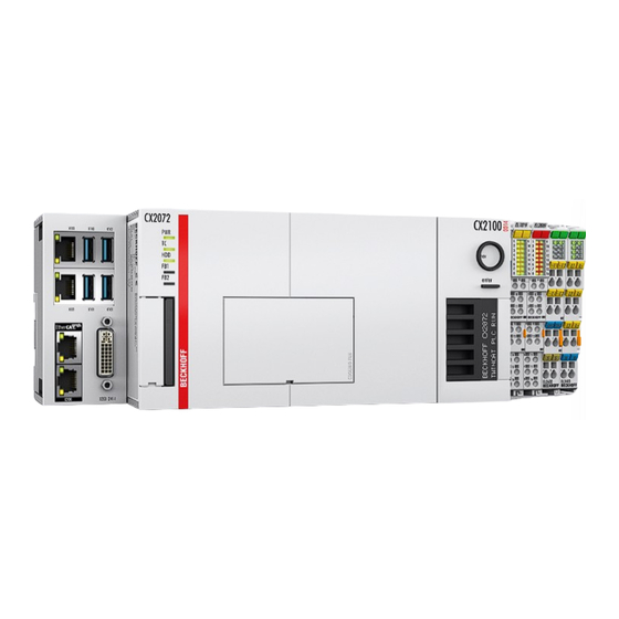
Fig. 2 Example of a CX2072 Embedded PC..................Fig. 3 CX20x2 name plate........................Fig.
  • Page 77 More Information: www.beckhoff.com/many-core-cx Beckhoff Automation GmbH & Co. KG Hülshorstweg 20 33415 Verl Germany Phone: +49 5246 9630 info@beckhoff.com www.beckhoff.com...

This manual is also suitable for:

Cx2042Cx2062Cx2072

Table of Contents