Table of Contents
Advertisement
Advertisement
Table of Contents

Related Manuals for Beckhoff CX50 0 Series


Summary of Contents for Beckhoff CX50 0 Series
- Page 1 CX50x0 - Hardware Documentation Version: 1.3 Datum: 2011-05-02...
-
Page 3: Table Of Contents
Table of contents Table of contents CX50x0 - Hardware Documentation 1. Foreword Notes on the documentation Safety instructions Documentation issue status 2. Product overview Appropiate use System overview CX5010 - Technical data CX5020 - Technical data Configurations Battery compartment Compact Flash slot Compact Flash card 3. - Page 4 Table of contents EtherCAT cabel redundancy Switching on / off BIOS Setup Standard CMOS Features IDE Primary Master IDE Primary Slave Advanced BIOS Features CPU Feature Advanced Chipset Features Integrated Peripherals OnChip IDE Device Onboard Device SuperIO Device USB Device Power Management Setup HPET Powermanagement DTS Powermanagement...
-
Page 5: Foreword
, TwinSAFE and XFC are registered trademarks of and licensed by Beckhoff Automation GmbH. Other designations used in this publication may be trademarks whose use by third parties for their own purposes could violate the rights of the owners. Patent Pending... -
Page 6: Safety Instructions
All the components are supplied in particular hardware and software configurations appropriate for the application. Modifications to hardware or software configurations other than those described in the documentation are not permitted, and nullify the liability of Beckhoff Automation GmbH. Personnel qualification This description is only intended for the use of trained specialists in control, automation and drive engineering who are familiar with the applicable national standards. -
Page 7: Documentation Issue Status
Notes on the documentation Documentation Issue Status Version Changes Requirements for power supply added Changes on temperature range and K-bus diagnosis Changes on system interface N031 and DVI resolution first release preliminary version CX50x0 - Hardware Documentation... -
Page 8: Product Overview
Notes on the documentation 2. Product overview Intended use The CX5010 / CX5020 device series is a modular control system designed for top-hat rail installation. The system is scalable, so that the required modules can be assembled and installed in the control cabinet or terminal box as required. -
Page 9: System Overview
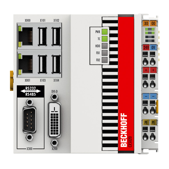
EtherCAT Terminals. Two independent Gigabit Ethernet ports and four USB 2.0 interfaces are available. A Beckhoff control panel or a commercially available DVI monitor can be connected to the DVI D interface. A serial port (RS232/RS422/RS485) or a fieldbus connection with master or slave function can be added as an optional interface as required. - Page 10 Notes on the documentation The complete programming of PLC, Motion Control and visualisation is transferable to all PC controls from Beckhoff, which is reassuring in cases where it becomes apparent during a project that more processing power is required after all.
-
Page 11: Cx5010 Technical Data
-25°C ... +60°C / -40°C ... +85°C Relative humidity 95 % no condensation Vibration/shock resistant conforms to EN 60068-2-6/EN 60068-2-27/ 29 EMC immunity/emission conforms to EN 61000-6-2 / EN 61000-6-4 Protection class IP 20 Technical data Further Information: www.beckhoff.de/CX5010 CX50x0 - Hardware Documentation... -
Page 12: Cx5020 - Technical Data
-25 C ... +60°C / -40 C ... +85°C Relative humidity 95 % no condensation Vibration/shock resistant conforms to EN 60068-2-6/EN 60068-2-27/ 29 EMC immunity/emission conforms to EN 61000-6-2 / EN 61000-6-4 Protection class IP 20 Further Information: www.beckhoff.de/CX5020 CX50x0 - Hardware Documentation... -
Page 13: Configurations
Notes on the documentation Types The CPU module can be equipped with different hardware and software options: "Windows CE" or "Windows Embedded Standard" are available as operating system. The TwinCAT automation software transforms a CX50x0 system into powerful PLC and Motion Control system that can be operated with or without visualisation. Further system interfaces (pre-installed in the factory) or fieldbus connections can be added to the basic CPU module. - Page 14 Notes on the documentation Windows TwinCAT TwinCAT CPU- without Windows Embedded without NC PTP Modul frequency Standard TwinCAT Runtime Runtime CX5020-0100 1,6 GHz CX5020-0110 1,6 GHz CX5020-0111 1,6 GHz CX5020-0112 1,6 GHz CX5020-0120 1,6 GHz CX5020-0121 1,6 GHz CX5020-0122 1,6 GHz CX5020-1100 1,6 GHz CX5020-1110...
-
Page 15: Battery Compartment
(negative pole on the left) Attention Never open the battery or throw it into a fire. The battery cannot be recharged. Battery maintenance The battery must be replaced every 5 years. Spare batteries can be ordered from Beckhoff Service Note CX50x0 - Hardware Documentation... -
Page 16: Compact Flash Slot
Notes on the documentation CF slot A Compact Flash slot is located at the front, which enables the storage medium to be replaced. In the basic module this should only be done in switched-off state, otherwise the system may crash. The Compact Flash card can be removed from the module for maintenance. -
Page 17: Compact Flash Card
These are industrial CF cards with a higher number of write/read cycles and an extended Note temperature range (+85 °C). Proper operation can only be guaranteed with CF cards from Beckhoff Automation GmbH! CX50x0 - Hardware Documentation... -
Page 18: Second-Ups
Notes on the documentation 3. Second-UPS S-UPS: capacitive seconds UPS The CX50x0 family features a built-in capacitive one-second UPS. It ensures a safe storage of the persistent application data on the Compact Flash card. Up to 1 MB of data can be saved. The UPS can be switched on and off via the BIOS: Phoenix - AwardBIOS CMOS Setup Utility PC Health Status SUSV... -
Page 19: Overview
Notes on the documentation Overview This library contains functions and function blocks which are needed in order to use the Seconds UPS. See sample project Sample_S_UPS.pro. Function Blocks Name Description FB_S_UPS Function block to use the Seconds UPS from the PLC. FB_NT_QuickShutdown Internal function block for the QuickShutdown, used by the FB_S_UPS. - Page 20 In case of the EWF the TwinCAT\Boot folder needs to be located on a not protected partition (see in the registry: HKEY_LOCAL_MACHINE\SOFTWARE\Beckhoff\TwinCAT\System\BootPrjPath). In case of the FBWF the TwinCAT\Boot folder needs to be excluded from the protection (see Beckhoff FBWF Manager, Exclusion Settings).
- Page 21 Notes on the documentation FUNCTION_BLOCK FB_S_UPS VAR_INPUT VAR_INPUT sNetID : T_AmsNetId := ''; (* '' = local netid *) iPLCPort : UINT := AMSPORT_R0_PLC_RTS1; (* PLC Runtime System for writing persistent data *) iUPSPort : UINT := 16#4A8; (* Port for reading Power State of UPS, dafault 16#4A8 *) tTimeout : TIME := DEFAULT_ADS_TIMEOUT;...
- Page 22 Notes on the documentation The tRecoverTime needs to be a little bit bigger than the maximum holding time of the UPS, since the UPS will shut off even if the power supply is restored. VAR_OUTPUT VAR_OUTPUT bPowerFailDetect : BOOL; (* TRUE while powerfailure is detected *) eState : E_S_UPS_State;...
-
Page 23: Fb_Nt_Quickshutdown
Notes on the documentation FUNCTION_BLOCK FB_NT_QuickShutdown The function block FB_NT_QuickShutdown is used to immediately reboot the PC without stopping TwinCAT or the operating system Windows. Attention: The function block FB_NT_QuickShutdown is used internally from FB_S_UPS and is not intended to be used elsewhere! FUNCTION_BLOCK FB_NT_QuickShutdown VAR_INPUT... -
Page 24: Functions
Notes on the documentation Functions FUNCTION F_GetVersionTcSUPS The function returns library version info. FUNCTION F_GetVersionTcSUPS : UINT VAR_INPUT nVersionElement : INT; END_VAR nVersionElement : Version element: 1 : major number; 2 : minor number; 3 : revision number; Development environment Target plattform PLC Libraries to include... -
Page 25: Datatypes
Notes on the documentation Datatypes E_S_UPS_Mode eSUPS_WrPersistData_Shutdown: Writing of persistent data and then a QuickShutdown eSUPS_WrPersistData_NoShutdown: only writing of the persistent data (no QuickShutdown) eSUPS_ImmediateShutdown: only QuickShutdown (no writing of persistent data) eSUPS_CheckPowerStatus: only check status (neither writing of persistent data nor a QuickShutdown) CX50x0 - Hardware Documentation... -
Page 26: E_S_Ups_State
Notes on the documentation E_S_UPS_State eSUPS_PowerOK: in all modes: Power supply is OK eSUPS_PowerFailure: in all modes: Power supply is faulty (only shown for one PLC cycle) eSUPS_WritePersistentData: in Mode eSUPS_WrPersistData_Shutdown: Writing of persistent data is active in Mode eSUPS_WrPersistData_NoShutdown: Writing of persistent data is active eSUPS_QuickShutdown: in Mode eSUPS_WrPersistData_Shutdown: QuickShutdown is active in Mode eSUPS_ImmediateShutdown: QuickShutdown is active... -
Page 27: Assembly And Connecting
Check the contents for visible shipping damage. If you notice any shipping damage or inconsistencies between the contents and your order, you should noti- fy Beckhoff Service. Danger of damage to the unit! During transport in cold conditions, or if the unit is subjected to extreme temperature swings, condensation on and inside the unit must be avoided. -
Page 28: Dimensions
Notes on the documentation Dimensions The following drawings show the dimensions of the CX50x0 devices. Dimensions CX50x0 - Hardware Documentation... - Page 29 Notes on the documentation Rear view CX50x0 - Hardware Documentation...
-
Page 30: Assembly On Mounting Rail
Notes on the documentation Installation on the mounting rail Snapping onto the mounting rail The CX50x0 can simply be snapped onto the mounting rail. To this end position the block on the mounting rail and push it slightly until it engages on the right-hand side. The is indicated by a distinct click. Use a screwdriver to push up the lock on the left-hand side, thereby turning it and causing it to engage audibly. - Page 31 Notes on the documentation Incorrect installation positions The CX50x0 system must not be operated vertically on the top-hat rail. A vertical position would lead to insufficient CPU ventilation, since the ventilation openings are located on the top and bottom of the housing. Installation of the system on its side would also lead to inadequate ventilation.
-
Page 32: Power Supply
Notes on the documentation Power supply This power supply unit is equipped with an I/O interface, which permits connection of the Beckhoff Bus Terminals. The power is supplied via the upper spring-loaded terminals labeled “24V” and “0V”. The supply voltage supplies the CX system ant the terminal Bus and Bus Terminal with a voltage of 24 V DC (- 15 %/+20 %). - Page 33 Notes on the documentation UL requirements Danger For the compliance of the UL requirements the CX-Controllers should only be supplied by a 24 V supply voltage, supplied by an isolating source and protected by means of a fuse (in accordance with UL248), rated maximum 4 Amp. ...
-
Page 34: Dvi-D Connection
The DVI-D interface transfers digital data and is suitable for connecting a digital display. The resolution at the display or the Beckhoff Control Panel depends on the distance from the display device. The maximum distance is 5 m. DVI-D interface The DVI interface does not use VGA signals, so that the connection of CRT VGA monitors to the CX1000 system using a DVI to VGA adapter is not possible. -
Page 35: Usb Connections
Notes on the documentation USB connections USB interface (X100 / X101 / X102 / X103): The CX50x0 has 4 independent USB interfaces, for connecting keyboards, mice, touch screens and other input or data storage devices. Keep an eye on the power consumption of the individual devices. Each port is limited to 500 mA. -
Page 36: Lan Connections
Notes on the documentation LAN connections LAN interface (X000/ X001) The CX50x0 systems have two independent LAN interfaces. Both ports are able to operate at speeds of 10 / 100 / 1000 Mbit. The LEDs on the left-hand sides of the RJ45 sockets indicate the status of the LAN connection. The upper LED indicates whether the port is connected to a network. -
Page 37: Rs232 Connection
Notes on the documentation RS232 connections (CX50x0-N030) The CX50x0-N030 system interface provides an RS232 interface, COM1 (X300). It is implemented on a 9-pole Sub- D pin strip. If more than one interface is required the system can be extended via the Terminal Bus (K- or E-bus) or Bus Terminals (KL/EL6001) which provide serial interfaces. -
Page 38: Rs422/Rs485 Connection
Notes on the documentation RS422/RS485 connections (CX50x0-N031) The CX50x0-N030 system interface provides an RS422 or RS 485 interface, COM1 (X300). It is implemented on a 9- pole Sub-D socket strip. If more than one interface is required the system can be extended via the Terminal Bus (K- or E-bus) or Bus Terminals (KL/EL6021) which provide serial interfaces. -
Page 39: Operating/Configuration
Minimum requirements: EtherCAT redundancy supplement EK1110 (bus extension) EK1100 (Bus Coupler) The supplement product on the Beckhoff website at http://download.beckhoff.com/download/Software/TwinCAT/Supplement/TwinCAT_EtherCAT_Redundancy/Install/Tc EcRedundancy.exe can be downloaded. The required licence key can be ordered from our sales division. The required couplers are ordered together with the other hardware. These components can then be used to configure the controller. The upper figure shows a minimum configuration example for cable redundancy. - Page 40 Failures of individual terminals are not covered. Note Further details can be found in the Beckhoff Information System under EtherCAT cable redundancy. Cases of failure The two possible failures are described in the example below.
- Page 41 Notes on the documentation In this example the supply line for coupler EK1100 is faulty. The EK1100 terminals continue to run despite the cable failure. The System Manager indicates the failure as follows: The interruption is indicated by "LNK_MIS B" and "LNK_MIS A". The next example shows a failure of the "return line": CX50x0 - Hardware Documentation...
- Page 42 Notes on the documentation In this case the second cable is faulty. The terminals at the coupler continue to run without malfunction. The System Manager indicates the behavior as follows: The interruption is indicated by "LNK_MIS C" at coupler EK1100. The EtherCAT ring is expandable.
-
Page 43: Switching On / Off
Notes on the documentation Switching on and off Switching on The power supply for the basic CPU module comes from the power supply unit. The basic CPU module starts automatically when the power supply unit is connected to the mains. Switching on for the first time When you switch on the PC for the first time, the pre-installed operating system (optional) will be started. -
Page 44: Bios Setup
Changes in the BIOS settings may only be implemented by appropriately trained staff. The CX50x0 systems are delivered by Beckhoff Automation GmbH in a preconfigured state and are therefore operational! The BIOS settings should only be executed by appropriately trained staff. -
Page 45: Standard Cmos Features
Notes on the documentation Standard CMOS Features This menu is used for setting date, time, hard disks, graphic mode and start-up behaviour. At the same time, information about the memory configuration determined by the system is provided. The memory configuration information cannot be changed. -
Page 46: Ide Primary Master
Notes on the documentation IDE Primary Master This menu is used to set the data for the hard disk connected as master to the first IDE bus. The hard disk data (size, number of cylinders, heads, sectors, pre-compensation and home position of the heads when the disk is switched off) are displayed automatically for the connected hard disk. - Page 47 Notes on the documentation LARGE Auto The following parameters are automatically determined and displayed. Capacity Storage capacity of the hard disk. This value is calculated from the individual hard disk parameters. Cylinder Define or set the number of cylinders. Depending on the BIOS version and the manufacturer it varies between 1,024 and 16,384 cylinders.
-
Page 48: Ide Primary Slave
Notes on the documentation IDE Primary Slave This menu is used to set the data for the hard disk connected as master to the first IDE bus. The hard disk data (size, number of cylinders, heads, sectors, pre-compensation and home position of the heads when the disk is switched off) are displayed automatically for the connected hard disk. - Page 49 Notes on the documentation The following parameters are automatically determined and displayed. Capacity Storage capacity of the hard disk. This value is calculated from the individual hard disk parameters. Cylinder Define or set the number of cylinders. Depending on the BIOS version and the manufacturer it varies between 1,024 and 16,384 cylinders.
-
Page 50: Advanced Bios Features
Notes on the documentation Advanced BIOS Features This menu is used to set the data for the hard disk connected as master to the first IDE bus. The hard disk data (size, number of cylinders, heads, sectors, pre-compensation and home position of the heads when the disk is switched off) are displayed automatically for the connected hard disk. - Page 51 Notes on the documentation Hard Disk CDROM (CD drive) ZIP100 (Zip-Drive) USB-FDD (USB-Floppy) USB-ZIP (USB Zip-Drive) USB-CDROM (USB CDROM) Legacy LAN (network) WIN CE Disabled (deactivated) Second Boot Device This setting is used for booting, if the first boot device is not available. First set the drive to be used as boot drive. Options: ...
- Page 52 Notes on the documentation chipset. With the Normal setting it is accessed via the keyboard controller. This option may speed up older computers. The first 64 K Block above 1 MB can be accessed in standard mode via address line A20. DOS will anchor itself there, if DOS=High is inserted in Config.sys.
-
Page 53: Cpu Feature
Notes on the documentation CPU Features This menu is used for setting the CPU behaviour with thermal profiles. Phoenix - AwardBIOS CMOS Setup Utility CPU Feature Thermal Management Disabled Item Help Limit CPUID MaxVal [Disabled] C1E Function [Disabled] CPU C State Capability [Disabled] Execute Disable Bit [Enabled]... -
Page 54: Advanced Chipset Features
Notes on the documentation Advanced Chipset Features This menu is used for memory functions settings. Such settings should be implemented cautiously since they can affect the stability of the whole system. Phoenix - AwardBIOS CMOS Setup Utility Advanced Chipset Features DRAM Timing Selectable [by SPD] Item... -
Page 55: Integrated Peripherals
Notes on the documentation Integrated Peripherals This option can be used for audio, multimedia and LAN interface settings. Phoenix - AwardBIOS CMOS Setup Utility Integrated Peripherals υ8; OnChip IDE Device [Press Enter] Item Help υ8; Onboard Device [Press Enter] υ8; SuperIO Device [Press Enter] υ8;... -
Page 56: Onchip Ide Device
Notes on the documentation Onchip IDE Device This menu is used for setting the IDE interfaces. Phoenix - AwardBIOS CMOS Setup Utility Onchip IDE Device IDE HDD Block Mode [Enabled] Item Help IDE Primary Master PIO [Auto] IDE Primary Master PIO [Auto] IDE Primary Master UDMA [Auto]... -
Page 57: Onboard Device
Notes on the documentation Onboard Device This menu is used for configuring the audio, multimedia and LAN interfaces. Phoenix - AwardBIOS CMOS Setup Utility Onboard Device Intel HD Audio Controller [Disabled] Item Help USB Client Routing [Disabled] SDIO/MMC Controller [Disabled] Onboard Lan Controller Enabled Console Redirect... -
Page 58: Superio Device
Notes on the documentation SuperIO Device This menu is used for configuring the USB and audio interfaces. Phoenix - AwardBIOS CMOS Setup Utility SuperIO Device Onboard Serial Port 1 [3F8/IRQ4] Item Help Onboard Serial Port 2 [2F8/IRQ3] UART Mode Select [Normal] RxD, TxD Active Hi, Lo... -
Page 59: Usb Device
Notes on the documentation USB Device Settings This menu is used for configuring the USB and audio interfaces. Phoenix - AwardBIOS CMOS Setup Utility Onboard Device USB 1.0 Controller [Enabled] Item Help USB 2.0 Controller [Enabled] USB Operation Mode [High Speed] USB Keyboard Function [Enabled] USB Storage Function... -
Page 60: Power Management Setup
Notes on the documentation Power Management Setup This menu is used for power management settings. Phoenix - AwardBIOS CMOS Setup Utility Power Management Setup Power-Supply Type [AT] Item Help Enabled APCI Function ACPI Suspend Type [S1(POS)] Soft-Off by PWR-BTTN [Instant-Off] υ8;... -
Page 61: Hpet Powermanagement
Notes on the documentation HPET power management This menu is used for HPET settings. Phoenix - AwardBIOS CMOS Setup Utility HPET Feature HPET Support [Enable] Item Help HPET Mode [32-bit mode] ↑ ↓ → ← :Move Enter:Select +/-/PU/PD:Value F10:Save ESC:Exit F1:Help F5: Previous Values F6: Fail-Safe Defaults F7: Optimized Defaults HPET Support Activates or deactivates HPET support . -
Page 62: Dts Powermanagement
Notes on the documentation DTS Power management Menu for setting the digital thermo sensors. Phoenix - AwardBIOS CMOS Setup Utility DTS Feature Intel DTS function [Enable] Item Help DTS Active temperature [55°C] Passive Cooling Trip Point [95°C] Passive TC1 Value [ 2] Passive TC2 Value [ 2]... -
Page 63: Pnp / Pci Configuration
Notes on the documentation PnP/PCI Configurations This menu is used for configuring the PCI bus and Plug and Play Management. Phoenix - AwardBIOS CMOS Setup Utility PnP/PCI Configurations Init Display First [PCI Slot] Item Help Reset Configuration Data [Enabled] Resources Controlled By [Manual] υ8;... -
Page 64: Irq Resources
Notes on the documentation IRQ Resources This menu is used for disabling interrupts for free allocation to PCI slots. Phoenix - AwardBIOS CMOS Setup Utility IRQ Resources IRQ-3 assigned to [PCI Device] Item Help IRQ-4 assigned to [PCI Device] IRQ-5 assigned to [PCI Device] IRQ-7 assigned to [PCI Device]... -
Page 65: Pc Health Status
Notes on the documentation PC Health Status This menu is used for displaying the settings for CPU and motherboard temperatures, power supply, and fan speed. Phoenix - AwardBIOS CMOS Setup Utility PC Health Status SUSV [Enabled] Item Help SUSV holds USB [Enabled] SUSV Status 100% Cap. - Page 66 Notes on the documentation CPU VTT CPU VTT voltage. Memory 1.8 V Memory power supply (1.8 V). +3.3 V Supply voltage, 3.3 V. +5 V Supply voltage, 5 V. +1.5 V Supply voltage, 1.5 V. VBatt Battery voltage. Fan1 Speed 0 RPM, since no fan is connected.
-
Page 67: Frequency/Voltage Control
Notes on the documentation Frequency/Voltage Control This menu can be used to implement the CLK setting for the PCI bus. Moreover, the tolerances for the power supply can be specified. Phoenix - AwardBIOS CMOS Setup Utility Frequency/Voltage Control XDP-Clock [Disabled] Item Help ↑... -
Page 68: Error Handling And Diagnostics
Notes on the documentation 6. Error handling and diagnostics CPU basic moule LEDs on the basic CPU module Display Meaning Power supply The Power LED comes on when the device is connected to a live power supply unit (green). TwinCAT status LED TwinCAT is in Run mode (green) TwinCAT is in Stop mode (red) TwinCAT is in Config mode (blue) -
Page 69: Led K-Bus Power Supply
Notes on the documentation LEDs of the K-bus-power supply unit (CX50x0-1xxx) After switching on, the power supply immediately checks the connected Bus Terminal configuration. Error-free start- up is signaled by the red "I/O ERR” LED being extinguished. If the ”I/O ERR" LED blinks, an error in the area of the terminals is indicated. - Page 70 Notes on the documentation K-Bus error in register Exchange the nth bus terminal 5 pulses communication with Bus Terminal n Process data length of the Check the terminal configuration and the 7 pulses configuration terminals. (programmed) does not match the terminal process data length (terminals) Checksum error in Flash Revert to the manufacturer’s setting...
-
Page 71: Leds K-Bus Power Supply
Notes on the documentation LEDs of the E-bus-power supply unit (CX50x0-0xxx) After switching on, the power supply immediately checks the connected Bus Terminal configuration. Error-free start- up is signalled by the red "I/O ERR” LED being extinguished. If the ”I/O ERR" LED blinks, an error in the area of the terminals is indicated. -
Page 72: Faults
Any components / software used The quickest response will come from support / service in your country. Therefore please contact your regional contact. For details please refer to our website at www.beckhoff.com or ask your distribution partner. CX50x0 - Hardware Documentation... -
Page 73: Decomissioning
Notes on the documentation 7. Decomissioning Disassembly and disposal A CX50x0 hardware configuration is dismantled in 2 stages: 1. Switching off and disconnecting the power supply Before a CX50x0 system can be dismantled, the system should be switched off, and the power supply should be disconnected. - Page 74 Notes on the documentation Do not us force to open the device! Opening the module housing by force would destroy it. The devices may only be opened by Beckhoff service personnel. Attention Disposal The device must be fully dismantled in order to dispose of it.
-
Page 75: Appendix
Notes on the documentation 8. Appendix Accessories Compact flash cards instead of the64 MB compact flash card order number Description CX1900-0023 1 GByte compact flash card type I instead of 64 MB compact flash card CX1900-0025 2 GByte compact flash card type I instead of 64 MB compact flash card CX1900-0027 4 GByte compact flash card type I instead of 64 MB compact flash card CX1900-0029... -
Page 76: Certifications
All products of the Embedded PC family are CE, UL and GOST-R certified. Since the product family is continuously developed further, we are unable to provide a full listing here. The current list of certified products can be found on the Embedded PC certificates web page or at www.beckhoff.com under Embedded PC. CX50x0 - Hardware Documentation... -
Page 77: Support And Service
Beckhoff's branch offices and representatives Please contact your Beckhoff branch office or representative for local support and service on Beckhoff products! The addresses of Beckhoff's branch offices and representatives round the world can be found on her internet pages: http://www.beckhoff.com You will also find further documentation for Beckhoff components there.
Need help?
Do you have a question about the CX50 0 Series and is the answer not in the manual?
Questions and answers